-
Paper Information
- Paper Submission
-
Journal Information
- About This Journal
- Editorial Board
- Current Issue
- Archive
- Author Guidelines
- Contact Us
International Journal of Mechanics and Applications
p-ISSN: 2165-9281 e-ISSN: 2165-9303
2016; 6(1): 1-7
doi:10.5923/j.mechanics.20160601.01

Effect of the Tool Geometries on Thermal Analysis of the Friction Stir Welding
 Abstract
 Reference
 Full-Text PDF
 Full-text HTML
Elhadj Raouache1, Zied Driss2, Mohamed Guidara3, Fares Khalfallah4
1Civil Engineering Department, University, B.B.A–Algeria, Electronic Materials and Systems Laboratory, University, B.B A, Algeria
2Laboratory of Electro-Mechanic Systems (LASEM), National School of Engineers of Sfax (ENIS), University of Sfax, Sfax, Tunisia
3Laboratory of Mechanical Production and Materials (LGPMM), National School of Engineers of Sfax (ENIS), University of Sfax, Sfax, Tunisia
4Department of Physical Engineering, University of M’sila, Algeria
Correspondence to: Zied Driss, Laboratory of Electro-Mechanic Systems (LASEM), National School of Engineers of Sfax (ENIS), University of Sfax, Sfax, Tunisia.
| Email: |  |
Copyright © 2016 Scientific & Academic Publishing. All Rights Reserved.
This work is licensed under the Creative Commons Attribution International License (CC BY).
http://creativecommons.org/licenses/by/4.0/

In this paper, a three dimensional finite element was developed to study the transient thermal analysis of friction stir welding (FSW) for different tool geometries and different process parameters. The objective of this work is to investigate and analyze the temperature distribution of tool and work piece during operation using COMSOL MULTIPHYSICS. The model incorporates the mechanical reaction of the tool and the thermomechanical process of the welded material. The heat source incorporated in the model involves the friction between the material, the probe and the shoulder. The results obtained from the analysis are satisfactory compared with those the specialized literature.
Keywords: Thermal analysis, Friction Stir Welding (FSW), Tool geometries, FE
Cite this paper: Elhadj Raouache, Zied Driss, Mohamed Guidara, Fares Khalfallah, Effect of the Tool Geometries on Thermal Analysis of the Friction Stir Welding, International Journal of Mechanics and Applications, Vol. 6 No. 1, 2016, pp. 1-7. doi: 10.5923/j.mechanics.20160601.01.
Article Outline
1. Introduction
- Friction stir welding (FSW) was invented at The Welding Institute (TWI) of UK in 1991 as a solid-state joining technique, and was initially applied to aluminum alloys [1]. The welds are created by the combined action of frictional heating and mechanical deformation due to a rotating tool [2].A schematic diagram illustrating the process of FSW is shown in Figure 1. The key components of the FSW are:- The shoulder: this is the primary means of generating heat during the process, prevents material expulsion and assists material movement around the tool.- The pin: the pin’s primary function is to deform the material around the tool and its secondary function is to generate heat [3].
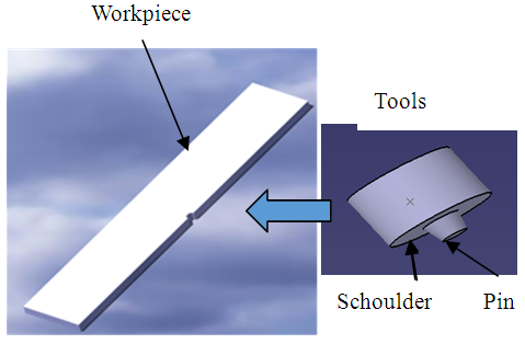 | Figure 1. Schematic representation of Workpiece and tool |
2. Material and Geometry
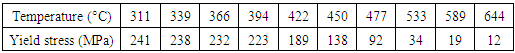
- In this section, the strategy adopted for the numerical simulation of the FSW process is presented. First, it is important to choose the materials of work-piece. Secondly, it is interesting to choose the different geometries of tool. Typical values of the properties of this material are given in table 1 and table 2.
|
|

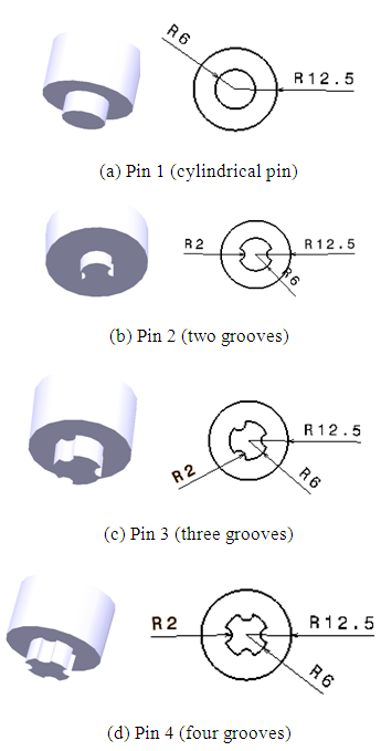 | Figure 2. Different Tool Geometries |
3. Boundary Conditions
- The model dimensions are (350 x 200x 6)m m in positive x, y and z directions respectively. Aluminum alloy (AA6061-T6) is taken as the work piece due to its wide applications in the aerospace field because of its good formability, weldability, machinability, corrosion resistance and good strength compared to other aluminum alloys. Equation (1) describes the steady-state heat transfer in the plate where a convective term (right-hand side) is included to account for the effect of material movement.
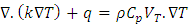 | (1) |
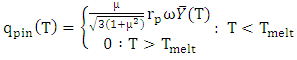 | (2) |
 is the pin heat flux and
  is the friction coefficient between the pin and the workpiece,
  denotes the pin radius,
  refers to the pin’s angular velocity (rad/ s), and
  is the average shear yield stress of the material as a function of temperature.
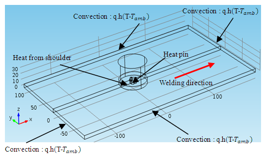 | Figure 3. Boundary conditions in the presented heat transfer model |
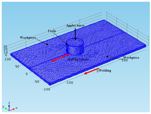 | Figure 4. Meshed workpiece as well as tool utilized during simulation of friction stir welding |
4. Results and Discussions
- FSW welding process was modeled by Comsol Multiphysics to do a thermal analysis. Temperature distribution in tools resulting from the simulation of FSW is schematically shown in Figure 5. The welding conditions in this section are fn=15 kN and ω=800 rpm. According to these results, it is clear. That the maximum temperature is about T=916 K in the cylindrical tool. This temperature does not exceed melting temperature of the alloy, equal to T=922 K.
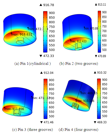 | Figure 5. Comparison between the peak temperatures (3D view) |
4.1. Effect of Axial Force
- In this section, all results presenting the thermal distribution of the numerical model are presented and interpreted as well as those presented in the following sections were obtained from the following configuration welding: - Different vertical forces equals to 9 kN, 10 kN, 11 kN, 12 kN, 13 kN, 14 kN, 15 kN and 16 kN, - welding speed (9.5 mm/s) speed of 800 rpm,- geometry Tool 4 (four grooves).Figure 6 shows the temperature map in the plates during welding. According to these results, the temperature gradient is much higher than before the tool. The cooling plates are controlled by interaction with the external environment. Figure 7 shows the evolution of the temperature in the middle line of the assembled samples. This fact increases the penetration force leads to an increase of the maximum temperature. Figure 8 shows the maximum temperatures as function of axial force for a constant welding speed of 9.5 mm/s. Notice how the maximum temperatures stabilize for higher rotational speeds – being limited by the melting temperature of 922 K.
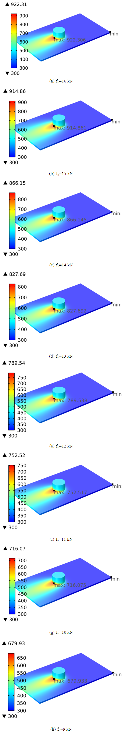 | Figure 6. Temperature distributions obtained for different axial forces |
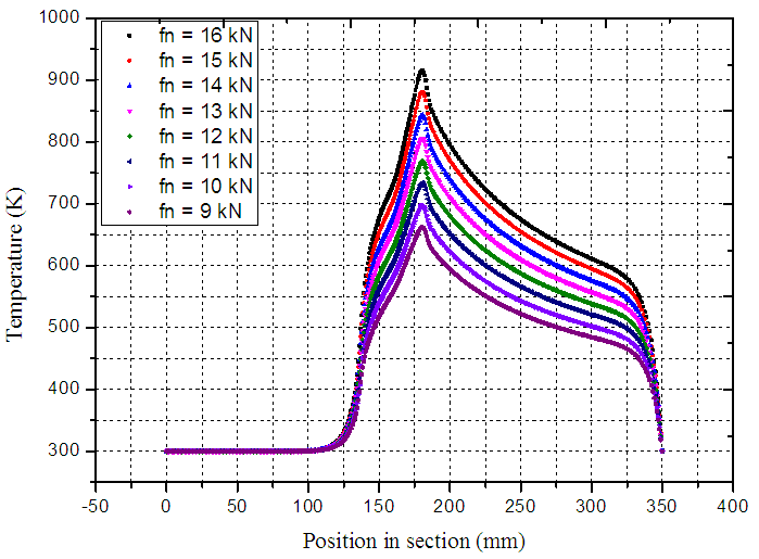 | Figure 7. Line-graph of the temperature along the midsection for different axial force |
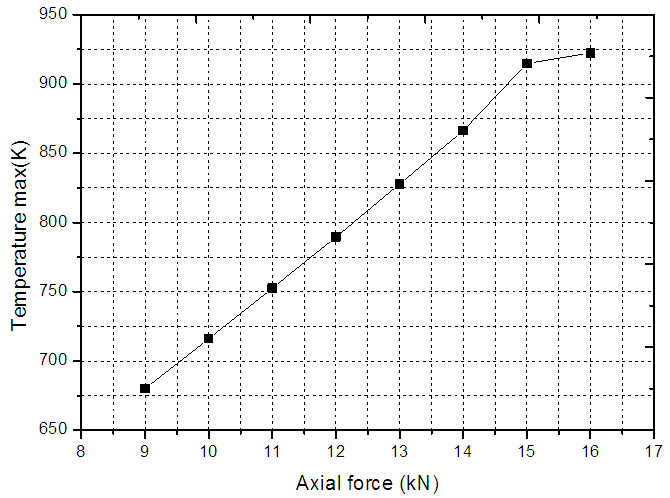 | Figure 8. Variation of the maximum welding temperature at the stir-zone close to the pin |
4.2. Effect of the of Rotation Speed
- To study the influence of rotation speed, we set the values of the forward speed of welding and the effort applied in this case, Figure 9 shows the variation of the maximum temperature in function of the rotation speed. According to these results, it is clear that the maximal temperature increases with the increase of the rotational speed as a linear function. It is clear that the maximum value Tmax is obtained with a rotation of 800 rpm. These simulations were performed with the geometry 1, and confirm the results developed by Chiumenti [9].
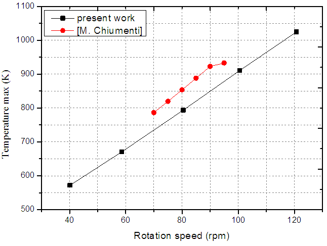 | Figure 9. Variation of the maximum temperature in function of rotational speed |
4.3. Effect of Feed Rate
- In this section, the welding conditions are
 and
and  Figure 10 shows the variation of the maximum temperature simulated as a function of the welding speed. According to these results, it has been noted that the maximum temperature decreases with the weldin speed as a linear function. The maximum value of the temperature is equal to
  for a welding speed equal to V = 9.3 mm/s.
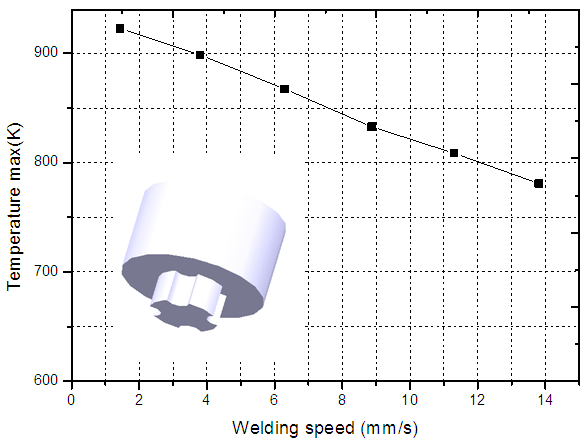 | Figure 10. Effect of welding speed |
5. Conclusions
- In this paper, we have used the Comsol multyphysics code to investigate the thermal analysis in friction stir welds.This study focused of the temperature variation reached during the movement of the welding material during the welding. The effect of the geometry of pin, as well as the speed of rotation of the tool, the penetration effort and the forward speed has studied. The comparison of the numerical results with the anterior results founded from the literature confirms the validity of the numerical method. The results obtained in this paper are as follows:- Tool probe geometry is very much responsible for deciding the weld quality.- The maximum value of the temperature obtained near the weld increases as the tool holding time and rotational speed are increased.