Fareh Hamrit1, Brahim Necib2, Zied Driss3
1Mechanical Engineering Department, Faculty of Technology Sciences, University of Constantine 1, Algeria
2Laboratory of Mechanics, University of Constantine 1, Campus Chab Ersas 2500 Constantine, Algeria
3Laboratory of Electro-Mechanic Systems, National School of Engineers of Sfax, University of Sfax, Tunisia
Correspondence to: Zied Driss, Laboratory of Electro-Mechanic Systems, National School of Engineers of Sfax, University of Sfax, Tunisia.
| Email: |  |
Copyright © 2015 Scientific & Academic Publishing. All Rights Reserved.
Abstract
The finite element method is used to solve problems by dividing the deformable body in a complicated assembling sub domain form or by constructing single elements and the approximate solutions in the form of a combination of shape functions and compact support. Our paper is mainly based on the application of this method to examine the mechanical structures using beam finite element method. The excitation forces are based on periodic, random or impulsive ones. In our case, we present a numerical solution to describe the dynamic behavior of discrete structures which have applications of big importance in many sectors of the industry, such as the space or aerodynamic structures, mechanical constructions, robotics and civil engineering. Nowadays, this method is a powerful tool, available for reasonable costs with a reduced time of execution used for the analysis of these structures. In this work, we have developed PASCHAL language program, to calculate the displacements, reactions in nodes, the axial strengths in elements and the clean fashions of the structure. Examples of verification of our language have been made, under different loads and boundary conditions. Good results have been obtained compared to those using SAP 2000 and Robot 2009 software programs.
Keywords:
Finite element, Element beam, Matrix of rigidity, Thrust loads, Nodal displacement, Vibration modes
Cite this paper: Fareh Hamrit, Brahim Necib, Zied Driss, Analysis of Mechanical Structures Using Beam Finite Element Method, International Journal of Mechanics and Applications, Vol. 5 No. 1, 2015, pp. 23-30. doi: 10.5923/j.mechanics.20150501.04.
1. Introduction
The discrete structures are composed of bar, beam elements riveted or welded to each other at points called "nodes", and subjected to external forces or moments. Under the effect of these forces, the structure may be deformed and the internal stresses in each element may occur. These structures are characterized by a finite number of unknown displacements and the forces at the nodes parameters. This method is used also to analyze continuum three dimensional bodies or cylindrical bodies using plate, triangular or shell elements. In fact, this method is based on the discretization of the structure or continuous body into infinitesimal elements limited by nodes and then by assembling them in order to obtain the overall and the entire structure [1]. Thus, the shape of the structure or the body is obtained in respecting its conditions with the initial limits and applied efforts. In general, the behavior of all the assembled basic members describes all of the behavior of the whole structure or body. The present work consists on the use of this method for static and dynamic analysis of structures under the influence of outside excitation with different boundary conditions. The stiffness and mass matrix of each element is computed, and then assembled to find the overall stiffness and mass matrix of the structure. In fact, the finite element method is known as a very powerful technique used to analyze discrete or continuum structures, in the field of engineering. It is now used in many sectors of the industry, mechanical, civil, aerospace and robotics. This work is devoted to the use of this method for analysis of structures in porches (beam element) due to excitement outside with different boundary conditions. Understanding this method gives necessity in the development of certain scientific knowledge as the theory of elasticity, mechanical environment continues, the strength of materials, structural dynamics, and applied mathematics. If the structure has a complex system of behavior and continues defined by the infinite number of parameters, it becomes very difficult to analyze or find the analytical solution [2]. However, the finite element method grows the ability to find the most perfect solution while replacing the continuous system by a discrete system, characterized by a finite number of parameters [3]. Sauer and Mergel [4] developed a nonlinear beam formulation that is suitable to describe adhesion and debonding of thin films. The formulation is based on a shear flexible, geometrically exact beam theory that allows for large beam deformations. The theory incorporates several aspects that have not been considered in previous theories before. Two different adhesion mechanisms are considered here: adhesion by body forces and adhesion by surface tractions. The new formulation is used to study the peeling behavior of a gecko spatula. It is shown that the beam model is capable of capturing the main features of spatula peeling accurately, while being much more efficient than 3D solid models. Alotta et al. [5] presented a finite element method for a nonlocal Timoshenko beam model recently. The model relies on the key idea that nonlocal effects consist of long-range volume forces and moments exchanged by non-adjacent beam segments, which contribute to the equilibrium of a beam segment along with the classical local stress resultants. The long-range volume forces/moments are linearly depending on the product of the volumes of the interacting beam segments, and their relative motion measured in terms of the pure beam deformation modes, through appropriate attenuation functions governing the spatial decay of nonlocal effects. Ghoneim [6] developed numerical modeling of isothermal solutal melting and solidification in binary systems using a new mesh free interface-finite element method where the implicitly represented liquid-solid interface is allowed to arbitrarily intersect the finite elements. A mesh free radial basis functions (RBFs) method is used for solving a distance-regularized level set (DRLS) equation such that re- initialization is completely eliminated and fast marching algorithms for interfacial velocity extension are not necessary resulting in a more efficient solution with excellent volume conservation. Kim et al. [7] presented an effective p-version two-node mixed finite element for predicting the free vibration frequencies and mode shapes of isotropic shells of revolution. The present element considering shear strains is based on Reissner-Mindl in shear deformation shell theory and Hellinger-Reissner variational principle. To improve the accuracy and resolve the numerical difficulties due to the spurious constraints, field-consistent stress parameters are employed corresponding to displacement shape functions with high-order hierarchical shape functions. The elimination of stress parameters and the reduction of the node less degrees by the Guyan reduction yield the standard stiffness and mass matrix. Brighenti and Bottoli [8] developed an exact one-dimensional beam finite element with composite cross-section. The element formulation is developed starting from the analytical solution provided in the recent literature, without the need to introduce any shape function for the interpolation of the element displacements and rotation fields. Moreover the formulated finite element allows to solve cases involving beams characterized by different axial displacements of the two cross-section parts, i.e. it offers the possibility of taking into account the lack of continuity of the axial displacement of one or both elements constituting the cross-section. Donà et al. [9] presented a computationally efficient beam finite element for the static and dynamic analysis of frame structures with any number and location of concentrated damages, whose macroscopic effects are simulated with a set of longitudinal, rotational and transversal elastic springs at the position of each singularity. The proposed mathematical model exploits positive Dirac’s deltas in the corresponding flexibility functions of the beam elements, and allows also considering shear deformations and rotatory inertia. Teng et al. [10] presented the finite element approach that is capable of accurate predictions of such debonding failures, with particular attention to plate-end debonding. In the proposed FE approach, a mixed-mode cohesive law is employed to depict interfacial behaviour under a combination of normal stresses and shear stresses; the interfacial behaviour under pure mode-I loading or pure mode-II loading is represented by bi-linear traction-separation models. Damage initiation is defined using a quadratic strength criterion, and damage evolution is defined using a linear fracture energy-based criterion. Detailed finite element models of steel beams tested by previous researchers are presented, and their predictions are shown to be in close agreement with the test results. Gao et al. [11] analyzed nonlinear contact problems of a large deformed beam on an elastic foundation. The beam model is governed by a nonlinear fourth-order differential equation. Based on a decomposition method, the nonlinear variational inequality problem is able to be reformed as a min–max problem of a saddle Lagrangian. Therefore, by using mixed finite element method with independent discretization-interpolations for foundation and beam elements, the nonlinear contact problem in continuous space is eventually converted as a nonlinear mixed complementarity problem, which can be solved by combination of interior-point and Newton methods. Applications are illustrated by different boundary conditions. Results show that the nonlinear Gao beam is more stiffer than the Euler-Bernoulli beam.In this context, a program of computation based on PASCHAL language has been developed. The displacements, forces and reactions at the nodes as well as the axial strengths in each element and the clean fashions of the all structures have been analyzed under different applied loads and boundary conditions. The obtained results are compared to those found using existing programs such as "SAP 2000" and "Robot 2009". A good comparison has been observed.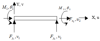 | Figure 1. Element beam in local coordinates |
2. Problem and Methodology
The finite element method is based on the geometric shape of the structure (element bar, beam, plate and hull). The discretization of these structures provides an elementary matrix dislodgment depending on the strain energy, to provide an overall stiffness matrix. After the implementation of boundary conditions and loads, we calculate the unknown in all nodes displacements and the stresses (axial strength) in all elements. Forces are applied to the structure to determine the mass matrix. The dynamic analysis of bending selects the best condition to limit the structure [12].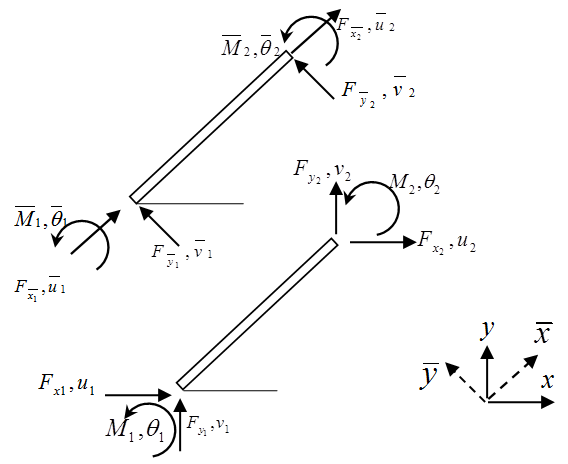 | Figure 2. Transformation of the local coordinates in global coordinates |
3. Mathematical Formulation
3.1. Function of Displacement
For an element of beam, the equation of balance is given by the following formula [13]:  | (1) |
The behavior of the beam is described by a polynomial function of the 3 degrees. It is the function of displacement and the solution of this equation [14]: 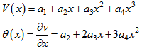 | (2) |
The coefficients of displacement and the displacement vector coefficient can be obtained by using the boundary conditions for the nodes. The displacement nodes equations can be written in matrix form as follow [15]: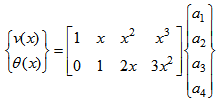 | (3) |
Using the equations (2) and (3), we can write the matrix form: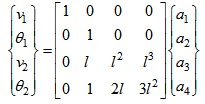 | (4) |
Or: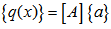 | (5) |
The inverse shape of this equation gives expressions of constants  . After substitution of the coefficients in the equation (3) and rearrangement, we can present the final shape of the displacement function:
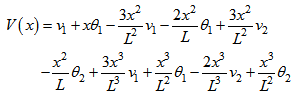 | (6) |
Then: | (7) |
Also, functions of shape can be written as follows: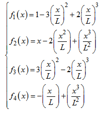 | (8) |
3.2. Vibration of Bending of an Element Beam
The kinetic energy of an element beam in vibration of bending is defined as follows [16]: | (9) |
The expression of the potential energy of an element beam is written as follow: 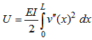 | (10) |
Where  indicates the derivative assists by report of
 . By replacing the function of x displacement (6) in the expressions (7) and (8), and after drifting by the Lagrange method, we get:
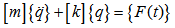 | (11) |
3.3. Matrix of Rigidity and Mass
The equation of movement can be gotten by the use of the Lagrange equation, written as follows: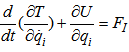 | (12) |
Where: | (13) |
While replacing equation (13) in the equation (12) and while supposing the absence of the potential energy we get:  | (14) |
This fact translates the first law of Newton. By substituting the equation of displacement (6) for an element beam in the equation of the potential energy (10) and in the equation of the kinetic energy (9), and while calculating strengths from the equation (12), we get: 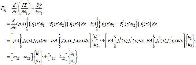 | (15) |
In the same way, we can calculate: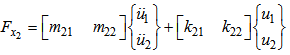 | (16) |
Or under general shape: | (17) |
 | (18) |
The explicit equations of movement resulting from the shape function are [17]: | (19) |
3.4. Free Vibration
The equation of movement for a vibration free of a beam is: 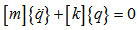 | (20) |
The displacement is sinusoidal of the shape: | (21) |
By substituting the equation (21) in the equation (20), we can write: 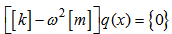 | (22) |
To determine the clean fashions of the structure to solve the system of equation [18]: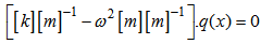 | (23) |
Then:  | (24) |
Where λi are the absolute values of the equation, to which correspond absolute vectors.
4. Structure Characteristics
The structure is an element beam, metallic and supported merely to these extremities. These geometric features have a square section S=0.0244 m2, a length lattice L=2.85 m and a height H=4.5 m. The mechanical properties of the material are given by the Young’s modulus E=200 GPa and the density ρ=7849 kg.m-3. The considered force is equal to F=10000 N.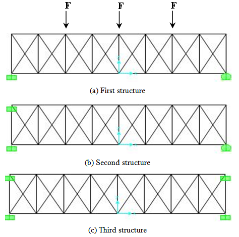 | Figure 3. Structures of beam |
5. Results and Discussion
Using our code, we have performed the calculation of normal modes directly from input data of the mechanical problem as the mass matrix of the whole structure in the frequencies making clean. This code is elaborate for advanced computing vibration modes studies [19]. Here, we consider a model without damping [20], preload without structure, and with a number of degrees of reasonable freedom. The most ergonomic solution is to use our computer code.
5.1. Vibration Modes
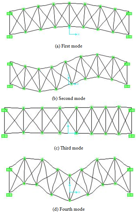
In the vibration analysis of three structures, we have determined the first four vibration modes with different boundary conditions and with the same load of three different structures as shown in figures 4, 5 and 6. In this study, we calculate the natural modes of vibration of a mechanical structure without external excitation. 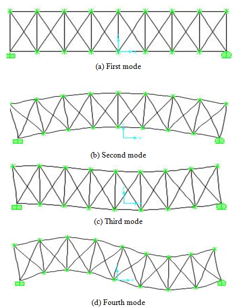 | Figure 4. Vibration modes of the first structure |
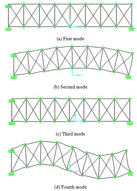 | Figure 5. Vibration modes of the second structure |
 | Figure 6. Vibration modes of the third structure |
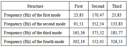
Table 1. Frequency for the three structures
 |
| |
|
5.2. Displacements
Figures 7, 8 and 9 present the variation of the displacements under the axis X(u), the axis Y(v) and the rotation angle θrespectively. According to these results, it has been noted that the maximal displacements under the axis X(u) and Y(v) are obtained in the second and the seventeen nodes. However, the maximal displacements under the rotation angle θis obtained in the third node. The good agreements between the numerical results developed using our developed program and the SAP 2000 program confirm our numerical method.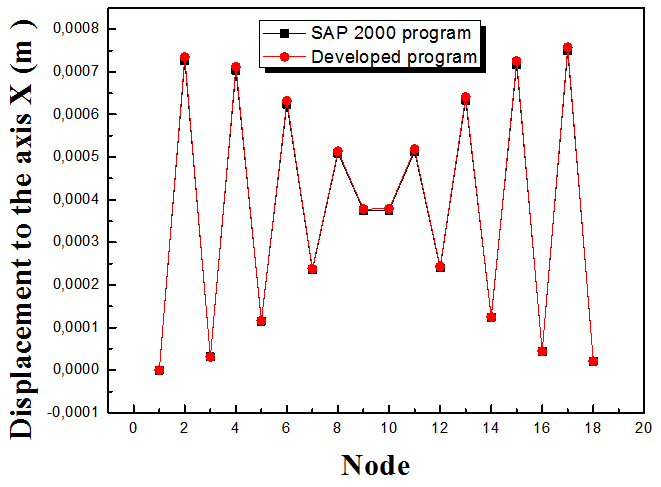 | Figure 7. Comparison of the displacements under the axis X(u) |
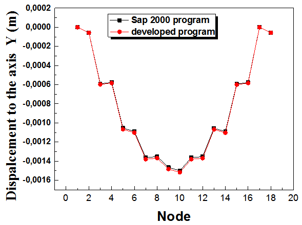 | Figure 8. Comparison of the displacements under the axis Y(v) |
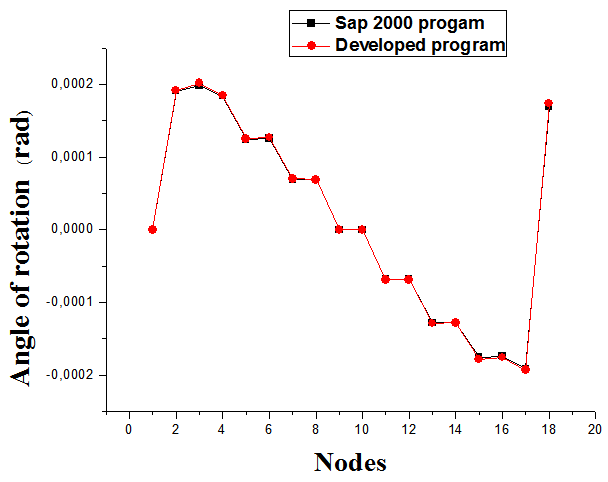 | Figure 9. Comparison of the displacements of the rotation angle |
5.3. Reactions
Figure 10 presents the variation of the reaction over the nodes. According to these results, it has been noted that the maximal value of the reaction is obtained in the first node. However, the minimal value of the reaction is obtained in the eighteen node. The good agreements between the numerical results developed using our developed program and the SAP 2000 program confirm our numerical method.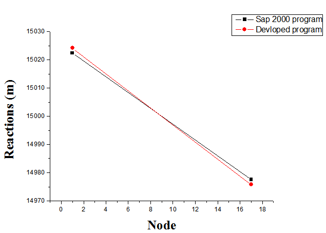 | Figure 10. Variation of the reaction |
5.4. Axial Strength
Figure 11 presents the variation of the axial strengths over the elements. According to these results, it has been noted that the maximal value of the axial strength is obtained in the twenties-two element. However, the minimal value of the axial strength is obtained in the twenties element. The good agreements between the numerical results developed using our developed program and the SAP 2000 program confirm our numerical method.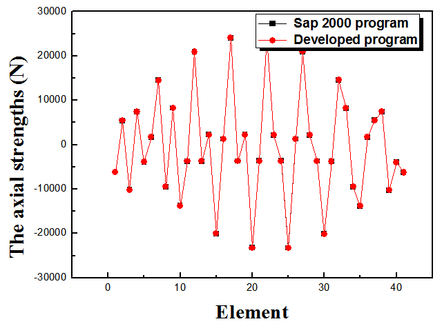 | Figure 11. Variation of the axial strength |
6. Conclusions
Analysis of mechanical structures using the finite element method has been done to analyze different discrete structures. This method allows us to obtain the specific modes of discrete structures under different boundary conditions. The results have presented the effect of the change of applied loads due to the different boundary conditions and the weight of the structure. It has been seen that the first structure (simply-simply supported) has the minimum free vibration mode which corresponds to the minimal axial strength in the elements of the structure and the minimal displacements and rotations at each nodes. Also, it has been noted that the results obtained using our developed program present a good agreement with SAP2000 program that confirms our developed numerical method and our numerical code of calculation. These results will allow us to choose the appropriate structure with minimal element axial stresses and node displacements.
References
| [1] | A. Fortin, Les éléments finis de la théorie à la pratique, Ecole polytechnique de Montréal, 2011. |
| [2] | A. El Ghazi, S. El Hajji, Guide d’utilisation du logiciel MATLAB, département mathématiques et informatique, Université Mohammed V, Maroc, 2004. |
| [3] | Pierre Spiteri, Présentation générale de la méthode des éléments finis, Ecole nationale supérieur de Toulouse, article [AF505]. |
| [4] | R.A. Sauer, J.C. Mergel, 2014, A geometrically exact finite beam element formulation for thin film adhesion and debonding, Finite Elements in Analysis and Design 86, 120-135. |
| [5] | G. Alotta, G. Failla, M. Zingales, 2014, Finite element method for a nonlocal Timoshenko beam model, Finite Elements in Analysis and Design, 89, 77-92. |
| [6] | A. Ghoneim, 2015, A mesh free interface-finite element method for modeling isothermal solutal melting and solidification in binary systems, Finite Elements in Analysis and Design, 95, 20-41. |
| [7] | J.G. Kim, J.K. Lee, H.J. Yoon, 2015, Free vibration analysis for shells of revolution based on p-version mixed finite element formulation, Finite Elements in Analysis and Design, 95,12-19. |
| [8] | R. Brighenti, S. Bottoli, 2014, A novel finite element formulation for beams with composite cross-section, International Journal of Mechanical Sciences, 89, 112-122. |
| [9] | M. Donà, A. Palmeri, M. Lombardo, A. Cicirello, 2015, An efficient two-node finite element formulation of multi-damaged beams including shear deformation and rotatory inertia, Computers and Structures, 147, 96-106. |
| [10] | J.G. Teng, D. Fernando, T. Yu, 2015, Finite element modelling of debonding failures in steel beams flexurally strengthened with CFRP laminates, Engineering Structures 86, 213-224. |
| [11] | D.Y. Gao, J. Machalová, H. Netuk, 2015, Mixed finite element solutions to contact problems of nonlinear Gao beam on elastic foundation, Nonlinear Analysis: Real World Applications, 22, 537-550. |
| [12] | M. Lalanne, P. Berthier, J. Der Hagobian, Mécanique des vibrations linéaires, MASSON Edition, 1995. |
| [13] | T.Y. Yang, Finite element structural analysis, Prentice-Hall, 1986. |
| [14] | B. Necib, Théorie générale de la mécanique des milieux continus, Université de Constantine, 2010. |
| [15] | B. Necib, Les méthodes des éléments finis (MEF), Université de Constantine, 2011. |
| [16] | P. Trompette, Mécanique des structures par la méthode des éléments finis (Statique et dynamique), 1992. |
| [17] | M. Abdi, K. Mohamed, Numerical Simulation and Active Vibration Control of Piezoelectric Smart Structure. International Review of Mechanical Engineering, 3, 175-181, 2009. |
| [18] | O.C. Zienkiewiez, The finite element method in engineering analysis, Paris, 1991. |
| [19] | A. Lebeid, B.Necib, 2011, Analysis and numerical modelling of ceramic piezoelectric beam, International Review of Mechanical Engineering, 3, 454-456. |
| [20] | N. Brie, Mise en œuvre d'un calcul de modes propres d'une structure, EDF R&D, 2014. |
 Abstract
 Reference
 Full-Text PDF
 Full-text HTML