Jayann Ismar Lira Almeida, Marcelo Cavalcanti Rodrigues, Koje Daniel Vasconcelos Mishina
Department of Mechanical Engineering, Federal University of Paraiba, João Pessoa, Brazil
Correspondence to: Jayann Ismar Lira Almeida, Department of Mechanical Engineering, Federal University of Paraiba, João Pessoa, Brazil.
| Email: |  |
Copyright © 2014 Scientific & Academic Publishing. All Rights Reserved.
Abstract
This paper presents a proposed modeling of a pressure vessel under internal and external corrosion using the fitness for service (API 579). Fitness for service (FFS) assessment is a quantitative engineering evaluation of operational components. In the context of pressure vessels and piping systems, FFS assessment is performed periodically to ensure the operational safety and structural integrity. Nondestructive testing by ultrasound was used to obtain loss of thickness wall measurements for pressure vessel damaged and develop the modeling. The objective is to analyze and evaluate the values of Maximum Allowable Working Pressure (MAWP) provided by the Fitness for Service assessment using numerical thermal transient analysis using Finite Element. Results of MAWP are compared when it takes into account several variables that Fitness for Service considers, like the Future Corrosion Allowance (FCA) due to evolution of corrosion, the thickness uniform loss (LOSS) of the internally corroded areas and the changes of temperature affecting the structural integrity of the equipment. The results show that for the external corrosion the values proposed for MAWP levels 1 and 2 by fitness for service still kept the pressure vessel operating at risk according to the analyzes obtained. Furthermore, the Remaining Strength Factor (RSF) is lower for internal corrosion, indicating that for these conditions, internal corrosion is most critical that the external. Finally, it is proposed a reduction of the temperature working in order to increase the RSF. This work shows that the union of the numerical analysis with the fitness for service can be used with efficiency and objectivity in similar situations like this.
Keywords:
Pressure Vessel, Fitness for Service, Structural Integrity, Finite Element, Corrosion
Cite this paper: Jayann Ismar Lira Almeida, Marcelo Cavalcanti Rodrigues, Koje Daniel Vasconcelos Mishina, Modeling and Level 3 Fitness-for-Service Assessment of a Cylindrical Pressure Vessel with General Metal Loss in Conjunction with the Numerical Thermal Transient Analysis, International Journal of Mechanics and Applications, Vol. 4 No. 3, 2014, pp. 80-93. doi: 10.5923/j.mechanics.20140403.02.
1. Introduction
Structural integrity is of considerable importance in order to avoid failures of mechanical components and structures in a number of industrial sectors. They are considered to be an important tool for ensuring the safety and economy of an operating plant. Fitness for Service (FFS) assessment is widely used as a tool to demonstrate the structural integrity of ageing pressure components containing damage. The ability to demonstrate the structural integrity of an in service component that sustained some damage or contains a flaw is termed as integrity assessment or fitness for service and is extensively dealt with by assessment procedures such as R6 [1]. Pressure vessels are devices used in process industries, oil refineries, petrochemical, food and pharmaceutical industries. Telles [2] says that this equipment must be designed and constructed to avoid of the damages causes that are: excessive elastic deformation, including elastic instability, high local stresses, and high temperature creep, brittle fracture at low temperature, fatigue and corrosion.A number of FFS assessment procedures are available in practice e.g., API 579 [3], R5 [4] and R6 procedures, and SINTAP [5] which has been superseded by FITNET [6]. An overview of the SINTAP procedure has been given by Ainsworth et al. [7]. These procedures are mostly semi-empirical and are based on extensive experimental data. The most widely used criteria for assessment of corroded pipes are called "effective area methods." The methods include ASME B31G [8], Modified B31G and PRC RSTRENG [9]. The standard procedures for fitness for service evaluations in the oil and gas sector for pressurized components are from API 579, whose assessment procedures are in turn based on the ASME B31G and the RSTRENG criteria. In practice, fitness for service evaluations are conducted periodically in order to determine the acceptability of in-service components and structures for continued service. Extended evaluations are often carried out in an effort to schedule routine inspection and estimate the remaining life of the component.For pressurized equipment in operating plants, fitness for service prescribes three levels of structural integrity evaluations. Levels 1 through 3 are progressively more sophisticated. Each assessment level provides a balance between the degree of conservatism, the amount of required input, the skill of the practitioner, and the complexity of the analysis. Level 1 assessment is the most conservative screening criteria that generally includes the use of charts and tables, which can be implemented by plant technicians with a minimum quantity of inspect ion and component information. Level 2 assessments involve detailed calculations intended for use by plant engineering personnel with the help of a recommended procedure. Level 3 assessments requires a full rational analysis by specialists where advanced computational techniques such as nonlinear finite element analysis are engaged.The corrosion is one form of commonly occurring damage in pressure components used in industrial and other applications. Internal corrosion is caused by corrosive products inside the pressure vessel. External corrosion can occur in components exposed to hostile surrounding environments. Structural integrity assessments for components containing corroded areas are necessary to verify the acceptance of continued service. For the purpose of evaluation, corrosion spots are usually termed as locally thinned areas (LTA). Failure here implies that a certain predefined limiting criterion is exceeded, and does not necessarily indicate physical collapse. Limit criteria for ductile materials typical for pressure components are commonly based on limiting stress, maximum strain or displacement. This implies that the component is rendered unserviceable long before a state of physical collapse is reached.In API 579, the concept of a RSF is utilized to define the acceptability for continued service of a component containing a flaw. In terms of a plastic collapse load, the RSF is defined as (1): | (1) |
Where PLU and PLD are the plastic collapse loads of the component before and after damage, respectively. If the calculated RSF is greater than the allowable RSF, the component can continue to be in service without any repair or remediation till the next scheduled major maintenance. The recommended value for the allowable RSF is 0.90 for equipment in process services.The RSF is generally used as a quantitative measure of the remaining strength of damaged components or structures. Significant effort has been directed over the last two decades to the study of structural integrity of ageing pressure vessels and piping systems.Sims et al. [10] have studied the effect of thinned areas in pressure vessels and storage tanks in an effort to assess the remaining strength of the damaged structure. An empirical equation has been developed by curve fitting the inelastic finite element analysis (FEA) results. They have compared the results with ASME B31G criteria, which is commonly used for determining the remaining strength of corroded pipelines. The results are in reasonably good agreement with ASME B31G, especially for shells having a relatively smaller diameter-to-thickness ratio.Seshadri [11] has studied the evaluation of thermal hot spots in cylindrical pressure vessels using variational principles in plasticity. A simplified formula for RSF is proposed for quantifying the remaining strength of the vessel. Shell decay lengths are used in order to identify the “reference volume”, which essentially represents the kinematically active portion of the component or structure that takes part in plastic action. Indermohan and Seshadri [12] have extended the application of the concept to corrosion damage in cylindrical pressure vessels. A number of example problems have been worked out to demonstrate the method.Ramkumar and Seshadri [13] have studied the problem of internal and external corrosion in cylindrical pressure vessels by using the concept of reference volume along with the mα-multiplier. The results are compared with ASME B31G (1984) procedure and have shown that the proposed method gives improved estimate of the remaining strength of the structure. Tantichattanont et al. [14] have studied the thermal hot spot and corrosion damage in spherical pressure vessels. They have derived the expressions for decay lengths in spherical pressure vessels. RSF based on mα -multiplier has also been proposed for FFS evaluation.
2. Fitness for Service Analysis to Cylindrical Pressure Vessels
In Fitness for Service assessment, the thickness data are required on the component where metal loss has occurred to evaluate general metal loss. Computation of the minimum wall thickness, MAWP and membrane stress for existing equipment typically requires judgment on the part of the user to determine factors and parameters which may significantly affect the final results (e.g. code revisions, determination of allowable stresses for in service components, weld joint efficiency in corroded regions).Thickness readings which are required to determine the metal loss on a component are usually made using straight beam ultrasonic thickness examination (UT). This method can provide high accuracy and can be used for point thickness readings and in obtaining thickness profiles (continuous line scans or area scans can also be used to obtain thickness profiles). The limitations of UT are associated with uneven surfaces and access. The equipment analyzed was a pressure vessel made of steel ASTM A516 Grade 70 with longitudinal welded joint with 2.76 MPa (400 psi) of work pressure, 2.03 m (80 in) inside diameter, 0.032 m (1.25 in) of nominal wall thickness and FCA (Future Corrosion Allowance) of the 0.00254 m (0.10 in). The FCA must be established for the intended operating period, this corrosion allowance may be established based upon previous thickness measurements, from corrosion rates on equipment in a similar service, or from information obtained from corrosion design curves. Metal loss on both the inside and outside of a component should be considered when determining a future corrosion allowance. The Figure (1) shows the equipment with grid of inspection by ultrasound tests in the region corroded.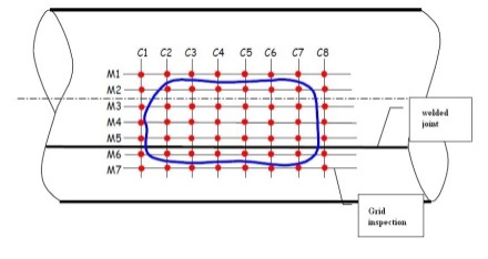 | Figure 1. The grid inspection in the region corroded |
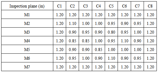
With automatic ultrasound testing aided the wall thicknesses profile of region with metal loss was collected. Each point is a longitudinal distance of 0.0635 m (2.5 in). The inspection grid was created around the region with corrosion (blue line). The Table 1 shows the values for the wall thickness by ultrasound tests in the longitudinal and circunferencial inspection planes.Table 1. Wall thickness for the longitudinal and circunferencial inspection planes
 |
| |
|
The mechanical properties of carbon steel begin to suffer a sharp drop in temperatures above 400°C, but in this case the temperature is about 177°C (350° F), so will not consider changes in steel properties due to temperature. Then, for low temperatures, the allowable stress is 137.70 MPa (19.90 ksi) A minimum of 15 thickness readings is recommended unless the level of NDT utilized can be used to confirm that the metal loss is general. In some cases, additional readings may be required based on the size of the component, the construction details utilized, and the nature of the environment resulting in the metal loss. The fitness for service assessment procedures are based on a thickness averaging approach which provides a suitable result when applied to uniform metal loss. If local areas of metal loss are found on the component, the thickness averaging approach may produce conservative results.The assessment procedures in this section can be used to evaluate all forms of general metal loss (uniform or local) which exceeds or is predicted to exceed the corrosion allowance before the next scheduled inspection. The general metal loss may occur on the inside or outside of the component. Assessment procedures based on thickness profiles and point thickness readings are provided.The fitness for service analysis can be made by considering external and internal corrosion, in other words, the reading points of inspection may be considered to assume both corrosion on the internal wall and external wall of the pressure vessel. The difference is the presence of parameter LOSS, metal loss in the shell, when corrosion takes place internally, and the presence of this factor puts the pressure vessel in an even greater risk.The procedures in API 579 are developed to overcome the shortcomings of the former inspection codes for pressure vessels and piping which are mainly based on empirical data and past experience (1992). In developing them, extensive validation based on both numerical analysis and physical testing has been applied to various damage modes such as metal loss and crack-like flaws. In that regard, further enhancements to Level 2 procedures in damaged areas such as hot spots are of significant interest. Thermal hot spots and corrosion areas are common damages that occur in in-service pressure vessels and piping systems. FFS assessments of these components need to be performed periodically in order to determine the suitability of a component for the prevailing operating conditions and for the assessment of remaining life.
2.1. Analysis of Fitness for Service in Applied Pressure Vessel Considering External Corrosion
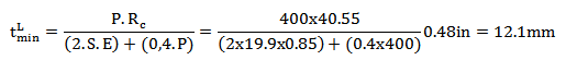
Here are the following steps to assess the fitness for service of the vessel to the region damaged by external corrosion. Calculate the minimum required thickness circumferential and longitudinal, respectively, shown in Eq. (2) and (3), and the greater of them will serve as a reference for future calculations: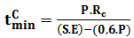 | (2) |
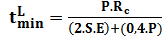 | (3) |
Where, S and E are respectively the allowable stress of the material and efficient welding (which for this case is unknown and is used 0.85), P is the original design pressure, 2.76 MPa (400 psi), and Rc has been defined as shown in Eq. (4): | (4) |
Substituting the values:
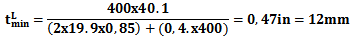
 Similarly, is found the minimum required thickness longitudinal:
 From these two values, the maximum between the two is used, in which case:
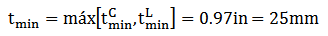
 It is now estimated the minimum thickness inspected by ultrasound and the remaining thickness ratio given by Eq (5):tmm = 20.32 mm (0.8 in) (See Table 3.2);
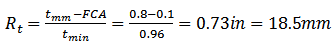 | (5) |
The API 579 shows that: 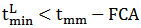 can discard the use of circumferential measures. In fact, by equation (6):
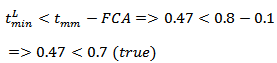 | (6) |
The next step is to determine the length of thickness average, as shown in equation (7):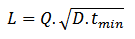 | (7) |
Where D is the inside diameter. The Q factor is found using the following equation (8):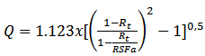 | (8) |
The API 579 says that when do not know the Remaining Strength Factor Allowable (RSFa), it is recommended to use 0.9; so: Q = 1.1. Finally, the value of L is 254 mm (10 in), for the value of the average thickness, can obtain an average minimum thickness, for this, it is found in columns C3, C4, C5, C6 and C7, the minimum thickness measured and an arithmetic average is compared to the average thickness length (L), and L = 254mm (10 in) for each value found in the column is repeated once more, and thus it has been 10 values to the average thickness as shown in Equation (9):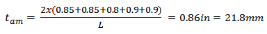 | (9) |
From this, the evaluation can be performed and can determine, if the component can continue to operate, according to Eqs. (10) and (11) below from level 1: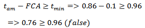 | (10) |
 | (11) |
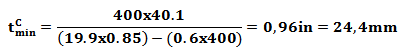
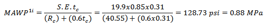
As one of the equations is false, the vessel can only operate safely with the following MAWP showed at Eq. (12):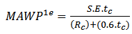 | (12) |
Where tc is calculated as shown in Eq. (13): | (13) |
So, the MAWP1e is:
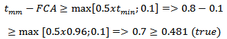
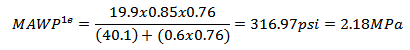 Thus with MAWP of 2.18 MPa (316.97 psi), which is smaller than the work pressure of 2.76 MPa (400 psi). As the level 1 was not satisfied, the level 2 has to be done.The difference between these levels is the presence of Remaining Strength Factor (RSFa), as already shown, that for unknown values can be considered 0.9. Thus, the pressure vessel can operate safely if the following equation is satisfied, see Eq. (14).
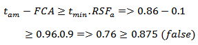 | (14) |
With this, the 2nd level also does not meet API 579 and the maximum allowable pressure is: given by Eq. (15):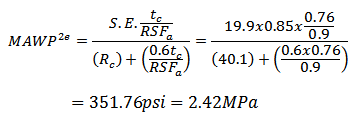 | (15) |
According to the second level, the maximum allowable pressure is 2.42 MPa (351.76 psi), which is also below the design pressure.
2.2. Analysis of Fitness for Service in Applied Pressure Vessel Considering Internal Corrosion
The procedure is very similar to analysis of external corrosion, the main difference to examine the corrosion vessel with external and internal corrosion is the presence of a uniform metal loss, called LOSS that exist in internal corrosion, so the tc and Rc is calculated as shown in the Eqs. (16) and (17):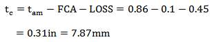 | (16) |
 | (17) |
The new circumferential and longitudinal thicknesses are, in this order:


 Similarly to external corrosion, it is used the maximum of these two values:
 Thus, the analysis of level 1 API 579 is done:
 Therefore, the level 1 does not satisfy, calculating the pressure that the pressure vessel can operate safely:
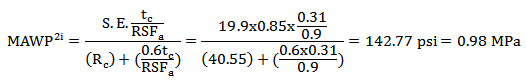
 Likewise, as the level 1 was not satisfied, need to assess the level 2, thus:
 Without satisfying the level 2, the pressure that can be safely operate according to Fitness for Service:
 It is evident that maximum allowable working pressures are much smaller in relation to the pressure derived from the external corrosion, therefore, LOSS is a factor that reduces abruptly the MAWP and thus, the internal corrosion is more severe than the external corrosion.
3. Modeling of the Cylindrical Pressure Vessel with the Corroded Region
Using the software NX 7.0 Siemens, is developed a pressure vessel model with metal loss region obtained by ultrasound testing. The Fig. (2) shows the modeling of corrosion through the plane M1 of Tab. (1). | Figure 2. First profile of the corroded area |
To obtain the second surface, which is shown through the plane of Table M2 (3.2), the modeling have the form shown in Fig. (3).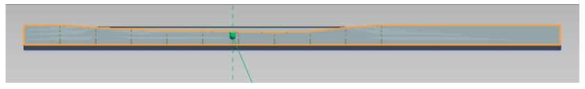 | Figure 3. Second profile of the corroded area |
See that the first profile is behind the second, continuing the modeling of the data showed at Tab. (1), we obtain the pressure vessel with the modeling of region corroded as shown in Fig (4).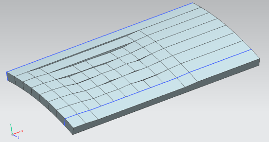 | Figure 4. Modeling the profiles of the zone with thickness loss |
Finally, it is necessary to finish the contour of the pressure vessel, note that the corroded region may be located externally or internally as shown in Fig. (5).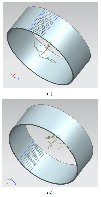 | Figure 5. (a) Modeling of cylindrical pressure vessel with metal loss in the external region. (b) Modeling of cylindrical pressure vessel with metal loss in the internal region |
4. Determination of Mawp Level 3 for the Pressure Vessel
After analyzing the levels 1 and 2 of API 579 previously done, the next steps are: analyze the pressure vessel corroded with the pressures found in level 1 and 2 of API 579 and check the von Mises stresses on the vessel wall and to find the MAWP of level 3 via numerical solution. For the case of pressure vessel without corrosion and the working pressure of 2.76 MPa (400 psi) was found by Finite Element Analyses (FEM) the von Mises stress of 110.4 MPa (16 ksi) as shown in Fig (6), and thus, a factor safety of 1.24.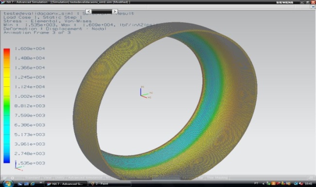 | Figure 6. Analysis of von Mises stress to the pressure vessel without corrosion |
For these analyzes to determine the MAWP level 3 was not considered the numerical thermal transient modeling, so, the working temperature of 177℃ (350°F) does not enter in this primary analyses, only the working pressure, so these situations, the pressure vessel is not in the transient state and there is no variation in von Mises stress. The grid size was set at 0.5 in, because it was the value that the results converged, much smaller than this did not significantly varied results obtained.
4.1. Determination of MAWP Level 3 for the Pressure Vessel with External Corrosion
In the first case, in possession with the design of the pressure vessel to the region of the thickness loss, the pressure applied found in level 1 of the API 579 of 2.18 MPa (316.97 psi) found a maximum von Mises stress of 148.24 MPa (21.5 ksi) which is greater than the allowable stress of 137.70 MPa (19.9 ksi), see Fig. (7-a). Similarly, it can be seen that the pressure level 2 of 2.42 MPa (351.76 psi) was also a Von Mises stress higher than the allowable stress of the material of 165.39 MPa (23.97 ksi), see Fig. (7-b). Thus, levels 1 and 2 proposed by API 579 for reduction of MAWP not put the vessel safely, as the analysis showed that for the pressures of the respective levels, the von Mises stresses exceeds the allowable stress of the material.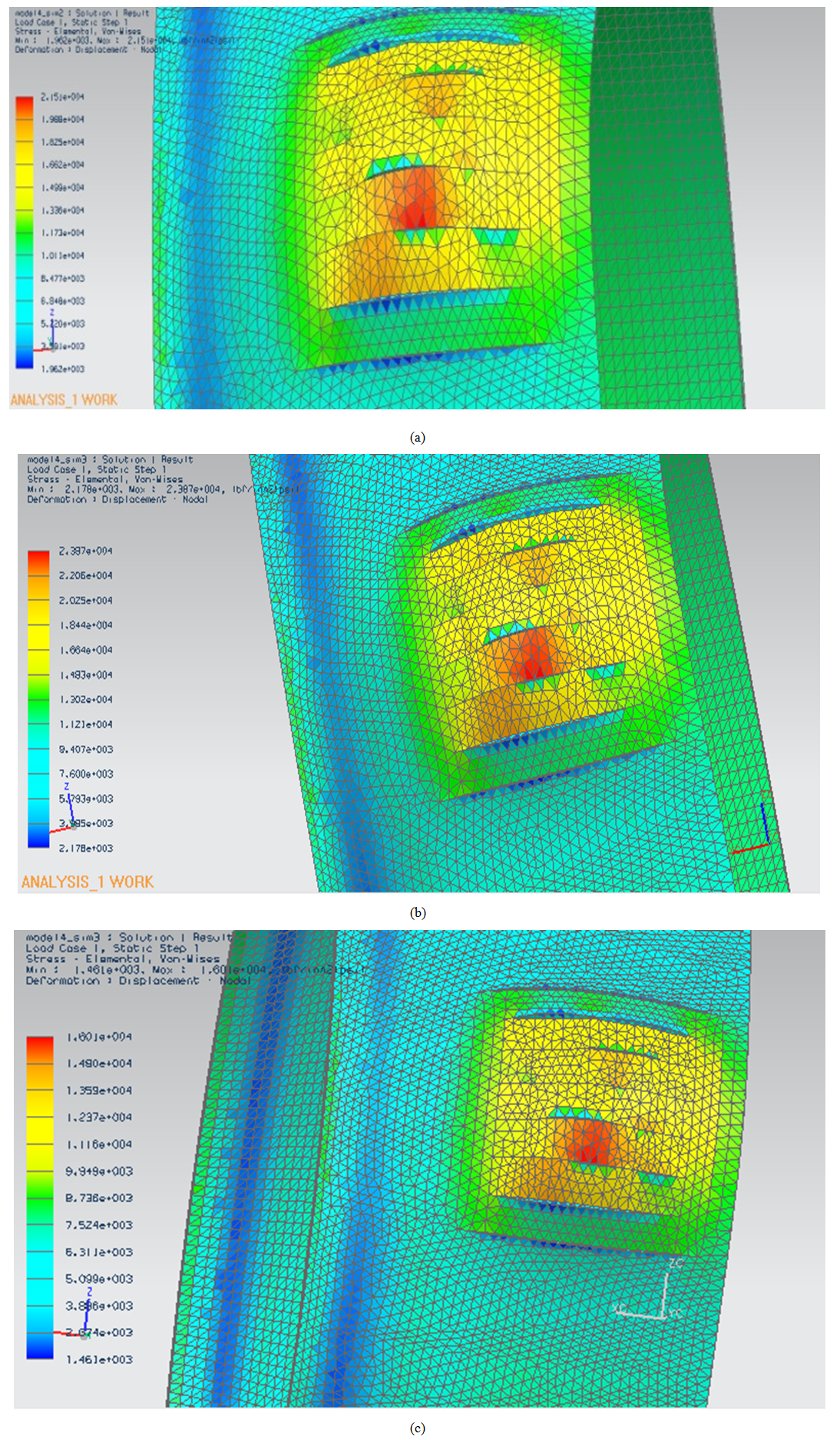 | Figure 7. Distribution of von Mises stress of a) 2.18 MPa, b) 2.42 MPa and c) 1.64 MPa |
The boundary condition is the fixed constraint of the side of the vessel and the pressure vessel was subject to constant internal pressure at initial condition. After several finite element analyzes in which these analyzes were examined various pressures until a pressure of 1.64 MPa (236 psi), corresponding to a von Mises stress of 110.32 MPa (16 ksi), as can be seen in Fig (7-c), it shows that with the external corrosion, this is the pressure which approaching the safety factor of 1.24 operating conditions without corrosion of the pipeline and the pressure from 2.76 MPa (400 psi).
4.2. Determination of MAWP Level 3 for the Pressure Vessel with Internal Corrosion
Similarly to what was done to external corrosion, the numerical analysis is done with pressures encountered by levels 1 and 2 of the API 579 with the zone of corrosion internally, for the pressure of 0.89 MPa (128.74 psi), the highest Von Mises stress was 114.94 MPa (16.67 ksi), see Fig. (8-a) and the permissible stress is 137.70 kpsi 19.9 MPa (19.9 ksi), level 1 is consistent and the vessel can operate at that pressure.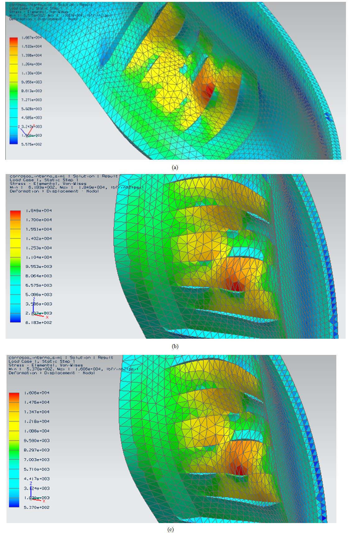 | Figure 8. Distribution of von Mises stress of a) 0.89 MPa, b) 0.98 MPa and c) 0.86 MPa |
For the pressure found in level 2 of 0.98 MPa (142.78 psi), the Von Mises stress found was 127.48 MPa (18.49 ksi), see Fig. (8-b). Thus, the second level also enables the vessel to operate safely. It is important to note that the point of maximum stress always occurs in the area of lesser thickness, as well as external corrosion.Finally, again after successive numerical analyzes is found the value of 0.86 MPa (125 psi), see Fig. (8-c), at which the Von Mises stress is near of the stress found in the initial conditions of 110.32 MPa (16 ksi) and a safety factor of 1.24.Then, it is noticed that in this situation the pressure reductions proposed by the Fitness for Service (levels 1 and 2) still put the pressure vessel operating at risk for external corrosion, so care should be taken before using these pressures. For internal corrosion pressures proposed by API 579 put the vessel to operate safely.
5. Numerical Thermal Transient Modeling of the Pressure Vessel
With the modeling of the pressure vessel with corrosion, the aim now is to make the numerical analysis to determine the temperatures to steady the walls of the duct, for this was made a transient thermal analysis in NX THERMAL, this analysis consisted of the following: The temperature imposed was the working fluid temperature of 177℃ (350oF), and the transient analysis was performeduntil the time of 900s, this time it is expected that the system enters the steady state, then it was decided that the analysis will be taken every 100s, including time 0s thus obtains 10 results.Notes are three heat transfers in this situation: Convective heat transfer between the fluid and the inner wall of the duct, which is at ambient temperature; Heat transfer by conduction between the walls of the duct; Heat transfer by convection between the outer wall of the duct and the environment.
5.1. Numerical Thermal Transient Modeling of the Pressure Vessel without Corrosion
Initially the vessel is at room temperature of 20℃ (68°F) and the working fluid at 177℃ (350°F), with the end of simulations, the temperature of the outer wall of 174.28℃ (345.7°F) was found, and the inner wall of 176,22℃ (349.2°F), as can be seen in Fig. (9):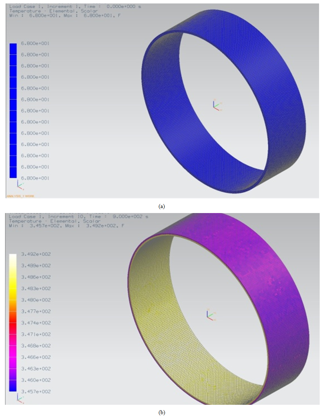 | Figure 9. Temperature distribution for the vessel without corrosion (a) initial time and (b) steady state |
5.2. Numerical Thermal Transient Modeling of the Pressure Vessel with External Corrosion
Can be observed that for the initial time, the vessel suffers no heat transfer, the vessel is at ambient temperature of 20℃ (68oF), in the last instant, the temperatures have stabilized, as can be seen in Fig. (10), with a value of temperature for the outer wall of 174.28°C (345.7°F) and the inner wall of 176.11°C (349.2°F).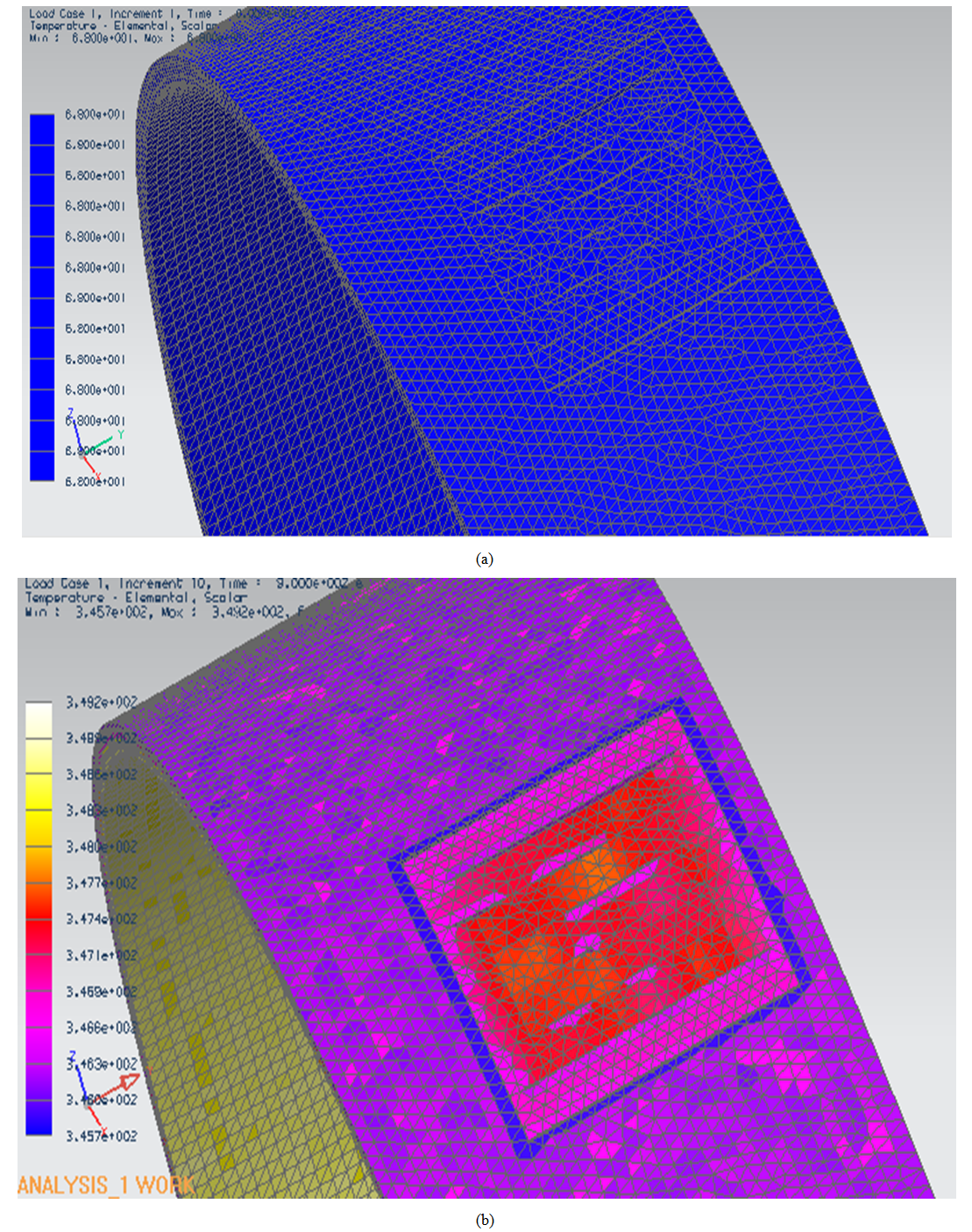 | Figure 10. Temperature distribution for the vessel with external corrosion (a) initial time and (b) steady state |
It can be seen that the profile is practically the same considering the vessel without damage, but a small peak temperature observed at time 100s, this peak originates from the hot spot, furthermore, the temperature at steady state are quite close, around 174℃ and 176℃.
5.3. Numerical Thermal Transient Modeling of the Pressure Vessel with Internal Corrosion
Now the same analysis was performed considering internal corrosion, to the initial instant, the same situation occurs on the external corrosion, at steady state the temperature on the outer wall at 174.28℃ (345.7°F) and the temperature of the inner wall at 176.44℃ (349.6°F), as can be seen in Fig. (11).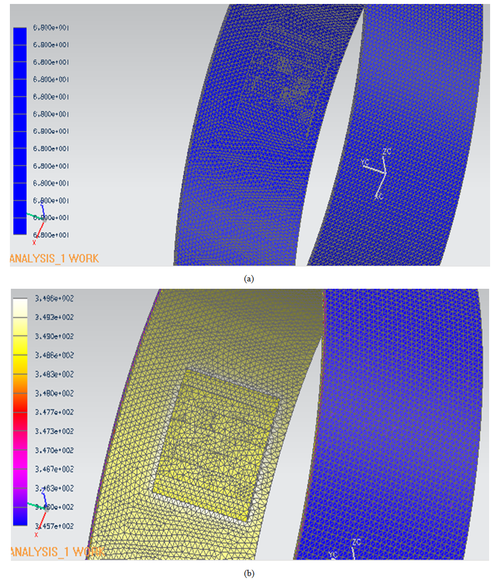 | Figure 11. Temperature distribution for the vessel with internal corrosion (a) initial time and (b) steady state |
6. Results
6.1. Distribution of von Mises Stress for the Pressure Vessel with Working Pressure of 400 psi
This part aimed at the numerical transient solution of the von Mises stress distribution in a pressure vessel considering the areas of corrosion on the inner and outer walls and the temperature of 177℃, so the peaks occurred in the region of greatest thickness loss (critical zone of corrosion), and with that, we analyze the behavior of the von Mises stress in the region, with both the external and internal corrosion, to analyze the stresses in the pressure vessel as the system enters the steady state. The initial conditions were: temperature of the pressure vessel 20℃ and working fluid temperature in which case water 177℃. The Fig. (12) shows the stress distribution to 2.76 MPa (400 psi) for the pressure vessel with external, internal damage and without damage.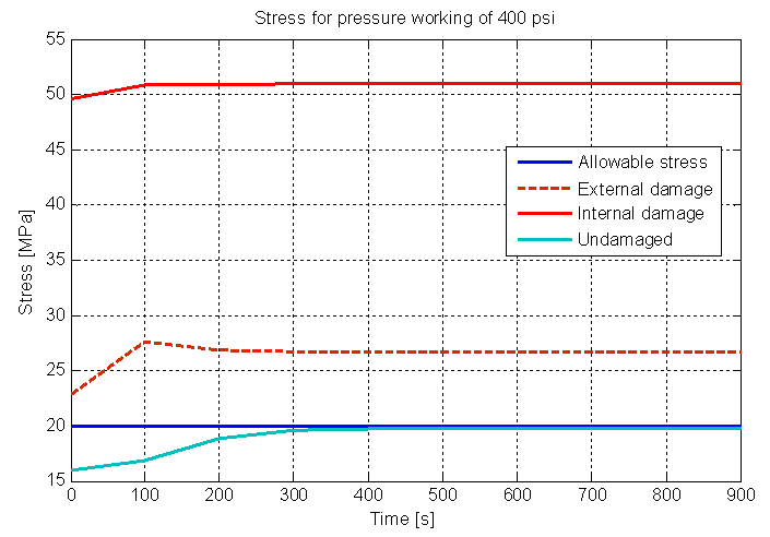 | Figure 12. Von Mises stress distribution to 2.76 MPa pressure working, without, external and internal damage |
It is noticed that the analyzes for the same operating pressure, the pressure vessel with internal corrosion is more critical than the external corrosion, since the values found in von Mises stress are higher because of the LOSS, that appears only in internal corrosion. Also note that the stresses encountered without considering the working temperature refers to time zero in the transient state, as can be seen in Fig. (9).
6.2. Distribution of Von Mises Stress for the Working Pressures Found by API 579 for the Pressure Vessel with External and Internal Corrosion
Only the pressure vessel with no corrosion is possible to perform operation safely. The results obtained from numerical analysis can summarize them in the following figures. In Figure (13-a) shows that the external corrosion showed stress peaks at time 100s for each level of API 579. It is seen that the pressure level 1 and level 2 we obtain a stress greater than the allowable stress of the material. Therefore, the pressure recommended by the level 1 and 2 of API 579 puts the pressure vessel at risk.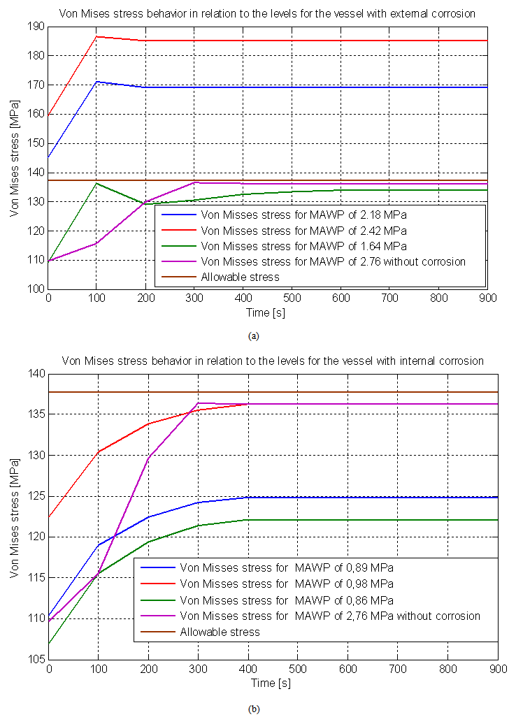 | Figure 13. (a) Structural and Transient analysis with external corrosion. (b) Structural and Transient analysis with internal corrosion |
The pressure level 3 of 1.64 MPa(236 psi), obtained via finite element analysis previously described, takes the vessel to have a stress distribution similar to the initial conditions of the project, and with that, in this pressure level 3, the vessel can operate safely, the pressures found at level 1 and 2 made the pressure vessel operating under risk, since their stresses was greater than the allowable stress of the material of the pressure vessel.In relation with the internal corrosion, both the pressure recommended by the API 579 generates maximum stresses lower than the allowable stress, as shown in Fig. (10-b). Note that the pressure found in the level 3 of 0.86 MPa (125 psi) obtained via finite element analysis, is very close to level 1. Moreover, both the level 1 and level 3 shows conservative results compared to level 2 and the pressures found are lower than for external corrosion, because the term LOSS entering the calculations of internal corrosion. Finally, the fitness for service analysis considering internal corrosion did not put the pressure vessel at risk.
6.3. Calculation of RSF
As already discussed, the RSF is a parameter used for quantitative assessment of damaged components and structures. The RSF is a dimensionless parameter and is based on the primary load carrying capacity of the structure. The RSF can be defined as the ratio of the collapse load of damaged component to the collapse load of the undamaged component.
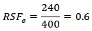
 The load to collapse plastic can be approximated by the initial working pressure of 2.76 MPa (400 psi), this approximation is valid since the tension acting in this situation is very close to the allowable stress, Through various simulations, it was found that the minimum pressure that brings risks to the pressure vessel with external corrosion was approximately 240 psi (1.66 MPa) and for internal corrosion was 145 psi (1 MPa), in other words, at pressures of 240 psi and 145 psi the vessel reaches its allowable stress of 19.9 kpsi (137.7 MPa) entering plastic collapse.the RSF based on external corrosion is:
 Therefore, if the pressure reduction is not possible in the pressure vessel, the other solution available is to apply a repair on equipment to minimize the effects of corrosion, or in the worst case, build a new pressure vessel. For the internal corrosion the RSF is:
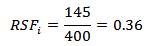 Even lower for internal corrosion. The vessel is operating with less than half of its cargo capacity due to this internal damage. Similarly to external corrosion, the damage to this vessel to achieve operating conditions in the initial design needs its RSF that is greater than 0.9. But as RSFi is very low, the best alternative is not repair, but the replacement of existing equipment.
6.4. Structural Analysis of Pressure Vessel with Reduction of Working Temperature with External Corrosion
The following analysis is performed of the structural integrity of the pressure vessel operating at a reduced temperature to observe what happens to the stress distribution. Temperatures analyzes proposals were: 126.85℃ (260.33°F), 66.85℃ (152.33°F) and ambient temperature 20℃ (68°F). The proposed reduction in their temperatures have tabled their properties. The MAWP used to observe the behavior of tension is the level 3 of API 579, it is the MAWP that brings security to the vessel. Fig (14) shows the stress distribution for the pressure of 236 psi (1.64 MPa) according to the working temperatures of 177℃ (350°F), 126.85℃ (260.33°F) 66.85℃ (152.33°F) and ambient temperature of 20℃ (68°F).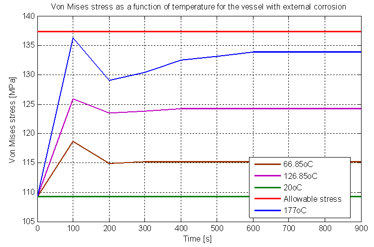 | Figure 14. Von Mises stress for MAWP level 3 relative temperatures |
Based on these results, it is possible to calculate a new RSF, so it is safe to say that for every change in the working temperature in the vessel has a new RSF due to increased MAWP. The Figure (15) shows the new values for MAWP due the temperatures.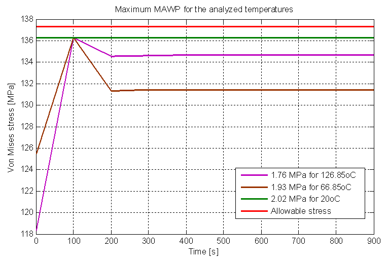 | Figure 15. Maximum MAWP for the analyzed temperatures for external corrosion |
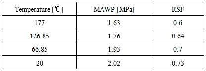
The Table (2) shows the RSF gain with temperature reduction:Table 2. RSF gain by reducing temperature to external corrosion
 |
| |
|
Note that the distribution of von Mises stress decreases when the temperature decreases, this is because also reduces the heat transfer that occurs between the working fluid and the walls of the pressure vessel. In fact, when equals the temperature of the pressure vessel with the temperature of the working fluid, no heat transfer and von Mises stress is constant from the beginning, not so with the transient state preceding the steady state.
6.5. Structural Analysis of Pressure Vessel with Reduction of Working Temperature with Internal Corrosion
A similar analysis is done for internal corrosion, but the MAWP used in this case is the level 2 of API 579, worth 0.98 MPa (142.78 psi) because it was the pressure that met the established criteria. The Figure (16) shows the new values for MAWP due the temperatures.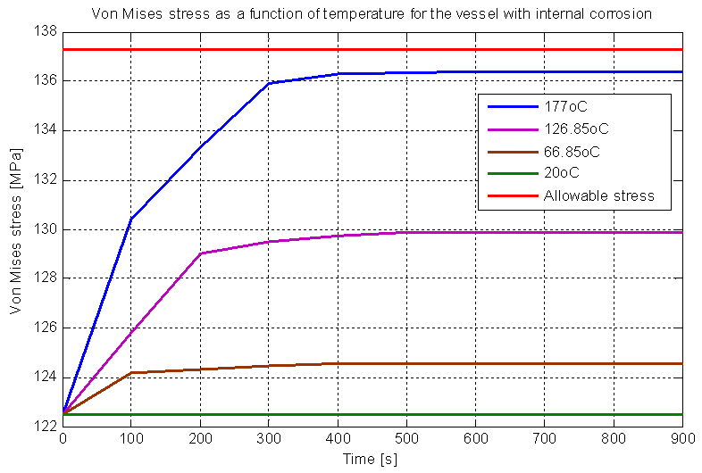 | Figure 16. Stress for MAWP level 2 relative temperatures |
Thus, the new MAWPs for each temperature are shown in Fig (17):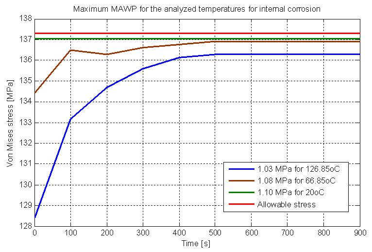 | Figure 17. Maximum MAWP for the analyzed temperatures for internal corrosion |
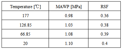
The Table (3) shows the RSF gain with temperature reduction:Table 3. RSF gain by reducing temperature to internal corrosion
 |
| |
|
Therefore, decreasing the temperature did not have a significant variation in RSF to the vessel with internal corrosion, the best solution in this case to achieve a considerable increase in the MAWP will require repairing the damage caused by the corrosion.
7. Conclusions
This paper analyzed the structural integrity of a cylindrical pressure vessel subject to corrosion degradation via numerical analysis to standard API 579. It was found that when the pressure vessel is subjected to a working temperature, the von Mises stress acting in the pressure vessel varies until the temperature stabilizes and the API 579 does not mention it. This increase in the von Mises stress is critical, because even for a pressure vessel without damage, the von Mises stress stabilizes near the allowable stress of the pressure vessel.The three levels of the API 579 were performed and it was found that for corrosion external, the pressure reductions by the level 1 and 2 of fitness for service put the pressure vessel operating at risk, and using the third level found by finite elements analysis as requested by Fitness-for-Service caused the vessel pressure operated safely. For internal corrosion, both pressure reductions proposed by the level 1 and 2, as the level 3 found by numerical solution put the pressure vessel to operate safely. It was clear that the reductions proposed by the pressures of API 579 does not takes into consideration the transient interval that happens in between the heat transfer of the working fluid with the pressure vessel, then a finite element analysis should be performed not only at level 3, but at all levels.The decrease in temperature can be a useful method in some situations (as seen in the case of external corrosion) to reduce the von Mises stress, and thereby obtain an increase in RSF. Therefore, a well-implemented numerical analysis can be the best option for the structural analysis of equipment in general (in this case, pressure vessel). This is because the objectivity and accuracy of the analysis with which the results can best predict the true service condition.
ACKNOWLEDGEMENTS
This work was supported by the CAPES, CNPQ, Federal University of Paraiba, Department of Mechanical Engineering, Precision Engineering Laboratory and Integrity and Inspection Laboratory.
References
| [1] | R6. Assessing the integrity of structures containing defects. British Energy, Gloucester, UK, 1995. |
| [2] | TELLES, P. C. DA SILVA, “Vasos de Pressão”, 2ª edição, Ed. LTC – LivrosTécnico e CientíficosEditora S.A, Rio de Janeiro, Brasil, 1996. |
| [3] | API Recommended Practice 579, Fitness for service, API Publishing Service (American Petroleum Institute), first edition, Washington D.C., Jan. 2000. |
| [4] | R5. Assessment procedure for the high temperature response of structures. British Energy 2003;3. |
| [5] | SINTAP. Structural integrity assessment procedure for European industry. Project BE95-1426, Final Procedure, British Steel Report, Rotherham; 1999. |
| [6] | FITNET. Fitness-for-service procedure. Final Technical Report. Geesthacht: GKSS Research Centre; 2006. |
| [7] | AINSWORTH RA, BANNISTER AC, ZERBST U. An overview of the European flaw assessment procedure SINTAP and its validation. Int J Pressure Vessels Piping 2000; 77:869 e 76. |
| [8] | ASME. Manual for determining the remaining strength of corroded pipelines. American National Standards Institute (ANSI)/ American Society of Mechanical Engineers (ASME) B31G. 1984. |
| [9] | KIEFNER JF, VIETH PH. A modified criterion for evaluating the remaining strength of corroded pipe (with RSTRENG). American Gas Assoc, Catalogue L51609, PR3-805. December 1989. |
| [10] | SIMS JR, HANTZ BF, KUEHN KE. A basis for the fitness for servisse evaluation of thin areas in pressure vessels and storage tanks. Pressure vessel fracture, fatigue and life management. ASME PVP 1992;233:51–8. |
| [11] | SESHADRI R. Integrity assessment of pressure components with local hot spots. J Pressure Vessel Technol 2005; 127:137e42. |
| [12] | INDERMOHAN H, SESHADRI R. Fitness-for-service methodology based on variational principals in plasticity. J Pressure Vessel Technol 2005; 127:92e7. |
| [13] | RAMKUMAR B, SESHADRI R. Fitness for service assessment of corroded pipelines based on variational principles in plasticity. J Pipeline Integrity 2005; 2:99e116. |
| [14] | TANTICHATTANONT P, ADLURI SMR, SESHADRI R. Structural integrity for corrosion in spherical pressure vessels. Int J Pressure Vessels Piping 2007; 84:749e61. |
 Abstract
 Reference
 Full-Text PDF
 Full-text HTML