Hamadache Hamid1, Taamallah Wahiba1, Zemouri Zahia2
1Department of Mechanical Engineering, Research Laboratory of Advanced Technologies in Mechanical Production (LRATPM), University Badji Mokhtar, BP. 12, Annaba, 23000, Algeria
2Department of Mechanical Engineering, Laboratory of Mechanics Materials and Industrial Maintenance, Mechanical Engineering (LR3MI), University Badji Mokhtar, BP. 12, Annaba, 23000, Algeria
Correspondence to: Zemouri Zahia, Department of Mechanical Engineering, Laboratory of Mechanics Materials and Industrial Maintenance, Mechanical Engineering (LR3MI), University Badji Mokhtar, BP. 12, Annaba, 23000, Algeria.
| Email: |  |
Copyright © 2014 Scientific & Academic Publishing. All Rights Reserved.
Abstract
This work focuses on the physical and geometrical aspect the surface layers of AISI / SAE 3115 having undergone treatment by ball burnishing hard steel or diamond tip. The results show that the optimal effects of burnishing are directly linked to the shape and the material of the active portion of the device as well as the ability to plastic deformation of the material surface to be treated. And roughness is improved over 68% and the rate of consolidation is increased by 24%. Also modelling rational curves traction provides a hardening coefficient up to 0.29 in the presence of burnishing.
Keywords:
Steel AISI / SAE 3115, Burnishing, Hardening, Roughness
Cite this paper: Hamadache Hamid, Taamallah Wahiba, Zemouri Zahia, Characterization Layers Hardened Burnished Steel AISI/SAE 3115, International Journal of Mechanics and Applications, Vol. 4 No. 1, 2014, pp. 13-19. doi: 10.5923/j.mechanics.20140401.03.
1. Introduction
Roller burnishing is a surface finishing technique in which hardened; highly polished steel rollers are brought into pressure contact with a softer piece part. As the pressure generated through the rollers exceeds the yield point of the piece-part material, the surface is plastically deformed by cold flowing of sub-surface material. The result is a mirror-like finish and a tough, work-hardened surface with load-carrying characteristics which make the burnished surface superior to finishes obtained by abrasive metal-removal methods. A roller burnished surface is smoother and more wear-resistant than an abraded surface of the same profilometer reading. Profilometer measure roughness height. Abrasive finishing processes remove metal by cutting or tearing it away, and while this usually lowers the roughness profile, it leaves sharp projections in the contact plane of the machined surface. Roller burnishing displaces metal, rather than removing it. Material in microscopic “peaks” on the machined surface is caused to cold flow into the “valleys,” creating a plateau-like profile in which sharpness is reduced or eliminated in the contact plane [1-4].A burnished surface is therefore smoother than an abraded surface with the same roughness height measurement. The burnished surface will last longer under working conditions in contact with a mating part.There are four primary benefits of the roller burnishing process:1. Improved surface finish – as fine as 2 to 4 microinch (Ra) In this case the roughness can be reduced by up to 60%. The process of burnishing leads to a low surface roughness, a high material support proportion, and hardness increase.2. Improved size control –tolerances within .0005 inch (.01mm) or better.3. Increased surface hardness – up to 5 to 10% or more4. Improved fatigue life – as much as 300% or better/These advantages of this method are including in low main times, the applicability of all conventional or CNC machines and the easy reproducibility. Short primary machining time, For use on conventional or CNC lathes, Complete machining with one chucking, No removal of material, Easy reproduction, Low consumption of lubricants, Low noise emissions, Long tool life Lange, No varying dimensions through tool wear .An example of the process of SPD is burnishing, which provides a surface finish of high quality due to the pressure of a diamond tip or ball hard steel. The process is generally performed with a simple and cheap device and can be mounted easily on a variety of machine tools [5-8]. The result can be better with the use of a hydrostatic burnishing (deep hydrostatic ball-burnishing tool) [9-11]. The tool can be used on any type of shop machinery, including lathes, drill presses, machining centres, or any rotating spindle. Standard tools are designed for right-hand rotation, with either tool or part rotating. With the latest tool technology hardened work pieces with up to 65 HRC can be roller burnished. Tooling technology even hardened work pieces of up to 65 HRC are capable of being roller burnished. In doing so so the roughness can be reduced by up to 60%. This application is particularly interesting in combination with hard turning, which is good pre-machining for roller burnishing. Almost any metal, particularly any ductile or malleable metal, such as steel, stainless, alloy, cast iron, aluminium, copper, brass, bronze, etc., may be successfully roller burnished. Hardness should normally be less than 40 on the Rockwell “C” scale. Work with the ball seems to give the lowest surface roughness and the greater hardness of the surface layers over rolling [12]. Other authors, among others [13-14], showed improved surface roughness and a hardness of up to 90%. Burnishing is also able to increase the fatigue strength of 30% compared to grinding and up to 40% compared to the lathe-turning [15]. The fatigue performance is slightly improved by shot pening and much more by burnishing an alloy TIM 54M [16]. Ffurthermore other work [17] showed that this process produces some other MST (mechanical surface treatment). THE highest maximum residual stress and deepest in an alloy in a Ti-Cu 2.5. The material flows from the areas of high compressive stress (peaks) to zones with less stresses and in doing so fills the valleys up from below the same process is now successfully applied to plastics [18] and polymer [19] or even biodegradable materials [20].
2. Material and Experimental Techniques
2.1. Material
The material studied is alloy steel designated AISI / SAE 3115. This grade is supplied by the company Arcelor-Mittal Steel Annaba-(Algeria) in the rough rolling. Chemical analysis performed with MEB model FEG- SUPRA 40 has revealed the following spectrum (Fig. 1).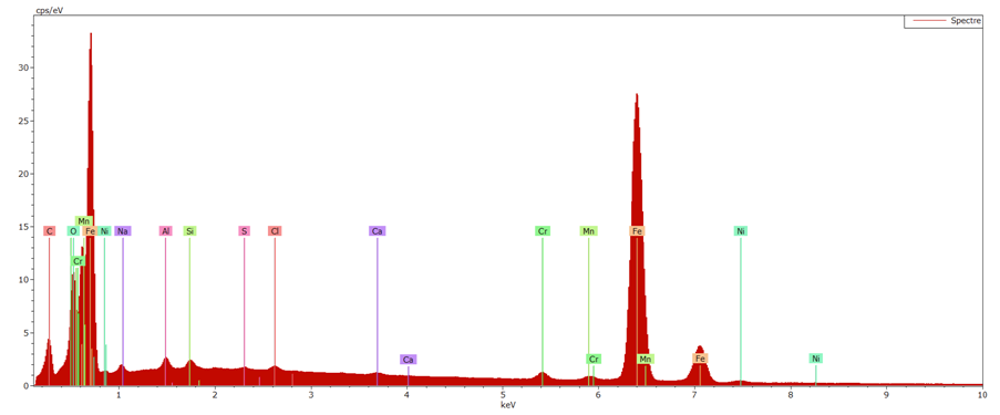 | Figure 1. Spectrum of steel AISI / SAE 3115 |
A chemical analysis by atomic absorption revealed the following components: 0.17% C, 0.74% Mn, 0.28% Si, 1.08% Cr, 1.24% Ni,0.76% Na, 0.47% Al, 0.20 Cl, 0.16% Ca, 0.03% S.A microscopic observation using a microscope REICHERT POLYVAR 2 on a sample previously polished and attacked with the nital (Alcohol+NHO3) has highlighted a ferrite-pearlite structure (Fig. 2).The more or less flattened grains in the radial direction of the specimen and perhaps elongated axially characterize a typical texture of burnishing (Fig. 2b). 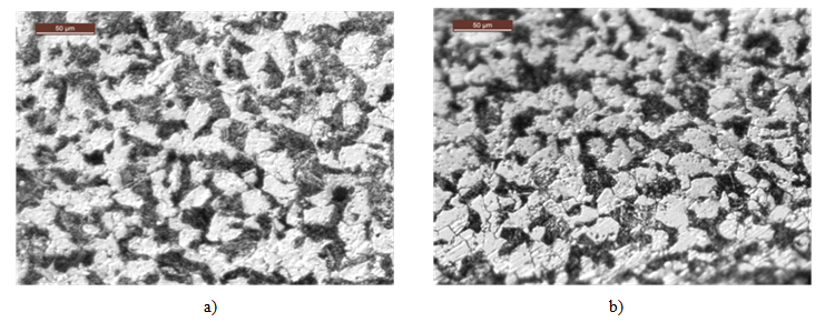 | Figure 2. Structure of the steel AISI / SAE 3115: a) after turning b) after burnishing |
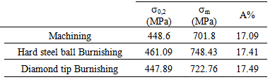
The mechanical characteristics of the material were evaluated using a tensile test performed on a cylindrical bar removed from the material in question. The test has to record the following properties (Table 1).Table 1. Tensile properties of AISI / SAE 3115
 |
| |
|
2.2. Preparation of Test Specimens
The specimens were machined from the representative of each material cylindrical rods. Their shapes and sizes are dictated by the standard NF EN 10002-1. Before the tensile test, the specimens have been as appropriate treatment burnishing or staying machining state.The measures of the roughness and hardness were performed respectively using a picture confocal microscope LEICA DCM3 capable of transcribing the signal received in Ra value and save the profile to any explored area and universal hardness tester LEICA Wetzlar Vickers indenter to measure the values of hardness Hv. The indentation load is 200 gr.Tensile tests were performed on a universal testing machine hydraulically MFL type VHP 600. The machine has a capacity of 60 tons is controlled by a computer with the software Zwick. The fixing of specimens is performed with the anchoring heads hydraulic containing interchangeable clamping wedges according to the type and dimensions of the test specimens. This machine has a range of speed of 1 to 300 mm / min.
3. Technique of Burnishing
The burnishing operation is performed on a lathe by means of a device the active part is a tip artificial diamond sometimes a hard steel ball (Fig. 3). The burnishing operation is similar to an operation of turning, at any time the SPD is provided by an effort exerted by the tool on the specimen in rotational movement. The advancing movement is assigned to the tool (Fig. 3). Burnishing is conducted under a regime taking into consideration the initial material hardness and rigidity of the system Machine Tool-specimen. This regime previously determined [11] is characterized by the following parameters:Burnishing force: P = 20 (kgf); Burnishing feed: f = 0.054 (mm. Rev-1); Burnishing speed: n= 560 (rev.min-1); Number o burnishing tool passes: i = 3 passes; Burnishing hard steel ball radius: r = 3mm and diamond ball radius: r = 2,5mm.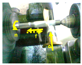 | Figure 3. Photo editing on a universal tower |
4. Experimental Results
The resulting physical and geometrical characteristics of burnishing are shown in Figure 4. This allows us to see and compare the influence of mechanical treatment by burnishing.It follows from these results that the treated superficial layers MST acquire a good surface appearance as a result of improving the roughness and themselves consoled of advantage in view of the increase in hardness (Fig. 4b).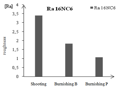 | Figure 4a. Characteristics of superficial: roughness Ra |
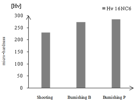 | Figure 4b. Characteristics of superficial: micro-hardness Hv |
The surface state is characterized by a profile in the ridges asperities resulting from lathe turning into the hollow after the passage of burnishing (Fig. 5).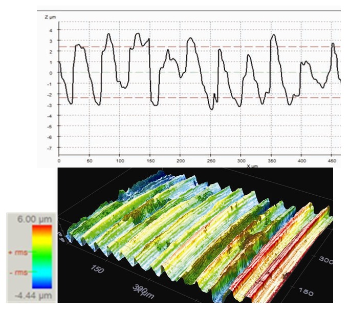 | Figure 5a. Example of profile roughness before shooting |
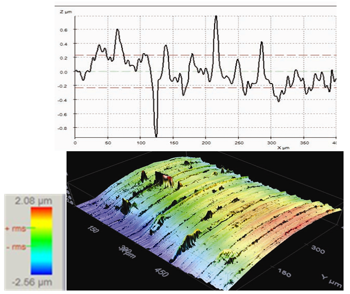 | Figure 5b. Example of profile roughness after burnishing |
The output response of the test is given in the form of conventional curve σ = f (ε). The figure 6 shows the behavior of the steel in tension.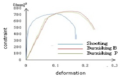 | Figure 6a. Stress-strain curves of AISI / SAE 3115: conventional |
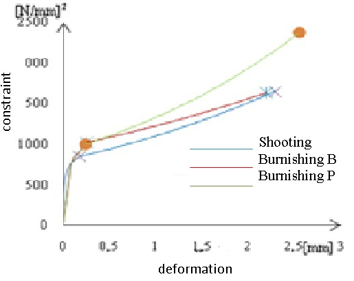 | Figure 6b. Stress-strain curves of AISI / SAE 3115: rationnel |
The elastic-plastic behavior reveals more of the linear elastic region that obeys Hook’s law plastic domain characterized by two sub-domains: The first defined by the yield strength and the tensile strength is that wherein the hardening material is consolidated. The second, which appears beyond the maximum stress, is the necking (Fig. 7a) in which the material is experiencing a plastic instability. 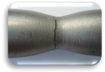 | Figure 7a. Phenomena tensile steel AISI / SAE 3115: necking |
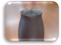 | Figure 7b. Phenomena tensile steel AISI / SAE 3115: final rupture |
The fractographic analysis reveals a break in nerve with an often inclined or mixed (Fig. 7b) Surface whose fracture surface reflects the ductile nature of the material tested. Ductility is a fundamental condition for the material to undergo mechanical surface treatment.
5. Modelling of Stress-strain Curves
5.1. True Stress and Strain
In a conventional traction curve, the breaking load is a conventional size since it includes only the initial section S0 (σ = σmax/S0). This prevents taken into account in the calculations of plasticity because the section is variable in time. For this purpose, we define a true stress (σv) which corresponds to the applied load related to the instantaneous section S = S (t). | (1) |
When deformations are infinitely small (→ε 0) and considering that the volume remains constant, we define: | (2) |
By aillor, the instantaneous deformation (relative) will be determined from small extensions dl at time t. In this case the relative deformation is:  | (3) |
In the field of homogeneous plastic deformation (before the onset of necking), the phenomenon of hardening can be evaluated on rational curves of traction: BC portion of a parabolic curve conventional (Fig. 5a) can be under certain empirical forms that connect the real constraint σv to εv the relative deformation. The term most commonly used is that of Ludwik [12]: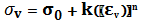 | (4) |
Where k σ0 and k are constants of the material and n is the coefficient of hardening.
5.2. Stresses and Strains Real
The appearance of the necking is to say, when the deformation is localized (generally in the middle of the test specimen) requires taking into account the effect of the stress concentration area of necking at each moment (Fig. 8).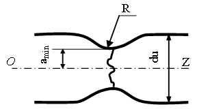 | Figure 8. Geometrical model of the necking zone |
The last value of the true stress σv(B) just before the start of the necking at start of the plastic instability and the corresponding true strain εv(B) are calculated after measuring the diameter of the test specimen in the area of the homogeneous deformation. | (5) |
And 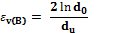 | (6) |
At the point of rupture, the true stress can be approximated taking into account the factor of stress triaxiality which reduces the value of the stress along the main axis of the specimen. The correction formula most commonly used is that of Bridgman [12]. This correction does not depend on the mechanical parameters of the material but only a geometrical factor a/R, gives the mean value of the tensile stress σx as a function of εv: 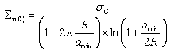 | (7) |
Where: amin is the radius R of curvature minimum section of the necked region. The corresponding true strain will:  | (8) |
The geometric parameters of the necked region were assessed (measured) from the profile of the specimen ruptured. The evaluation of all sizes was confirmed by a workshop microscope with an accuracy of 0.005mm. Finally, the field of plastic instability between points B and C was modeled by an exponential approximation. The results showing the corrected curves are plotted in Figure 6b.
5.3. Evaluation of the Hardening Coefficient
The hardening coefficient characterizes the true strain distributed (homogeneous) that a material can undergo and the ability to allocate uniformly this deformation for this purpose only the area of hardening has been considered. The hardening coefficient is obtained by linearization of rational curves by plotting in logarithmic coordinates.The slope of the curve directly gives the value of this coefficient. The director coefficient can be evaluated by linearization from a linear trend curve. Whose equation is used to deduce the coefficient k and go back to the relationship Ludwik. In logarithmic coordinates Ludwik relationship is written: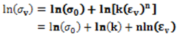 | (9) |
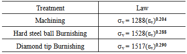
In This linear equation is defined as:  . For this purpose, the equation of the curve of hardening (LUDWIK relationship) can be evaluated as follows (Table 2):
Table 2. Hardening law steel AISI / SAE 3115
 |
| |
|
6. Results and Discussion
From the point of view technological aspect AISI / SAE 3115 adapts well to burnishing view that the roughness is remarkably improved. This result is due to the smoothing of the profile to the passage of burnishing with the diamond tip. The overall tensile behavior does not change since the plastic deformation does not affect the material volume but simply asperities roughness. It is only the superficial layers undergo damage. And the divergence of the stress-strain curves is solely the responsibility dispersions tests.A qualitative assessment of the area under the stress-strain curves left to see that the state of burnishing, the tensile curve covers an area larger than the state of lathe turning. So, after burnishing, specimen absorbs more energy to break and therefore it is more tenacious. However, for optimal system hardening coefficient increases as well as a device whose active part is a diamond tip or a steel ball. Providing up to 42 % when working with the diamond tip. The same effect is found for ball burnishing since the gain is (0288-0204)0,204=41.17%. In the absence of burnishing (machined specimen), consolidation of AISI/SAE 3115 is such that the micro-hardness of 229 Hv. Under the effect of this surface treatment with diamond tip micro-hardness increased to 284 Hv. This means that the material is further consolidates, a gain of 24% (Fig. 4b). This increase is due to the fact that burnishing created by plastic deformation of new dislocation sources that are activated in the superficial layers.
7. Conclusions
Burnishing is a mechanical surface treatment that combines several benefits to both steel grades studied. The application process promotes better roughness report the shooting. Also, it helps strengthen the superficial layers by hardening phenomena. Optimal effects are closely related to the processing parameters and the active part of the device. With an improvement of 68.26% over the roughness resulting from Burnishing at the tip, Burnishing can be defined as a finishing operation in the machining. With a gain of 24% over the rate of consolidation, this treatment is an effective method for the consolidation of materials.
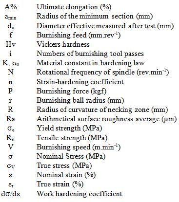
Nomenclature
References
| [1] | EL-AXIR M. H. An investigation into roller burnishing, Int. J. Mach. Tools Manufact. (40) (2003) 1603-1617. |
| [2] | ZHANG P. Lindemann J. Effect of roller burnishing on the high cycle fatigue performance on the high-strength wrought magnesium alloy AZ80, Scripta Mater. (52) (2005) 1011-1015. |
| [3] | MENDAR A. C. E. La technique du galetage, Métaux et déformation 47 (1978) 46-52. |
| [4] | HAMADACHE H. Laouar L. Chaoui K. Zeghib N. E. Characteristics of Rb 40 steel superficial layer under ball and roller burnishing, J. Mater. Process. Technol. (180) (2006) 130-136. |
| [5] | LOPEZ DE LACALLEL. N. Lamikiz A. Munoa J. Sanchez J.A., Quality improvement of ball-end milled sculptured surfaces by ball burnishing, Int. J. Mach. Tools Manufact. (45) (2005) 1659-1668. |
| [6] | LAOUAR L. Hamadache H. Saad S. Bouchelaghem A. Mekhilef S. Mechanical surface treatment of steel-Optimization parameters of regime, Phy. Proc. (2) (2009) 1213–1221. |
| [7] | KORZYNSKI M. Pacana A. Centerless burnishing and influence of its parameters on machining effects, J. Mater. Process. Technol. (9) (2010) 1217-1223. |
| [8] | BASAK H. Goktas H. H. Burnishing process on al-alloy and optimization of surface roughness and surface hardness by fuzzy logic, Mat. Des. (30) (2009) 1275-1281. |
| [9] | LOPEZ DE LACALLE L. N. Rodriguez A. Lamikiz A. Celaya A. Alberdi R. Five-axis machining and burnishing of complex parts for the improvement of surface roughness, Mater. Manuf. Proces. (26) (2011) 997–1003. |
| [10] | AVILLES R. Albizuri J. Rodriguez A. Lopez de lacalle L. N. Influence of low-plasticity ball burnishing on the high-cycle fatigue strength of medium carbon AISI 1045 steel, Int. J. Fatigue (55) (2013) 230-244. |
| [11] | RODRIGUEZ A. Lopez de lacalle L. N., Celaya A. Lamikiz A. Albizuri J. Surface improvement of shafts by the deep ball-burnishing technique, Surf. Coat. Technol. (206) (2012) 2817-2824. |
| [12] | HASSAN A. M. The effect of ball and roller burnishing on the surface roughness of some non- ferrous metals, J. Mater. Process. Technol. (72) (1997) 385-391. |
| [13] | HAMADACHE H. Laouar L. Chaoui K. Comportement mécanique d’un acier au carbone sous l’effet du brunissage ou du galetage, Mécanique & Industrie, (9) (2008) 183-191. |
| [14] | GRZESIK W. Zak K. Modification of surface finish produced by hard turning using superfinishing and burnishing operations, .J Mater. Process. Technol. (212) (2012) 315-322. |
| [15] | HAMADACHE H. Amirat A. Chaoui K. Effect of diamond ball burnishing on surface characteristics and fatigue strength of XC55 steel, Int. Review Mech. Eng. (1) (2008) 40-48. |
| [16] | ZAY K. Maawad E. Brokmeier H. G. Wagner L. Genzel Ch. Influence of mechanical surface treatments on high cycle fatigue performance of TIMETAL 54M, Mater. Sci. Eng. A (528) (2011) 2554-2558. |
| [17] | MAAWED E. Brokmeier H. G. Wagner L. Sano Y. Genzel Ch. Investigation on the surface and near-surface characteristics of Ti-2.5Cu after various mechanical surface treatments, Surf. Coat. Technol. (205) (2011) 3644-3650. |
| [18] | SHIOU F. J. Hsu C.C. Freeform surface finish of plastic injection mold by using ball burnishing process, J. Mater. Process. Technol. (140) (2003) 248-254. |
| [19] | LOW K. O. Wong K. J. Influence of ball burnishing on surface quality and tribological characteristics of polymers under dry sliding conditions, Tribol. Int. (44) (2011) 144-153. |
| [20] | SALAHSHOOR M. Guo Y. B. Surface integrity of biodegradable magnesium–calcium orthopedic implant by burnishing, J. Mech. Behav. Biomed. Mater. (4) (2011) 1888–904. |
 Abstract
 Reference
 Full-Text PDF
 Full-text HTML