-
Paper Information
- Paper Submission
-
Journal Information
- About This Journal
- Editorial Board
- Current Issue
- Archive
- Author Guidelines
- Contact Us
International Journal of Mechanics and Applications
p-ISSN: 2165-9281 e-ISSN: 2165-9303
2014; 4(1): 8-12
doi:10.5923/j.mechanics.20140401.02
Experimental Investigation of the Height Effect of Water Savonius Rotors
 Abstract
 Reference
 Full-Text PDF
 Full-text HTML
Ibrahim Mabrouki, Zied Driss, Mohamed Salah Abid
Laboratory of Electro-Mechanic Systems (LASEM), National School of Engineers of Sfax (ENIS), University of Sfax, B.P. 1173, Road Soukra km 3.5, 3038 Sfax, Tunisia
Correspondence to: Zied Driss, Laboratory of Electro-Mechanic Systems (LASEM), National School of Engineers of Sfax (ENIS), University of Sfax, B.P. 1173, Road Soukra km 3.5, 3038 Sfax, Tunisia.
| Email: |  |
Copyright © 2014 Scientific & Academic Publishing. All Rights Reserved.
Savonius rotor is simple in design and easy to fabricate at a lower cost. The basic driving force of Savonius rotor is drag. Hence, the advancing blade with concave side facing the water flow would experience more drag force than the returning blade, thus forcing the rotor to rotate. In this work, we are interested on the study of the effect of the Savonius rotor height on the hydrodynamic characterisations. In particular, we present a detailed description of the test section and the various manipulations made to develop the hydrodynamics characteristics of the water Savonius rotor such as power, torque and its coefficients.
Keywords: Savonius rotor, Test bench, Height effect, Power, Global characteristics
Cite this paper: Ibrahim Mabrouki, Zied Driss, Mohamed Salah Abid, Experimental Investigation of the Height Effect of Water Savonius Rotors, International Journal of Mechanics and Applications, Vol. 4 No. 1, 2014, pp. 8-12. doi: 10.5923/j.mechanics.20140401.02.
Article Outline
1. Introduction
- Environmental issues as typified by global warming become conspicuous in recent years. It is obvious that using natural energy effectively leads achieving sustainable energy. The hydropower should occupy the attention of electric power generating systems as it is clean and renewable energy source with highest density, in cooperation with the wind and the solar powers [1]. Most of hydropower is generated by the large-scale hydroelectric plant. Some have suggested that dam constructions can lead to the tremendous environmental damages [2]. Water current turbines generate electricity using the kinetic energy of natural water resources using different types of rotors. These rotors are fixed to a structure on the riverside or on floating pontoons. Hydro-kinetic turbine electricity generation is mainly aimed for rural use at sites remote from existing electricity grids. It is a useful tool for improving the quality of life of people in these locations and for stimulating local economies [3]. These turbines also can be considered for the wide variety of application like tides, marine currents, channel flows and water flows from industrial processes. Different designs of water current turbine are available for the extraction of energy from the river water or canals. Literature suggests that there is a gaining of popularity for water turbines. Horizontal axis turbines are common in tidal energy converters and majority of marine current turbines are horizontal axis turbine. They are very similar to modern day wind turbines from design and structural point of view. In the vertical axis turbines domain, the Darrieus turbines, Savonius turbine and Gorlov helical water turbines are generally used. The Gorlov turbine has the blades of helical structure. Gorlov proposed a new helical turbine to convert kinetic energy of flowing water into electrical or mechanical energy [4]. The advantage of this device is that it reduces the relative diameter of the rotor while simultaneously increasing the length of the blade. Savonius turbines are drag type devices as drag force is the main driving force for this type machine [5]. Savonius rotor is made by cutting the cylinder into two halves along the central plane and then making it into ‘S’ shapes [6-10]. Although Savonius rotor is simple in design and construction, but still not as popular as compare to the horizontal axis water turbine due to its poor performance. Many researchers have adopted various techniques to maximize the performance and improve the starting torque characteristics of Savonius rotor with water as working medium [11-14]. These include use of guide vanes, V-plate deflector plate, deflector plate and blade with flat and circular shielding. Some of these techniques require change in design of blade and other involves supplementary devices addition to the system. The direction of the wind is unpredictable [15]. Hence, the proper positioning of the deflector plate with the change in the direction of the wind becomes difficult. However, deflector plates would work better in canals and rivers because of the fixed direction of the water. Savonius runner has been used mainly for a wind power and tidal-wave power generation. Many studies of Savonius rotor consist on the numerical simulations of the flow field, and the investigations of the guide vanes effect around a runner [16]. Attempts have been made for the performance improvement of low-efficiency Savonius runners by optimizing both runner shape and collector [17-20].According to these anteriors investigations, it has been noted a paucity on the study of the water Savonius rotors. For thus, we are interested in the experimental characterization of water Savonius rotors using a hydraulic test bench equipped with a specific instrumentation. A detailed description of the test section and the various manipulations was made to present the hydrodynamic characteristics of the Savonius rotors such as power, torque, and its coefficients. Particularly, we are interested on the study of the water Savonius rotors height effect.
2. Materials and Method
- The present investigation involved the study of two water Savonius rotor. Experimental tests for determination of global characteristics such as power, dynamic torque, and its coefficients required the use of a hydrodynamic test bench. Otherwise, the test bench should be equipped with a specific instrumentation for the development of various experimental tests necessary in the laboratory scale.
2.1. Hydrodynamic Test Bench
- The hydrodynamic test bench consists on an intake, a control gate, a penstock, a canalization, a turbine, a test section, an outflow and a pump. The collector is a parallelepiped box where the water flows inside a square tank located above the test section shape on a closed circuit. Another square tank placed in the downstream allows the return of the water in the first tank using pumps excited by two induction motors with two pairs of poles with a maximum speed of 1400 rpm. The penstock is the converging portion in which the flow is gradually accelerated from a low speed until the desired value in the test section through a 45° angle. Using the water Savonius rotor, the mechanical translation energy of the water is transformed into rotation mechanical energy [21-23].
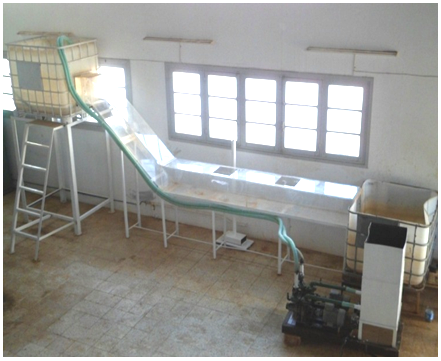 | Figure 1. Hydrodynamic test bench |
2.2. Water Savonius Rotors
- In this experimental investigation, we are interested on the study of two Savonius rotors with heights equals to H=200 mm and H=100 mm (Figure 2). In these conditions, the Savonius rotor consists of two buckets assembled on a common axis and secured at an angle of 180°. The diameter of each buckets is equal to d=100 mm. However, the Savonius rotors diameter is equal to D=190 mm.
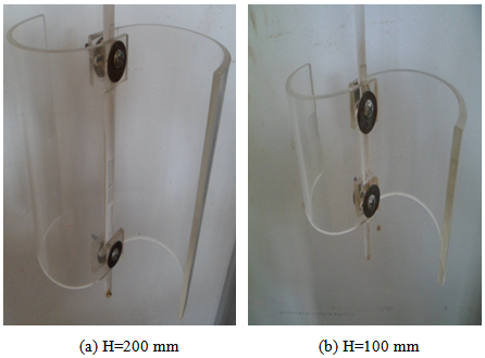 | Figure 2. Water Savonius rotor |
2.3. Measure Method
- The dynamic torque exerted on the rotor shaft was measured with a DC generator which transforms the torque on its axis at an electrical current. For that the generator, coupled to the dynamometer RZR-2102 model, display simultaneously the shape speed and the dynamic torque. This dynamometer has been used to provide mechanical power to the generator which delivers an electric current in a resistive load. To measure the rotational speed of the Savonius rotor, a digital tachometer CA-27 model was used. In these conditions, the optical sensor provides results without disturbing the rotor movement. This is made feasible since the test section is made on a transparent plexiglass (Figure 3).
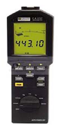 | Figure 3. Tachometer type 1725 |
 | (1) |
 torque (N m)P: power (W)
 rotation speed (rpm)The power coefficient Cp of water Savonius rotors is defined by:
  | (2) |
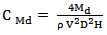
 power coefficient A: swept area of the rotor (m2)ρ: density of fluid (kg m-3)V: water speed (m/s)In case of water Savonius rotor the swept area is equal to:
 | (3) |
 | (4) |
3. Experimental Results
- In a first trial, the turbine was placed in the center of the turbine collector of width 400 mm and length 400 mm, but the impeller does not rotate. In a second trial, the turbine turns when it is placed at x=100 mm from the center. So, the comparison between these cases confirms that the second case is more adequate.
3.1. Power
- In figure 4 are superposed the different results for all considered configurations. According to these results, the power variation shows a parabolic shape. The first curve corresponds to the Savonius rotor height H=100 mm. According to these results, we find that the maximum value of the power is equal to P=13.03 W for a rotation speed Ω=685 rpm. However, for the Savonius rotor height H=200 mm, the maximum value is equal to P=6.667 W for the rotation speed Ω=570 rpm. According to these results, we find that the best values of the power corresponds to the Savonius rotor height equal to H=100 mm. Indeed, the Savonius rotor of H=200 mm admits low values. In these conditions, the highest Savonius rotor is considered as an obstacle behind the water rotor. However, the lowest Savonius rotor appears more preferment in the used test section.
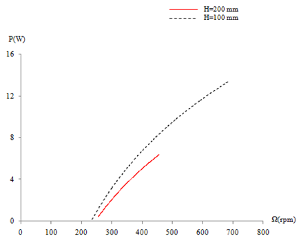 | Figure 4. Variation of the power for different Savonius rotors |
3.2. Dynamic Torque
- In figure 5 are superposed the different results for all considered configurations. According to these results, the variation of the dynamic torque shows a parabolic shape. The first curve corresponds to the Savonius rotor height H=100 mm. The maximum value of the dynamic torque Md is equal to Md=0.21 N.m for the rotation speed equal to Ω=685 rpm. However, for the Savonius rotor height H = 200 mm, the maximum value Md=0.14 N.m is obtained for the speed rotation equal to Ω=470 rpm. For thus, we find that the best values of the dynamic torque corresponds to the Savonius rotor height equal to H=100 mm. Indeed, the Savonius rotor of H=200 mm admits low values. Then, the highest Savonius rotor is considered as an obstacle behind the water turbine. However, the lowest Savonius rotor appears more preferment in the used test section.
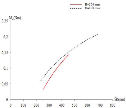 | Figure 5. Variation of the dynamic torque for different Savonius rotors |
3.3. Power Coefficient
- In figure 6 are superposed the different results for all considered configuration. According to these results, the variation of the power coefficient shows a parabolic shape. In the first curve corresponding to the Savonius rotor height H=100 mm, we find that the maximum value of power coefficient is equal to Cp=0.19 for a specific speed equal to λ=3.027. However for the Savonius rotor height H=200 mm, the maximum value is equal to Cp=0.047 for the specific speed equal to λ=1.84. According to these results, we find that the best values of Cp corresponds to the Savonius rotor height equal to H=100 mm. However, the Savonius rotor of H=200 mm admits low values. In these conditions, the highest Savonius rotor is considered as an obstacle behind the water Savonius rotor. For thus, the Savonius rotor with a height equal to H=100 mm appears more efficient in the used test section.
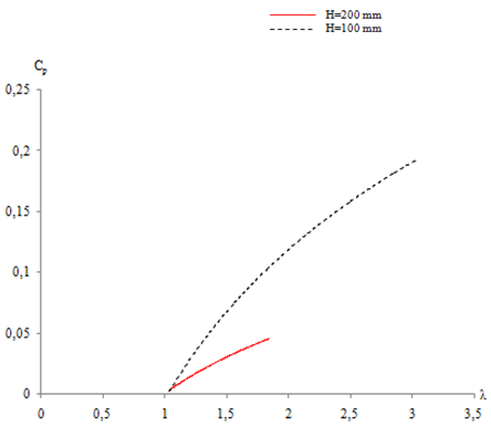 | Figure 6. Variation of the power coefficient for different Savonius rotors |
3.4. Dynamic Torque Coefficient
- In figure 7 are superposed the different results for all considered configurations. According to these results, the variation of the dynamic torque coefficient CMd shows a parabolic shape. For the first curve corresponding to the Savonius rotor height H=100 mm, we find that the maximum value of the dynamic torque coefficient is equal to CMd=0.155 for a specific speed equal to λ=3.02. However, for the Savonius rotor height H=200 mm, the dynamic torque coefficient decreases. The maximum value is equal to CMd=0.024 for the specific speed λ=1.84. In these conditions, the highest Savonius rotor is considered as an obstacle behind the water turbine. Then, we can confirm that the dynamic torque coefficient of the Savonius rotor increases in the used test section with the decrease of the Savonius rotor height.
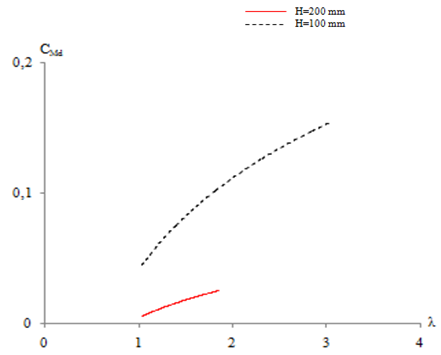 | Figure 7. Variation of the dynamic torque coefficient for different Savonius rotors |
4. Conclusions
- In this paper, we are interested on the global characteristics of two water Savonius rotors. In particular, we have studied the rotor height effect on the variation of the power, the dynamic torque and its coefficients depending on the rotational and the specific speed. In this study, we confirm that these parameters increase in the used test section with the decrease of the Savonius rotor height. The highest Savonius rotor is considered as an obstacle behind the water turbine. Indeed, the lowest water Savonius rotor appears more preferment in the used test section.In the future, we suggest the addition of a deflector to improve the rotors performance.
Nomenclature
- A: swept area of the rotor (m2)CMd: coefficient of torqueCp: coefficient of powerD: diameter of the rotor (m)H: height of the rotor (m)Md: dynamic torque (N.m)P: power (W)V: water speed (m/s)ρ: density of fluid (kg m-3)
ACKNOWLEDGEMENTS
- The authors would like to thank the Laboratory of Electro Mechanic Systems (LASEM) members for the financial assistance.