Shengyong Zhang
College of Engineering and Technology, Purdue University North Central, Westville Indiana, 46391, USA
Correspondence to: Shengyong Zhang, College of Engineering and Technology, Purdue University North Central, Westville Indiana, 46391, USA.
| Email: |  |
Copyright © 2012 Scientific & Academic Publishing. All Rights Reserved.
Abstract
Thickness of stamped-sheet steel panels that comprise the majority of a modern vehicle’s body-in-white (BIW) has a direct effect on vehicle dynamic performance. Despite the ongoing increase in workstation processor speed, computational time still creates limitations on performing modal calculations. These limitations are even more pronounced than for static and quasi-static structural calculations. Gauge sensitivity methodologies allow a designer to make quick, accurate estimates of structure natural frequencies based upon only a few baseline analyses. This paper performs gauge sensitivity analysis to assess changes in the vehicle body natural frequencies due to changes in material thickness. Corresponding algorithm for computational implementation is presented. Gauge sensitivity results of rods in longitudinal vibration, beams in transverse vibration, and shafts in torsional vibration are provided to validate the proposed gauge sensitivity method. Application studies are conducted to calculate changes in the natural frequencies of a commercial light duty truck cab and its components when subjected to thickness modifications. Gauge sensitivity results are compared to finite element based results and the agreement is good.
Keywords:
Gauge Sensitivity, Natural Frequency, Vehicle Body-in-white, Weight Reduction
Cite this paper: Shengyong Zhang, Application of Gauge Sensitivity for Calculating Vehicle Body Natural Frequencies, International Journal of Mechanics and Applications, Vol. 3 No. 6, 2013, pp. 139-144. doi: 10.5923/j.mechanics.20130306.01.
1. Introduction
Lightweight vehicle design has been motivated by a need to reduce fuel consumption without compromising vehicle’s noise, vibration and harshness (NVH) performance characteristics. Improving fuel efficiency in all vehicle classes has been made even more acute by recent increase in energy prices and requirement for low greenhouse gas emission. The lighter a vehicle could be, the less energy would be desired for propulsion, which in turn permits the use of smaller, more efficient powertrain components. The vehicle’s BIW typically accounts for one-third of the total weight and is therefore a prime target for weight reduction. A 10% reduction in a vehicle’s BIW can lead to secondary weight (e.g. chassis, powertrain) reductions of 5-7% of vehicle primary weight, and a 10% reduction in mass yields an increasing in the range of 2-5% in fuel economy[1], which is quite significant.The availability of high-strength steel (HSS) with much higher yield strengths[2, 3], as well as an array of new manufacturing technologies (e.g. laser welding technology [4], hydroforming[5], and tailor-welded blanks[6]) are being adopted by automotive industries, giving designers the option of incorporating more thin-walled components in their vehicles. The fundamental advantage of thin-walled structures as found in vehicle bodies is that the material is efficiently loaded, resulting in uniformly distributed normal and shear stresses. These uniform stress distributions in turn yield high stiffness-to-weight ratios.However, such thickness decreases may adversely affect associated NVH characteristics, resulting in higher levels of vehicle body vibration and interior cabin noise. The vibration environment is one of the important criteria by which people judge the design and construction “quality” of a vehicle. To improve the overall ride performance, it is necessary to mitigate the dynamic response of vehicle body in response to excitation from either road roughness or on-board sources (tire/wheel assembly, powertrain and engine, for example). Most importantly, it is desirable to avoid excessive vibration due to resonance. This can be achieved by designing the vehicle BIW so that its natural frequencies are out of the range of dynamic excitations.Both structural dynamic modification (SDM) method and sensitivity method have been employed to study the effects of design parameter modifications on vehicle BIW dynamic performances. The former determines the changes in structural modal properties due to modifications of structural properties (e.g. mass, stiffness, and damping coefficient) using either test or finite element data as the basis. The latter characterizes the sensitivity of dynamic quantities to interested design variables, focusing on the derivatives of system eigenvalues and eigenvectors with respect to structural parameters.Despite the ongoing increase in workstation processor speeds, computational cycle times still create limitations on using finite element models for performing modal calculations. These limitations are more pronounced than for static or quasi-static structural calculations. Gauge sensitivity indices are developed for assessing the effect of material thickness changes on vehicle BIW performance [1,7]. They allow quantitative consideration of the tradeoffs between weight reduction and NVH performance resulting from design modification involving thickness changes. Gauge sensitivity indices are originally derived by approximating a number of stiffness-related structural parameters (area moment of inertia, bending stiffness, torsional stiffness, for example) as a power function of the sheet metal thickness. The derivation also suggests the algorithm for computational implementation, in which the stiffness-based parameters are used as the basis for determining gauge sensitivity. This paper presents a method for calculating structural gauge sensitivity indices based upon natural frequencies and establishes corresponding analysis algorithm. Analytical gauge sensitivity analyses are performed for longitudinally vibrating rods, transversely vibrating beams, and torsionally vibrating shafts to validate the proposed gauge sensitivity method. The work concludes with case studies illustrating application of gauge sensitivity technique for assessing vehicle body natural frequencies.
2. Gauge Sensitivity for Natural Frequency Analysis
2.1. Natural Frequency-based Gauge Sensitivity Indices
While mathematical derivations for gauge sensitivity indices are beyond the scope of this article, the application equations are summarized here. Most modern automobiles and trucks have body structures comprised of stamped or bonded panels connected with combinations of fasteners, resistance welds and bonding. For a stiffness-proportional parameter, f(t), that is a function of panel thickness t, we can express the gauge sensitivity λ as: | (1) |
or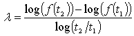 | (2) |
λ in the above equations governs the sensitivity of the parameter f(t) to panel thickness and is referred to as the “gauges sensitivity”. We can make the following conclusions regarding λ:● Eq. 1, the tangent method, is applied to calculate λ when the stiffness-related parameter f(t) can be analytically or numerically expressed as a function of sheet metal thickness t.  here represents the first derivative of the parameter with respect to thickness. λ can be graphically interpreted to be the ratio between the slope of the tangent line to f(t) at the operating point to the slope of the secant line from the origin to the operating point.● Eq. 2, the secant method, is an alternative approach (in discrete form) for calculating λ using two known values of the thickness (one is slightly less than the nominal thickness and the other is slightly more than the nominal thickness) and the corresponding parameter values.● The nonlinear nature of the stiffness-related parameter will result in variable λ at different thickness. However, for realistic BIW gauge modification range, λ can be assumed constant and be applied to investigate the influence of thickness modifications on the response parameter f(t).With known and constant λ, the following Eq. 3 can be used to estimate changes in the parameter f due to a uniformly proportional gauge modification from t1 to t2. The term α in the equation is defined as gauge modification factor, such that t2 = αt1.
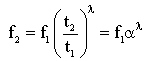 | (3) |
Except of stiffness-related parameters, gauge sensitivity indices can also be determined based upon structure’s natural frequencies. The ith order natural frequency, ωi, of a vehicle body structure can be calculated from corresponding modal stiffness (Ki) and modal mass (Mi): | (4) |
Since Ki is a linear function of tλ and Mi is a linear function of t, Eq. 4 may be rewritten as: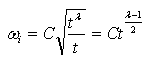 | (5) |
Here C is a constant. Taking derivative of Eq. 5 with respect to thickness and eliminating the constant C yields: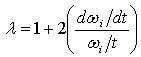 | (6) |
Eq. 6 can be used to calculate λ when the frequency ωi and its derivative dωi/dt can be expressed as functions of thickness t.λ can be alternatively calculated in discrete form by fitting a straight line between a known pair of natural frequency /thickness values evaluated at two nearby points to the original sheet thickness. Corresponding to thickness change from t1 and t2 (t2 = αt1), the ith order natural frequency will have its value altered according to Eq. 5: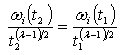 | (7) |
Taking the logarithm of Eq. 7 and solving for λ, the gauge sensitivity based on the ith order natural frequency of the structure may thus be calculated as: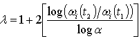 | (8) |
For many structures and design cases, 10 % thickness increase and 10% thickness reduction (t2 = 1.1t0 and t1 = 0.9t0 where t0 is the original sheet thickness of the structure) work well for calculating λ.With its value being determined by either Eq. 6 or Eq. 8, λ can then be used to calculate changes in the ith order natural frequency due to a uniformly proportional gauge modification of the structure from t1 to t2 by: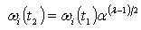 | (9) |
2.2. Sample Applications of λ
To illustrate application of the proposed technique, consider the vibration of a rod in the longitudinal direction. The one-dimensional vibration is controlled by its wave equation involving both spatial and temporal derivatives. The natural frequencies of the rod can be solved analytically with given boundary and initial conditions. The fixed-free configured rod of length for example, has the natural frequencies evaluated by[8]:
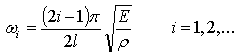 | (10) |
where E is the material’s modulus of elasticity and ρ is the material density.  defines the velocity of propagation of the displacement (or stress wave) in the longitudinal direction in the rod.Eq. 10 denotes that the ith order natural frequency of a hollow rod is exclusively determined by its length and material properties (i.e., E and ρ). Independence of its natural frequencies with respect to thickness results in λ value of unity from Eq. 6. Gauge sensitivity value of unity implies the natural frequency is insensitive to thickness. In other words, the modal stiffness and modal mass related to this natural frequency change at the same rate when thickness is being changed. Modifications to thickness of such structures may not be a strategy for improving modal properties.Another example is based on the bending vibration of a cantilever beam with hollow circular cross section. Its natural frequency associated with the ith order vibration mode is determined by:
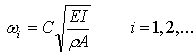 | (11) |
where C is a constant, I is the area moment of inertia about the beam’s neutral axis, A is the cross sectional area, and E and ρ are the material’s modulus of elasticity and density, respectively. Consider a beam with inner radius of r, wall thickness of t, and length of I and A can be evaluated by
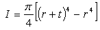 | (12) |
and 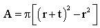 | (13) |
Substituting Eqs. 12 and 13 in Eq. 11 yields ωi as a function of t. λ is then calculated by Eq. 6: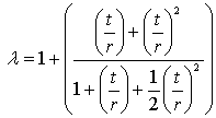 | (14) |
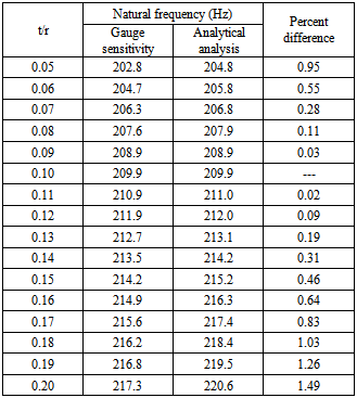
If plotting λ, we see that the values of λ range from 1.0 for very small thickness values, increase monotonously with increasing thickness to 3.0 for large thickness, see Figure 1. Consider a cantilever beam with inside radius of 0.1m, thickness of 0.01m, and length of 1m. Without loss of generality, we take its first natural frequency ω1(t) as an example in the following analysis. Expressing ω1(t) as a function of thickness and substituting it in Eq. 6 yields λ value of 1.1. λ may be considered as constant if thickness modification of the thin-walled beam is made nearby the original thickness. With known and constant λ, we can evaluate the changes in the first order natural frequency with respect to thickness. The results corresponding to thickness ranging from one-half of the original thickness (α = 0.5) to double thickness (α = 2) are listed in Table 1. The gauges sensitivity results are in good agreement with corresponding analytical results.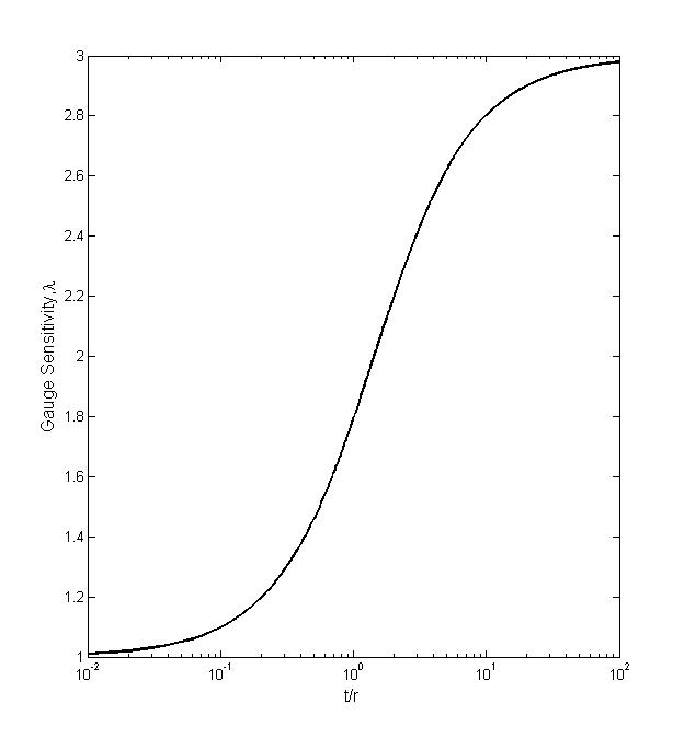 | Figure 1. Variation of cantilever beam gauge sensitivity with thickness |
Table 1. Changes in the first order natural frequency of a cantilever beam with respect to thickness modifications for the following given data: = 1m, r =0.1m, E = 200GPa, and ρ = 7850kg/m3 (the natural frequency at t/r = 0.1 is used as reference value)
 |
| |
|
Finally gauge sensitivity is applied to shafts in torsional vibration. In this case the vibration occurs in an angular direction. The rotation of a shaft about its center axis is a function of both the position along the length of the shaft and the time. Eq. 4 can still be used to estimate natural frequencies by replacing Ki and Mi with torsional stiffness and polar moment of inertia of the shaft, respectively. For a hollow shaft with circular cross section, the natural frequencies is calculated analytically by the following Eq. 15 if the shaft is fixed at one end and free at the other end[8]: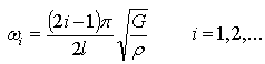 | (15) |
where  is the length of the shaft, G and ρ are material’s shear modulus and density, respectively. Similar to that of longitudinally vibrating rods, the torsional natural frequencies of hollow circular shafts are independent of cross section thickness, resulting in λ value of unity. It indicates that modifications to thickness of such shafts do not affect torsional natural frequencies.For a hollow shaft of other than circular cross section, we can replace
 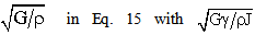 for calculating torsional natural frequencies, where γ is the cross section- associated torsional constant and J is polar mass moment of inertia of the shaft per unit length. A thin-walled rectangular cross section with inside width of w and height of h, for example, will have its γ and J calculated by
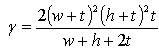 | (16) |
and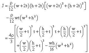 | (17) |
Both γ and J depend on thickness, and so does ωi(t). Substituting ωi(t) in Eq. 6 will yield λ, a measure of the sensitivity of the ith order torsional natural frequency of the rectangular hollow shaft relative to wall thickness. Determination and application of λ for torsional vibrations are in the same manner as that for rods and beams.
3. Application Studies
3.1. B-pillar to Rocker Joint
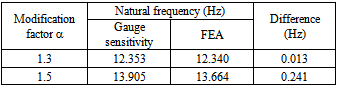
A vehicle body joint is traditionally defined as the intersection of two or more beam-like load-carrying members, such as the front hinge pillar to rocker joint, B-pillar to rocker joint, C-pillar to roof rail joint, etc. Body joints are compliant and their flexibility affects significantly vehicle body dynamic behaviour. Reference[7] presents application of the gauge sensitivity technique to the B-pillar to rocker joint of a light-duty truck and demonstrated the effect of modifications to the panel thickness on the joint stiffness. The same joint model is used in this paper to demonstrate application of the proposed natural frequency- based gauge sensitivity for evaluating changes in the joint natural frequencies due to changes in panel thickness.Figure 2a shows the B-pillar to rocker joint which is comprised of external and internal metal sheets fasten together by spot welds along the boundary edges. Figure 2b shows the joint finite element (FE) model in which all the peripheral nodes at both rocker cuts are fixed. The gauge sensitivity analysis is performed as follows: perform FE modal analysis at the original joint thickness configuration to identify the interested vibration mode (fundamental bending in the In/Out direction, for example) and corresponding natural frequency value. Perform other two baseline FE modal analyses using two known values of the joint thickness (one is 10% less than the nominal thickness and the other is 10% more than the nominal thickness). Calculate λ using the secant method (Eq.8). With λ determined, the changes in the natural frequency of this vibration mode due to changes in panel thickness can be estimated by using Eq. 9. For the B-pillar to rocker joint, we are interested in the two fundamental bending modes (one in the In/Out direction and the other in the Fore/Aft direction) and the fundamental torsional mode about the pillar direction. We make use of the three λs associated with each of these fundamental vibration modes and estimate changes in the natural frequency when the thickness is increased by 30 and 50%, separately. The results are listed in Tables 2 to 4 and compared with FE-based results. They are in good agreement.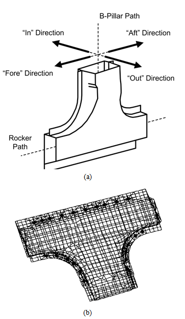 | Figure 2. (a) B-pillar to rocker joint and (b) joint finite element model |
Table 2. Fundamental bending natural frequency in the In/Out direction for different thickness modifications of the joint
 |
| |
|
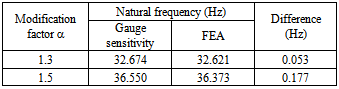
Table 3. Fundamental bending natural frequency in the Fore/Aft direction for different thickness modifications of the joint
 |
| |
|
Table 4. Fundamental torsional natural frequency about B pillar path for different thickness modifications of the joint
 |
| |
|
3.2. Light-duty Truck Cab
The gauge sensitivity technique as described is independent of vehicle type. A light-duty truck cab is used for application study, see Figure 3. Reference[7] presented gauges sensitivity results of the same cab model from bending and torsional stiffness point of view. Except of stiffness, the natural frequencies associated with critical vibration modes are also an important consideration in the vehicle BIW design. In this study, we focus on the fundamental natural frequencies, since lower order modes have a pronounced effect on the ride and handling performance and NVH characteristics.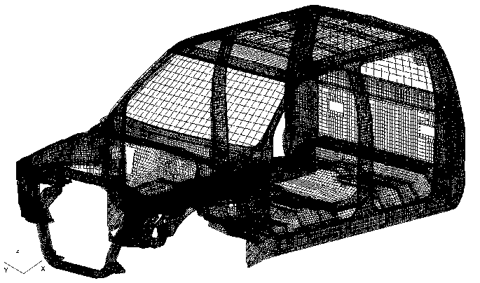 | Figure 3. FEA model of a light-duty truck cab |
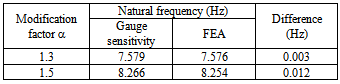
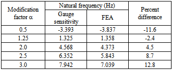
Gauge sensitivity analysis for the cab is in a manner identical to that for the B-pillar to rocker joint. Without loss of generality, we analyze the fundamental bending vibration about y-axis. The value of λ associated with this bending mode is calculated to be 1.86 through two baseline FE modal analyses. We then make use of the determined λ to estimate changes in the natural frequencies when the cab thickness is modified by a factor of 0.5, 1.25, 2.0, 2.5, and 3.0, separately. To check the accuracy of the foregoing gauge sensitivity results, FE modal analysis is performed at each modified thickness configuration. The results are consistent with each other, see Table 5.Table 5. Changes in the natural frequency of the fundamental bending mode about y-axis due to changes in the cab thickness, calculated by gauge sensitivity analysis and finite element analysis
 |
| |
|
4. Conclusions
The fundamental concept of gauge sensitivity originates from approximating stiffness-related structural parameters as a polynomial function of the sheet metal thickness. This paper puts forward gauge sensitivity indices based upon structure’s natural frequencies. The computational procedure is provided for determining λ values and calculating natural frequency changes resulting from thickness modifications. A series of analytical examples, including longitudinal vibration of rods, bending vibration of beams, and torsional vibration of shafts are presented to validate gauges sensitivity results. A light-duty truck cab and its B-pillar to rocker joint are utilized in the application case studies. All gauge sensitivity results are compared to either analytical results or FE-based results and the agreement is good. Future research includes applications of gage sensitivity to non-body vehicle structures. For example, truck frames and cross members are often fabricated from stamped or rolled members and fall into this architecture category. It should be possible to employ gauge sensitivity to these components with little or no modifications to the methodologies, however, these components may yield gauge sensitivity values quite different from those seen for body structures.
References
| [1] | Patton, R. and Edwards, M. (2002) ‘Estimating weight reduction effects of material substitution on joints with constant stiffness’, SAE paper number 2002-01-0368. |
| [2] | Martin, D.C. (1997) ‘ULSAB: a progress report’, Advanced Materials & Processes, Vol.152, No. 3, pp.72-74. |
| [3] | Prater, G., Azzouz, M., Furman, V., Shahhosseini, A. and State, M. (2002) ‘Use of FEA concept models to develop light-truck cab architectures with reduced weight and enhanced NVH characteristics’, SAE paper number 02M-145. |
| [4] | Schubert E, Klassen M, Zerner I, Walz C, Sepold G. (2001) ‘Light-weight structures produced by laser beam joining for future applications in automobile and aerospace industry’, Journal of Materials Processing Technology, Vol. 115, pp. 2–8. |
| [5] | Teng BG, Yuan SJ, Wang ZR. (2001) ‘Experimental and numerical simulation of hydroforming toroidal shells with different initial structure’, International Journal of Pressure Vessels and Piping, Vol. 78, pp. 31–34. |
| [6] | Kusuda, H., Takasago, T.and Natsumim F. (1997) Formability of tailored blanks. Journal of Materials Processing Technology, Vol. 71, pp.134-140. |
| [7] | Prater, G., Zhang, S.Y., Shahhosseini, A., Richards, C. and Osborne, G. (2009) ‘Gauge sensitivity indices for vehicle body structure assessment and optimization’, International Journal of Vehicle Systems Modelling and Testing, Vol. 4, Issue 1/2, pp. 79-101. |
| [8] | Inman D. J. (2013) ‘Engineering vibration’, New Jersey: Prentice Hall. |
 Abstract
 Reference
 Full-Text PDF
 Full-text HTML