-
Paper Information
- Paper Submission
-
Journal Information
- About This Journal
- Editorial Board
- Current Issue
- Archive
- Author Guidelines
- Contact Us
International Journal of Mechanics and Applications
p-ISSN: 2165-9281 e-ISSN: 2165-9303
2013; 3(5): 122-130
doi:10.5923/j.mechanics.20130305.03
Stress Intensity Solutions for Cracked Orthotropic Plates
 Abstract
 Reference
 Full-Text PDF
 Full-text HTML
A. Toubal , A. Sahli , S. Kebdani , O. Rahmani
Laboratory of Applied Mechanics, Department of Mechanical Engineering, University of Science and Technology of Oran (USTO MB)
Correspondence to: A. Toubal , Laboratory of Applied Mechanics, Department of Mechanical Engineering, University of Science and Technology of Oran (USTO MB).
| Email: |  |
Copyright © 2012 Scientific & Academic Publishing. All Rights Reserved.
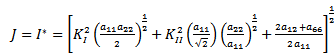
In this paper, fracture mechanics in orthotropic plates, stress and displacement distributions around the crack tip in an anisotropic material are considered. Classical displacement based finite elements, elements with penalized equilibrium and elements with drilling degrees of freedom are employed. The path independent integrals J and I* are applied to orthotropic fracture mechanics problems to determine the stress intensity factor at the crack tip. Again, convergence studies are done, and the path independence of J and I* are investigated for orthotropic problems. Numerical results for typical fracture specimens are presented and discussed. The effect of the degree of anisotropy and fiber orientation on the stress intensity factor is also demonstrated.
Keywords: Stress finite elements, Penalized equilibrium, Drilling degrees of freedom, Integrals J and I*, stress intensity factor
Cite this paper: A. Toubal , A. Sahli , S. Kebdani , O. Rahmani , Stress Intensity Solutions for Cracked Orthotropic Plates, International Journal of Mechanics and Applications, Vol. 3 No. 5, 2013, pp. 122-130. doi: 10.5923/j.mechanics.20130305.03.
Article Outline
1. Introduction
- Over the last decade or so, the finite element method has been firmly established as a standard numerical technique for solving fracture mechanics problems. It would have been impossible to solve non-linear fracture problems, without the employment of the finite element method[1].Rice's path-independent integral J is one of the most significant parameters in linear elastic fracture mechanics[1]. Recently the I* integral was introduced by Wu et al[1], which is the dual form of the J integral. The I* integral is based on the complementary energy principle of the system where the J integral is based on the strain energy density of the system. Path independent integrals (J/ I*) should be solved with finite elements that are based on the same energy principle as the path independent integrals to ensure path independence. It is due to this fact that the I*integral makes the assumed stress element (based on the complementary energy principle) play a powerful role in computational fracture mechanics. In the penalty-equilibrium approach, stress equilibrium is enforced in individual elements. Thus assumed stress elements with penalized equilibrium are ideal to solve the I* integral. In fracture mechanics, upper/lower bound estimation of the stress intensity factor becomes a matter of great significance as it is difficult to obtain the exact value of the stress intensity factor (K), no matter what experimental or numerical method is used due to the complexity of non-linear fracture[1]. It can be proved that the J integral forms an approximate lower bound to K when displacement based elements are used to solve the integral and that the I* integral forms an approximate upper bound to K when stress equilibrium elements are used.While assumed stress interpolation increases the accuracy of low order membrane elements, drilling degrees of freedom have an additional advantage in low order membrane elements. Above and beyond enrichment of the displacement field, it increases the accuracy of low order elements. Drilling degrees of freedom also increases the modeling capability of these elements.In recent years, composite materials have been used increasingly in various engineering disciplines, notably in the fields of aerospace and marine engineering.The crack tip singularity in orthotropic materials can be completely characterized in the same manner as in the isotopic case by properly defining anisotropic stress intensity factors[2]. Stress intensity factors are important parameters in the assessment of the fracture strength of anisotropic composite structural components. Within the framework of plane, linear elastic fracture mechanics, a problem of continuing interest is the calculation of the stress intensity factor in cracked orthotropic plates modeling fiber reinforced composites[3]. The study of the elastostatic fracture response of an orthotropic cracked plate subjected at infinity to a biaxial uniform load, and, the effects of orthotropy and load biaxiality on the near crack tip elastic fields is pointed out in[4]. The Kirchhoff and Mindlin plate theories are applied in this study to calculate the stresses and the energy release rates in delaminated orthotropic composite plates by[5]. With the growth in applications of composite materials, a problem of continuing interest is the calculation of the stress intensity factor in cracked orthotropic plates modeling fiber reinforced composites. The fracture of composite materials is an important and complex engineering problem. Significant defects can be built into a composite laminate during manufacturing of a new component. The material used can also be relatively fragile and large cracks can result from minor service mishaps. High performance composites often consist of high strength fibers in a weak matrix. Hence, crack formation and growth is constrained by the fiber direction, resulting in mixed mode crack deformation growth.Several numerical methods for determining stress intensity factors in cracked anisotropic plates have been developed by extending the methods originally developed for isotropic materials. The J integral can be used to develop a failure analysis approach which is applicable to both single and mixed mode crack problems in orthotropic materials. In a mixed mode, however, a simple application of the J integral does not provide sufficient information for a separate determination of mixed mode stress intensity factors. Various other methods are used to determine stress intensity factors for anisotropic materials: the Jk integral, the hybrid mongrel formulation, contour integrals based on Betti's reciprocal work theorem, etc.In this paper, the numerical evaluation of mode I and mode II stress intensity factors for orthotropic fracture mechanics problems is developed. The stress intensity factors are evaluated by using the finite element method, combine with path independent integrals
2. Anisotropic Stress and Displacement Field Near a Crack Tip
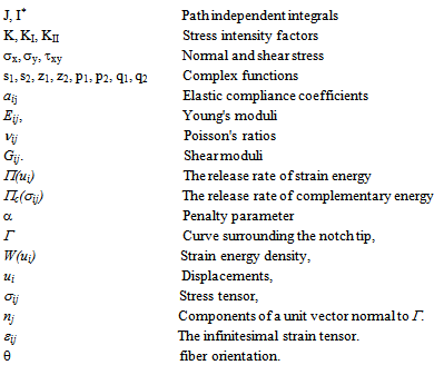
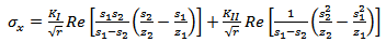
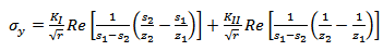
- The stress and displacement expressions in the neighborhood of the crack tip in homogeneous anisotropic media under a plane stress condition with zero body forces are given by Saxce and Kang[6] as:
 | (1) |
 | (2) |
 | (3) |
 | (4) |
 | (5) |
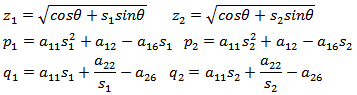 where Re denotes the real part of the complex function between brackets. s1, s2 and their conjugates are roots of the fourth order characteristic equation
 | (6) |
 | (7) |
3. Finite Element Formulation
- In recent times, elements with in-plane rotational (drilling) degrees of freedom have become quite popular. Apart from enrichment of the displacement field, which increases element accuracy, drilling degrees of freedom allow for the modeling of, for instance, folded plates and beam–slab intersections. These elements depend on a problem-dependent penalty parameter γ, which relates the in-plane translations to the in-plane rotations. Eventually, assumed stress formulations were combined with drilling degrees of freedom in a single element formulation, e.g. see Aminpour [7,8], Sze and Ghali[9], and Geyer and Groenwold for quadrilateral 8β and 9β drill families[10].Satisfaction of element equilibrium may relatively easily be enforced using a methodology similar to the post treatment or penalized equilibrium approach presented by Wu and Cheung[11]. For drill elements, penalized equilibrium was proposed by Groenwold et al.[12,13]. Penalized equilibrium depends on yet another problem dependent penalty parameter, which we indicate by α.Elements with drilling degrees of freedom and elements with assumed stress interpolations have the potential to improve the modeling capabilities of, in particular, low-order quadrilateral finite elements. Hence, it seems desirable to formulate low-order elements with both an assumed stress interpolation field and drilling degrees of freedom, on condition that the elements are rank sufficient and invariant.
4. The I* Integral
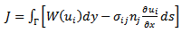
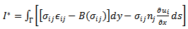
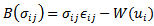
- Based on the energy foundation of the path-independent integral there must exist a dual version of Rice's J integral, which should also be a path-independent integral, be identical to J in value and be dependent on the system complementary energy. The I*integral presented by Wu et al.[14] is such an integral. The J integral is equivalent to the release rate of strain energy ∏(ui) with respect to the crack area, and the I* integral is equivalent to the release rate of the complementary energy ∏c(σij) with respect to the crack area. An interesting application of the I*integral is that it is able to provide the approximate upper bound solution for crack problems. Equilibrium based elements (based on the complementary energy principle) should be used to estimate the I*integral.For the purpose of developing the dual integral of J
 | (8) |
 | (9) |
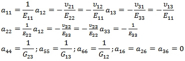
 , εij is the infinitesimal strain tensor.Formulating the constitutive relations of a linear elastic orthotropic material in global coordinates as follows:
 | (10) |
 | (11) |
5. Fracture Mechanics: Orthotropic Results
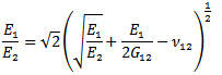
- To allow comparison with results presented in literature, the problems considered are mode I crack problems. For an orthotropic material crack problem to be a mode I problem, one of the principal axes of the material must be parallel to the crack axis. Therefore, only 0°, 90° or symmetric angle ply laminates can be considered. The fiber orientation in orthotropic material is defined as the angle between the crack axis and the fiber in a counterclockwise direction, see Fig 1.Three test problems are investigated, namely _ a center cracked panel (CCP) with 0° ply arrangement, uniformly loaded in tension (the reference solution is taken from[15]),_ a single edge cracked panel (SECP) with 0° ply arrangement, uniformly loaded in tension (the reference solution is taken from[15]), and a double edge cracked panel (DECP) with symmetric angle ply arrangements, uniformly loaded in tension (the reference solution is taken from[3] and[16]).The in-plane lines of material symmetry for the first two problems coincide with the x-y axis. The material constants are set to be E1 = 1, E2 = 10,β1 = 1 and β22= 0.1, where β1β2 = (E1/E2)1/2 and β1 + β2 = √2[(E1/E2)1/2 + E1/2G12- v12]1/2 [15]. The units of loading are consistent with that of E.
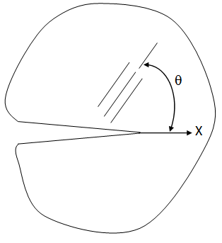 | Figure 1. Definition of the fiber orientation in an orthotropic material |
5.1. Convergence Study
- To study the influence of mesh refinement on the prediction of the stress intensity factor in orthotropic materials, a convergence study is firstly done. For the convergence study the center cracked panel with 0° ply arrangement is considered. Three different meshes are used with the same 5 integration contours.Mesh 1 consists of 17x9 elements in total and a radial fan of element around the crack tip of 7x3 elements. Mesh 2 is a bisection of Mesh 1, and Mesh 3, in turn, is a bisection of Mesh 2.For the convergence study we consider the following elements:_ J integral: Q4 (A displacement based quadrilateral element)_ J integral: Q4X (A displacement based quadrilateral element with drilling degrees of freedom)_ I* integral: PS(α) (A penalized version of the assumed stress quadrilateral element proposed by Pian and Sumihara[17])_ I* integral: 8β(α) (A penalized version of the assumed stress quadrilateral element with drilling degrees of freedom and 8 β parameters)_ I* integral: 9β(α) (A penalized version of the assumed stress quadrilateral element with drilling degrees of freedom and 9 β parameters)For the meshes considered, the stress intensity factor K1 calculated using the Q4 element violates the bound theorem, (see Fig 2(a)), and the results reveal a notable path dependency. This is due to the material orthotropy, which requires a very fine mesh for the Q4 elements[15].With Q4X elements, the J integral is path-independent and satisfies the bound theorem (see Fig 2(b)). As expected, the stress intensity factors calculated with the J integral and Q4X form a lower bound to the true value of the stress intensity factor, but the calculated stress intensity factor does converge to the analytical value with mesh refinement. When evaluating the J integral for orthotropic materials, the Q4X element seems superior to the Q4 element.We now turn the attention to the assumed stress based elements: For PS(α), 8β(α) and 9β(α), a convergence study is presented in Figs 3(a), 3(b) and 3(c). The results confirm the path independence of the elements, while an upper bound to the stress intensity factor is predicted, as may be expected. Again, the calculated stress intensity factors do converge to the analytical solutions with mesh refinement. Clearly, the results obtained with mesh 3 are superior to the results obtained using mesh 1 or mesh 2.
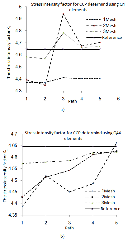 | Figure 2. Convergence study of KI for the orthotropic CCP with different displacement based elements: (a) Q4 (b) Q4X |
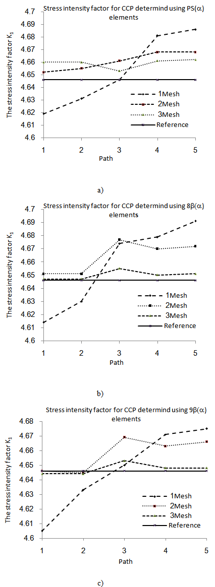 | Figure 3. Convergence study of KI for the orthotropic CCP with different assumed stress elements:(a) PS(α) (b) 8β(α) (c) 9β(α) |
5.2. Selected Results Demonstrating Path Independence
- General results for the problems of interest are now presented. Throughout, mesh 3 is used.Center cracked panel with a 0° ply arrangementFig. 4: The reference solution is K1 = 4.646. The results demonstrate adherence to the bound theorems: The stress intensity factor determined with the I* integral using penalized equilibrium elements forms an upper bound to the KI factor, while the stress intensity factor determined with the J integral and Q4X elements forms a lower bound to KI.Single edge crack panel with 0°ply arrangementFig. 5: Unfortunately, no theoretical reference solution could be found for this problem, but the results compare well with those obtained by Xiao et al[15].
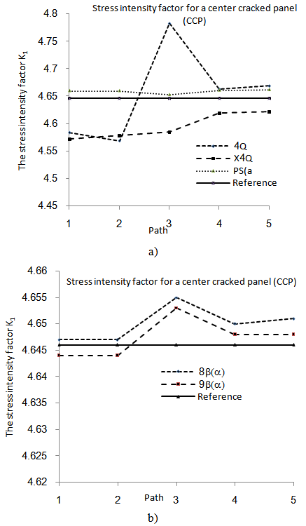 | Figure 4. Summary of results for an orthotropic center cracked panel with θ= 0°fiber angle: (a) Q4, Q4X and PS(α) elements (b) 8β(α) and 9β(α) elements |
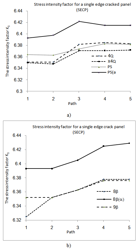 | Figure 5. Summary of results for an orthotropic single edge cracked panel with θ = 0° fiber angle: (a) SECP with θ = 0° Q4, Q4X, PS and PS(α) elements (b) SECP with θ = 0° 8β, 8β(α) and 9β elements |
5.3. The Effect of Fiber Orientation on the Stress Intensity Factor
- The effect of fiber orientation on a double edge cracked panel with a symmetric ply arrangement is now studied. Symmetric fiber orientations of ±0°, ±10°, ±20° ... ±90° are considered.The calculated stress intensity factors for this problem are shown in Fig 6. The results are compared with the results obtained by[16] and[3] where possible. For the double edge cracked plate problem, the material constants used are:_ E1 = 144.798 GPa, E2 = 11.722 GPa, G12 = 9.6532 GPa, and ν = 0.21.The double edge cracked plate dimensions used are:_ Crack length: a = 3.5, Width: 2b = 14, Height: 2c = 14,The units of loading are consistent with that of E.For the double edge cracked panel, the results are summarized in Figs 6(a) and 6(b). The results reveal a slight (unimportant) path dependence.The results obtained for the DECP with symmetric angle ply lamina are shown in Fig 7, compare very well with the results obtained by Chu and Hong[16]. Comparing the results obtained by Chu and Hong with the results obtained by Kim[3], it is noted that large discrepancies exist between these results, which peak around angles of ±60s. According to Chu and Hong[16] it seems that these discrepancies are due to Kim's[3] miscalculation of compliance coefficients.The agreement with the results presented by Chu and Hong seems to indicate that the current implementation is correct.
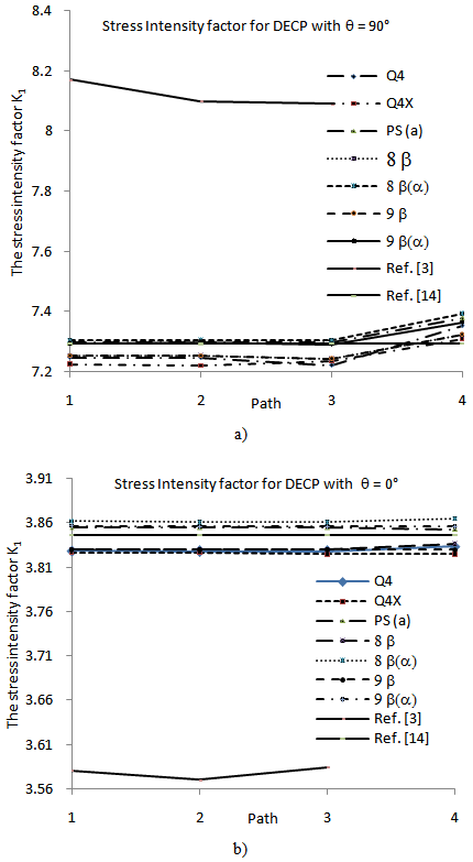 | Figure 6. Summary of results for an orthotropic double edge cracked panel: (a) fiber angle θ= 90° (b) fiber angle θ= 0° |
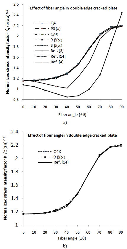 | Figure 7. Results for the effect of fiber orientation on a double edge crack plate, θ= ±0°through θ= ±90°(a) Solution for all elements (b) Solution for Q4X and 9βαonly |
5.4. The Effect of the Degree of Anisotropy on K
- To consider the effect of the degree of anisotropy on the stress intensity factor, a center cracked plate under uniform tensile stress is now considered. This problem was also considered by Su and Sun[18]. The ratio E1/E2is varied to determine the influence of the degree of anisotropy on the stress intensity factor. The height to width ratio h/w and the crack length to width ratio a/w are varied to estimate the effect of geometry on the stress intensity factor. Height to width ratios of h/w = 1.0, 1.5, and 2.0 are considered.The material properties used are:_ Young's modulus E1 = 30.0, and_ Poisson's ratio ν12= 0.3.The values of E2 and G12 are obtained from
 The results are summarized in Figs 8 and 9. When comparing the results with those obtained by Su and Sun[18], it is noted that the correlation between the results is very high.
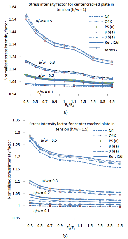 | Figure 8. The effect of the degree of anisotropy and height to width ratio for the orthotropic CCP with 0° ply arrangement: (a) Height to width ratio h/w = 1 (b) Height to width ratio h/w = 1.5 |
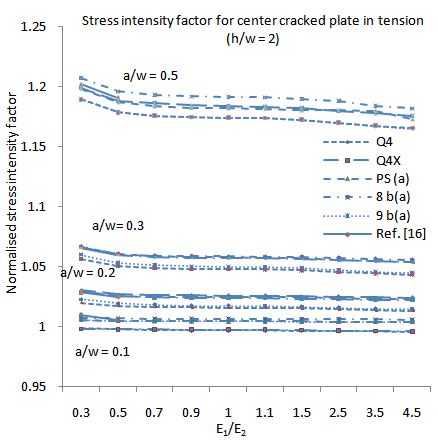 | Figure 9. The effect of the degree of anisotropy and height to width ratio for the orthotropic CCP with 0°ply arrangement: Height to width ratio h/w = 2 |
6. Conclusions
- It is well known that orthotropic fracture mechanics problems can effectively be solved by combining the finite element method and the path independent integrals J and I*.Not as well known, is that assumed stress finite elements, combined with the I* integral, can be used to predict an upper bound to the stress intensity factor. Assumed stress elements without penalized equilibrium tend to under predict the stress intensity factor if the mesh is not highly refined; to predict the upper bound, assumed stress elements with penalized equilibrium are an attractive modeling option.Solving the J integral with displacement based elements, yields a lower bound to the stress intensity factor. A lower bound in isotropic fracture mechanics problems can be predicted accurately with Q4 or Q4X elements. In orthotropic fracture problems however, Q4 elements reveal a notable path dependency, for such problems, elements with drilling degrees of freedom represent a superior modeling option to Q4 elements.When using elements with drilling degrees of freedom to solve fracture mechanics problems, the integration scheme used and the value of the penalty parameter γin the elements, needs consideration. Reduced integration, with a small center point weight, or a too large penalty parameter, can introduce a checkerboard like locking pattern. Both the integration scheme and the penalty parameter γinfluence the stability of elements with drilling degrees of freedomFrom a mechanics of material point of view, it is shown that the degree of anisotropy and the fiber orientation in orthotropic fracture mechanics problems have a large influence on the stress intensity factor. The influence of the degree of anisotropy decreases as the ratio of E1/E2 increases. When the degree of anisotropy is larger than 1, the stress intensity factor is only influenced significantly for large a/w and small h/w ratios.
7. Recommendations for Further Studies
- _ In the section on displacement based elements with penalized equilibrium we only considered regular geometries; a treatment for irregular (generally distorted geometries) is awaiting.This can probably be done using1. Analytical or symbolic techniques to _nd the characteristic polynomial, or2. Through approximate relationships derived from the mapping to a `regular' parent element._ While approximate relationships exist which relate the size of the plastic zone to a material specific stress intensity value, it is not clear what the true value of rotations in the plastic zone are. It is recommended that this is addressed in a future study._ A further study on the effect of fiber orientation on the stress intensity factor in orthotropic materials is recommended._ The use of elements with drilling degrees of freedom in more complicated fracture mechanics problems will be a interesting study._ A further study using path independent integrals (e.g. Jk) that can split the mixed mode stress intensity factor into Mode I and Mode II stress intensity factors is recommended.
Nomenclature