André Luís Cerávolo de Carvalho1, Marcos Estevão Assumpção1, Diego Amorim Caetano de Souza2, Francisco Antonio Rocco Lahr2, André Luis Christoforo1
1Department of Mechanical Engineering, Federal University of São João del-Rei, São João del-Rei, 36307-352, Brazil
2Department of Structural Engineering, Engineering School of São Carlos (EESC/USP), São Carlos, 13566-590, Brazil
Correspondence to: André Luis Christoforo, Department of Mechanical Engineering, Federal University of São João del-Rei, São João del-Rei, 36307-352, Brazil.
| Email: |  |
Copyright © 2012 Scientific & Academic Publishing. All Rights Reserved.
Abstract
Brazil Society of Automotive Engineers (SAE Aerodesign Competition) proposes to engineering, physical sciences and aviation design student the challenge of construct an Unmanned Aerial Vehicle (UAV). In addition, this event aims to promote the exchange and dissemination of aeronautical engineering techniques and knowledge. Among them, there is simulation softwares based on finite element method. This study presents the mesh influence in the mechanical analysis performance with contact for a radio controlled aircraft wheel. For this study, were used the aircraft TKV 2011 wheel made with Aluminum 7075-T651, with mechanical properties were obtained by AlumiCopper® manufacturer. The linear static analysis results were compared with number’s variation of mesh elements. The mesh refinement, which requires a large computational effort and time required to perform the calculations, becomes unfeasible when the maximum size of the edge element is less than 0.25 mm, result in proximal values.
Keywords:
Finite Element Method, Mesh, Structural Components
Cite this paper: André Luís Cerávolo de Carvalho, Marcos Estevão Assumpção, Diego Amorim Caetano de Souza, Francisco Antonio Rocco Lahr, André Luis Christoforo, Finite Element Method Used in the Mechanical Analysis of a Wheel for a Radio Controlled Aircraft Project, International Journal of Mechanics and Applications, Vol. 3 No. 5, 2013, pp. 117-121. doi: 10.5923/j.mechanics.20130305.02.
1. Introduction
The SAE Aerodesign event happens yearly in São José dos Campos, aiming the competition between small aircrafts built by teams formed by graduation students from the engineering courses of the main Brazilian and outside universities. The aircraft must present high structural efficiency and carry the maximum of charge that it is able to, answering the design requests of the competition.The teams are divided in three project classes: regular, open and micro. The competition is divided in two distinct steps to the evaluation of the aircraft’s design and performance. Among the main requests analyzed on the design step are: aerodynamic, stability and control, structural analysis and performance. The second step consists on the competition, in which the aircraft is tested in successive attempts, transporting useful charges that are always rising, until the limit conditions of each project.The competitiveness between teams stimulates the study of light subjects with satisfactory mechanical properties to the development of lighter aircrafts and with bigger charge capacity.It is important to study of structural components like Landing Train, Triquilha and Wheel because they are elements of the aircraft that go through constant modifications depending the project’s requests and efforts. Among the components, the wheel is highlighted because it is the element that makes the connection between the aircraft and the ground. Designed to withstand small displacements and strains without losing its characteristics, it is an element in which simulation softwares studies using the Finite Element Method (FEM) are present and important to a better component design.The use of numerical simulation softwares becomes a tool for obtaining results of stresses and displacements of structural components without the immediate need for a prototype for future analysis and corrections, reducing time and expense.This paper presents the mesh refinement influence via FEM in the mechanical analyses of TKV wheel aircraft at 2011 SAE competition, making it possible to investigate the mesh influence in the stresses and strains results.
2. Material and Methods
2.1. Methodology for Design
Aiming to better understand the behavior of the stresses in the structure of the wheel, the same is subject to numerical studies by the team in order to better measure its shape, resulting in the reduction of its weight. As shown in Figures 1 and 2.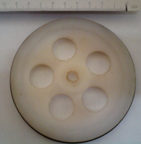 | Figure 1. Wheel TKV 2009, nylon material |
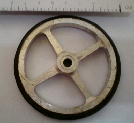 | Figure 2. Wheel TKV 2010, aluminum material. |
There was a great evolution over the years about the design and the material used for its manufacture. The application of MEF (Finite Element Method) allows for the wheel’s design to be possible to determine the minimum size of mass relief, the best format for the section of the rays, Figure 3, where the size of the cube are placed bearings and mode of intersection of the ray with the oaring runway (used with tire wheel).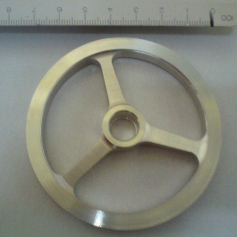 | Figure 3. Wheel TKV 2011, aluminum material |
To determine the configuration of the aircraft, the type of wheel’s choice is one of the premises of the project. The fixed tricycle configuration has as an advantage the facility of Assumption landing.In order to understand what the requests are and then what is expected of a wheel, it is necessary to study the loads acting on this component.Calculations of the applied loads were made to three different landing situations: landing on three wheels, landing on two wheels and landing on one wheel[1]. From these situations, landing on two wheels is considered a normal landing situation, being the most critical condition when it occurs only by a wheel. From the linear static calculations[2] resulting in 480.89 N (456.2 N normal to the surface of the component and 152.1 tangential thereto), the wheels are sized (Figure 4) from the critical landing condition (Figure 5). The boundary conditions to be adopted in the model were designed according to limitations imposed by the aircraft wheel assembly as well as the load presented.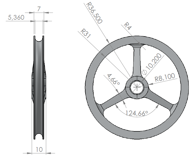 | Figure 4. Wheel TKV 2011, aluminum material |
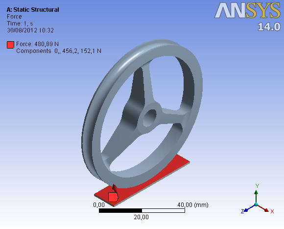 | Figure 5. Wheel TKV 2011, Critical landing condition, 480,89N |
2.2. Finite Element Method
The Finite Element Method (FEM) shows up as an excellent calculation tool used to analyze the behavior of materials used in structural projects, as well as to evaluate the mechanical performance of these structures.Historically, the FEM emerged in 1955 as an evolution of the matrix analysis of cross-linked models, motivated by the advent of the computer and elaborated in order to design structures of continuous models.The FEM can be considered as a technique of generating approximation functions, which can be used to interpolate displacements, strains, stresses and strains over the area of the element.To approximate the resolution of structural problems according to the FEM, the shape functions can be applied directly to your differential equation (Weighted Residuals Method) or the energetic principles such as the principle of virtual work (PVW).The displacement in structural problems is taken as unknown key, obtained by means of solving a system of equations[3-17], as expressed in Equation 1, and its construction is due to the provision of the mesh, the nodes of finite element in the structure, as seen in Figure 6.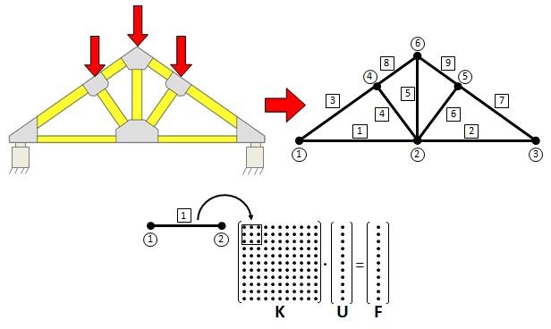 | Figure 6. Example of discretization of a finite element mesh on a trellis |
 | (1) |
In which:[K] - stiffness matrix of the structure; {U} - vector of nodal displacements of the structure;{F} - equivalent nodal force vector of structure.In this paper, the mechanical performance verification of the Wheel is done with the aid of the software Ansys®, developed with the FEM fundamentals. The element MESH200[18] was used to compose the mesh of the finite elements model. This element has tetrahedral geometry, with quadratic approximation, composed by ten nodes, containing three degrees of freedom per node (translation in three dimensions), showing in Figure 7. The tetrahedral mesh was adopted in function that yours easy adaptation to geometries and for the good answer to corner angles, however, as a consequence, there is a considerable increase in computational cost[11]. This "cost" is certainly rewarded for agility in obtaining the mesh, accuracy and reliability offered by the element.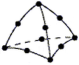 | Figure 7. Tetrahedral finite element type |
2.3. Numeric Rating
The material used for the component is aluminum 7075 T651, supplied by AlumiCopper®, with yield strength of 505 MPa and ultimate tensile strength of 572 MPa[19]. The properties provided by the manufacturer are shown in Table 1.| Table 1. Aluminium 7075 T651 properties |
| | Specific Weight (g/cm³) | Elasticity Modulus(Mpa) | Rigidity Modulus(Mpa) | Melting Temperature(°C) | | 2,8 | 73000 | 27500 | 475-630 | | Specific Heat (0-100°C)(Cal./g°C) | Linear Expansion Coefficient(L/°C) | Thermal Conductivity (25°C) (Cal./cm °C) | Electric Conductivity (IACS)% | | 0,23 | 24x10-6 | 0,29 | 30 |
|
|
A study of the mesh influence through the size of the elements in the model was proposed, using a model in FEM to best represents the extreme condition imposed on the component that occurs at the moment of landing. Were investigating the number of elements for the convergence of stress and displacement.The maximum Von-Mises stress criterion was used to analyze the results for being based on Mises-Hencky theory, also known as shear energy theory or theories of maximum distortion. The theory says that a malleable material begins to yield at a site where the Von-Mises stress becomes equal to the threshold stress. In most cases, the yield point is used as threshold stress[20], the same being used for the calculation and wheel TKV 2011 sizing.The model consists to analyze the component at the time of landing. Clamped on the shaft resulting in a load (480.89 N) application to the surface of the component through the contact (Figure 8).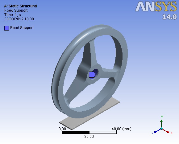 | Figure 8. Wheel TKV 2011, collet shaft |
The area of load application was defined where the influence of rays is less present in the analysis of stress and strain, in other words, in the worst condition where the wheel is requested. The boundary conditions adopted in the finite element model devised according to the constraints imposed by the aircraft wheel assembly as well as the load presented.
3. Results
The mesh used has a maximum dimension of 4 mm edge, having refinement of the elements up to 0.1 mm of edge, as illustrated in Figures 9 and 10.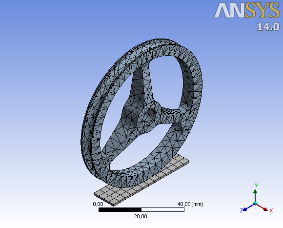 | Figure 9. Mesh of the component: maximum element size of 4mm |
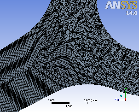 | Figure 10. Refined mesh: maximum element size of 0.1 mm, expanded in the clamped region |
Thirty-two simulations were made, 16 simulations to verify the maximum size of the edge of the element in 4mm; 3,5mm; 3mm; 2,5mm; 2mm; 1,5mm; 1mm; 0,5mm; 0,45mm; 0,4mm; 0,35mm; 0,3mm; 0,25mm; 0,2mm; 0,15mm; 0,1mm; only in the studied component keeping the second component with a fixed element size of 4mm of edge, and 16 another simulations with the same conditions, however, used in the two components.Figure 11 and 12 represent the evolution of variables "Strain" and "maximum Von-Mises stress" versus the number of mesh elements, whose component studied variation is represented by blue color and two components variation is represented by red color.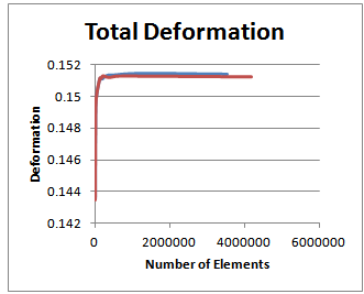 | Figure 11. Total Deformation |
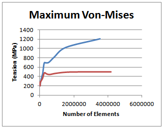 | Figure 12. Stress (MPa) |
For the number of elements of approximately 550000, corresponding to mesh element with a maximum length of 0.25 mm edge, the convergence has been achieved in the results of deformation. However, the maximum stress results presented convergence only in the analysis with variation in the size of the element in the two components.
4. Conclusions
From the results of stresses and strains from the FEM simulations, it’s possible to conclude that the size of the upper element to the maximum edge of 0.25 mm are results with a large variations, not allowing a sizing component with consistency. With the size of the maximum element edge less than 0.25 mm in both components, the results converge near to, allowing greater reliability in FEM model for the design of the component.Thus, the mesh refinement, which requires a large computational effort and time required to perform the calculations, becomes unfeasible when the maximum size of the edge of the element is less than 0.25 mm, because the results are very proximal.
References
| [1] | Oliveira, P. H. I. A. Introdução às Cargas nas Aeronaves. Centro de Estudos Aeronáuticos da Escola de Engenharia da Universidade Federal de Minas Gerais. www.demec.ufmg.br/cea. Belo Horizonte, 2008. |
| [2] | Hibbeler, R. C. Estática: Mecânica para Engenharia, 10ª Edição, Editora, Prentice Hall, Rio de Janeiro BR, 542 p., 2005. |
| [3] | Coda, H. B.; Paccola, R. R.; Sampaio, M. S. M. Fully adherent fiber matrix FEM formulation for geometrically nonlinear 2D solid analysis. Finite Elements in Analysis and Design, v. 66, p. 12-25, 2013. |
| [4] | Coda, H. B.; Paccola, R. R. A FEM procedure based on positions and unconstrained vectors applied to non-linear dynamic of 3D frames. Finite Elements in Analysis and Design, v. 47, p. 319-333, 2011. |
| [5] | Carrazedo, R.; Coda, H. B. Alternative positional FEM applied to thermomechanical impact of truss structures. Finite Elements in Analysis and Design, v. 46, p. 1008-1016, 2010. |
| [6] | Paiva, J. B.; Almeida, V. S. A mixed BEM-FEM formulation for layered soil-superstruture interaction. Engineering Analysis with Boundary Elements, Inglaterra, v. 28, p. 1111-1121, 2004. |
| [7] | Mendonça, A. V.; Paiva, J. B. An elastostatic FEM/BEM analysis of vertically loaded raft and piled raft foundation. Engineering Analysis with Boundary Elements, Inglaterra, v. 27, p. 919-933, 2003. |
| [8] | Piedade N., D.; Ferreira, M. D. C.; Proença, S. P. An Object-Oriented class design for the Generalized Finite Element Method programming. Latin American Journal of Solids and Structures, v. 10, p. 1267, 2013. |
| [9] | Góis, W.; Proenca, S. P. B. Generalized Finite Element Method on non-convential Hybrid-Mixed formulation. International Journal of Computational Methods, v. 9, p. 1250038-1, 2012. |
| [10] | Nunes, C. C.; Soriano, H. L.; Venancio F. F. Geometric Non-linear Analysis of Space Frame with Rotation Greater than 90, with Euler Angles and Quasi-fixed Local Axes Suystem. International Journal of Non-Linear Mechanics, United States, v. 23, p. 1195-1204, 2003. |
| [11] | Wang E., Nelson T., Rauch R. Back to Elements - Tetrahedra vs. Hexahedra, 2004 International ANSYS Conference Proceedings, Pittsburgh, 2004. |
| [12] | Alvarenga, R. C. S. S.; Antunes, H. M. C. C. Otimização de treliças. In: Congresso Ibero Latino-Americano Sobre Métodos Computacionais para Engenharia, 15, Belo Horizonte, MG. Anais, pp 1699-1708, 1994. |
| [13] | Cheung, A. B.; Lindquist, M.; Calil, C. J. Calibração de propriedades elásticas de uma placa ortótropa utilizando algoritmos genéticos. In: Revista Sul-americana de Engenharia Estrutural. Universidade de Passo Fundo. Mato Grosso do Sul. Vol.1, nº 2, pp74-92, 2004. |
| [14] | Christoforo, A. L. Influência das irregularidades da forma em peças de madeira na determinação do módulo de elasticidade longitudinal, Tese de Doutorado, EESC – USP, 2007. |
| [15] | Góes, J. L. N. Modelos teóricos para o dimensionamento de pontes com tabuleiro multicelular de madeira protendida. In: XXXI Jornadas Sud-americanas de Ingeniería Estructural. Facultad de Ingeniería. Universidad Nacional de Cuyo. Mendonça. Argentina. Anais, CD-ROM, 2004. |
| [16] | Mascia, N. T. Considerações a respeito da anisotropia da madeira. Tese (Doutorado) – Escola de Engenharia de São Carlos, Universidade de São Paulo. São Carlos, SP, 1991. |
| [17] | Rigo, E. Métodos de otimização aplicados à análise de estruturas. Dissertação (Mestrado) – Escola de Engenharia de São Carlos, Universidade de São Paulo. São Carlos, SP, 1999. |
| [18] | Assumpção, M. E.; Nacif, G. L. ; Panzera, T. H. ; Chritoforo, A. L. Projeto Estrutural de um Trem de Pouso para uma Aeronave Rádio-Controlada. In: 9º Simpósio de Mecânica Computacional, 2010, São João del Rei. 2010. |
| [19] | Callister, Jr, W. D. Ciência e Engenharia de Materiais Uma Introdução, 7ª Edição, Editora, LTC, Rio de Janeiro BR, 705 p., 2008. |
| [20] | Hibbeler, R. C. Resistência dos Materiais, 7ª Edição, Editora, Pearson Education, Rio de Janeiro BR, 688 p., 2010. |
 Abstract
 Reference
 Full-Text PDF
 Full-text HTML