Shengyong Zhang
College of Engineering and Technology, Purdue University North Central, Westville Indiana, 46391, USA
Correspondence to: Shengyong Zhang, College of Engineering and Technology, Purdue University North Central, Westville Indiana, 46391, USA.
| Email: |  |
Copyright © 2012 Scientific & Academic Publishing. All Rights Reserved.
Abstract
One way of designing lightweight vehicles is to utilize more thin-walled steel components with properly designed reinforcements. Local architecture changes, particularly if the changes are made at optimal locations, can decrease the nonuniformity of the internal load/strain energy distribution and thus lessen the need for low density material substitutions. Gauge sensitivity methodologies are a family of techniques for assessing the effect of thickness changes on automotive structural performance parameters. They may be applied to support design optimization decisions at the level of the entire body-in-white, body components and specific points. This paper defines local level gauge sensitivity based on the concept of strain energy density. The changes in the structural parameters are computed with respect to thickness changes at specific points in the body continuum. Application studies, including visual rendering of the local gauge sensitivity data, are illustrated by a series of example cases for reinforcing a light-duty truck cab.
Keywords:
Gauge Sensitivity, Vehicle Body-in-White, Stiffness, Weight Reduction
Cite this paper: Shengyong Zhang, Improving Vehicle Body Stiffness with Reinforcements at Optimal Locations Based Upon Local Gauge Sensitivity, International Journal of Mechanics and Applications, Vol. 3 No. 4, 2013, pp. 81-87. doi: 10.5923/j.mechanics.20130304.04.
1. Introduction
A significant amount of research into automobile body-in-white (BIW) structures has been motivated by a desire to improve fuel efficiency and reduce gas emissions. The need to achieve this objective has been driven by automobile fuel efficiency and emission policies and consumer demands. One of the most direct approaches is to reduce BIW weight. Lightweight BIW leads to a secondary weight reduction in other subsystems (the chassis, for example), which in turn requires less energy for traction. There are three opportunities for reducing BIW weight: alternative material substitutions, innovative manufacturing technologies, and architecture optimization.Substituting high density steel with light materials has been a subject of research for weight reduction in the last decades. The key characteristics of aluminium, including high strength to weight ratio, corrosion resistance and thermal conductivity, make it the most common candidate for substitution[1]. Currently, the usage of aluminium in automobiles increases mainly as castings in transmissions, engine blocks, and wheels. Material cost and manufacturing cost, however, still restrict the replacement of aluminium for steel in automobile bodies for high volume production [2]. Magnesium is about 35 percent lighter than aluminium and over four times lighter than steel. Magnesium alloys are being suggested for some components traditionally fabricated from steel for additional weight reductions[3]. In addition to lightweight nonferrous alloys, thermoplastics and composites are also considered. If increased fuel economy alone is considered, however, the additional cost associated with material substitution for BIW may be more efficiently expended on powertrain enhancement, unless the material prices are significantly decreased and the fabrication technologies are well developed.Steel still remains the most cost-effective material for manufacturing vehicle bodies despite attempts to find efficient alternative materials. This conclusion is based upon the low commodity cost of sheet steel, broad industry manufacturing experience with steel, the ease of separating steel from the waste stream (promoting recyclability) and steel’s structural properties. The most direct way to reduce the weight of steel vehicle bodies is to reduce the thickness of the panels used for the majority of the body structures. Modern vehicle designs are usually stiffness-constrained and such thickness decreases will lower the structural stiffness unless the body architecture is also modified to achieve supplemental stiffening. It is well known that localized compliance in body subassemblies such as major body joints, pillars, and rails, plays crucial roles in determining the overall body stiffness. Local architecture changes, particularly if the changes are made at optimal locations, will decrease the nonuniformity of the internal load/strain energy distribution, and thus result in optimal designed architectures and lessen the need for low density material substitutions.Architecture optimization has long been an important topic in automotive research for enhancing sheet metal structures. Reference[4] studies the reinforcements of an idealized T-shaped joint. It is concluded that properly designed reinforcements of a complex part, such as an automobile major body joint, can reduce stress concentrations and accordingly lessen or even eliminate the weight advantage that aluminum holds over steel. Reference [5] reinforces one of the hinge pillar-rocker joints of a light truck cab with a simple stiffening bulkhead. This change is minor relative to the extent of the entire cab structure, but results in a significant potential weight saving. Reference[6] applies CAE-based optimization by taking the thickness of body panels as design variables to increase the dynamic stiffness of an automobile body. An optimization algorithm is developed to reinforce body panels for improved performance. Reference[7] conducts shape optimization to an automobile body for increasing bending and torsional stiffness based on the thickness sensitivity results. Reference[8] investigates the modal mobility performance of a light van BIW structure. The effect of adding stringers to the roof and side panels is studied for eliminating some of the local panel modes, and thus improving the structural performance. Gauge sensitivity methodologies are a family of techniques for assessing the effect of thickness changes on automotive structural performance parameters. They may be applied to support design optimization decisions at the global level (e.g., an entire passenger car body), component level (e.g., B pillar to rocker joint) and local level (e.g., a critical point on a rocker). Global level and component level gauge sensitivity has been developed with the use of extensive structural parameters, such as stiffness and natural frequency[4],[5]. They allow quantitative consideration of the tradeoffs between weight reduction and structural performance resulting from design modifications involving material substitution or same material re-gauging. Development of local gauge sensitivity method requires the use of intensive structural parameters. Strain energy density and von Mises stress, for example, are two candidate field variables[5],[9].This paper computes local gauge sensitivity based on the concept of strain energy density. The changes in the structural parameters are computed with respect to thickness changes at specific points in the body continuum. Application studies, including visual rendering of the local gauge sensitivity data, are illustrated by a series of example cases for reinforcing a light-duty truck cab.
2. Local Gauge Sensitivity and its Effect on the Structural Performance
Defining a gauge sensitivity function that can characterize the response of individual points to thickness changes requires selection of an intensive variable. Reference[9] calculates the micro-lambda by comparing the von Mises stresses in the original thin-walled shell structure with those in the same structure but with thickness doubled. Strain energy density, defined as the strain energy per unit volume, is an intensive variable that is inversely proportional to stiffness. Strain energy density can be interpreted as a tensor, much like a stress field (von Mises stress, for example, includes only the distortion portion of the strain energy), suggesting that the reciprocal of the strain energy density at a point be used as the basis for determining local gauge sensitivity. The fundamental definition of gauge sensitivity then yields the following expression for local gauge sensitivity at an arbitrary point, j[5].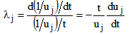 | (1) |
In finite element notation, the equation becomes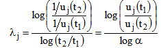 | (2) |
Here uj(t1) and uj(t2) are the strain energy stored in the jth element corresponding to the two known values of thickness t1 and t2, respectively. α is defined as gauge modification factor, such that α = t2/t1. λj is referred to as gauge sensitivity of the jth element.Reference[10] conducts a strain gage–based experimental study on local gauge sensitivity. Four thin-walled beam specimens were fabricated. The beams have a closed “hat” section similar to those bending-loaded components found in the vehicle body structure. While geometrically similar, the specimens have different wall thicknesses, representing the gauge modifications that might be considered during an architecture optimization exercise. Eight strain gauge rosettes are installed on each specimen that allows the state of strain at critical points to be characterized. Each specimen is mounted in a test fixture at one end while the other end is transversely loaded with a dead weight. The rosettes yield strain values, which result in strain energy density values, which in turn result in local gage sensitivity estimates. The measured data are compared to the FEA-based data and they are in good agreement.Stiffness is crucial for designing automobile BIW structure. Stiffer is generally considered to be better. Prediction based on the local gauge sensitivity yields the stiffness changes due to local gauge modification. The results will assist gauge optimization of automobile BIW architecture in stiffness-driven design. The following derivation is based on strain energy because strain energy minimization is equivalent to maximizing the overall stiffness.In finite element notation, the total strain energy of a loaded structure, U, is evaluated by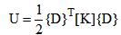 | (3) |
where[K] is the global stiffness matrix and {D} the nodal displacement vector. The static equilibrium equation is | (4) |
It is assumed that the external force vector {F} is independent of element thickness. Differentiating Eq. (4) with respect to the thickness of the jth element, tj, and substituting the result in Eq. (3), one can express the sensitivity of the total strain energy to thickness as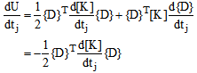 | (5) |
The differentiation of[K]with respect to tj gives non-trivial coefficients only if these coefficients are contained in the stiffness matrix of element j. In other words, all coefficients which are independent of element j will become zero after differentiation. Non-related coefficients in vector {D} can be eliminated accordingly and the global nodal displacement vector can be replaced by the nodal displacement vector of element j.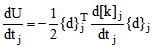 | (6) |
where {d}j and[k]j are the nodal displacement vector and stiffness matrix of the jth element, respectively. It is convenient to express this equation in the discrete form as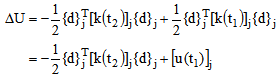 | (7) |
Here ΔU represents the change in the total strain energy due to the change in the thickness of the jth element.[u(t1)]j is the strain energy stored in the jth element at the original thickness t1.[k(t2)]j and[k(t1)]j are the stiffness matrixes of the same element before and after gauge modification, and are related through λj by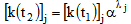 | (8) |
Substituting Eq. (8) in Eq. (7) gives the approximation of the total strain energy due to thickness change in the jth element from t1 to t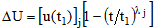 | (9) |
A thin-walled beam with hat cross section is adopted as an example for validating the results of local gauge sensitivity analysis. A finite element model is developed for this beam, see Figure 1. The beam is fixed at one end while an external force applied transversely at the other end through a rigid bar. A series of finite element analyses (FEA) are conducted to calculate the changes in the total strain energy of the beam due to changes in the thickness of each shell element individually. The finite element results are used as baselines in this example for comparison with the results of the following gauge sensitivity analysis.Of course, use of Eq. (9) requires a value of gauge sensitivity for each shell element. The gauge sensitivity value can be calculated by comparing the element strain energy corresponding to two known values of thickness based on Eq. (2). With gauge sensitivity value determined for each element, one can predict the changes in the total strain energy of the beam due to specified thickness changes by using Eq. (9). The gauge sensitivity results are shown in Figure 2 and it is clear that they are in good agreement to the FEA-derived values.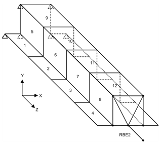 | Figure 1. Thin-walled beam with hat cross section under cantilever loading |
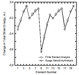 | Figure 2. Changes in the total strain energy of the thin-walled beam due to thickness increasing in each element individually |
To support collaborative assessment of the total strain energy change due to thickness change in each element, FEA ASCII output files are used to calculate the local gauge sensitivity data and display the resulting plots in Altair Hyperworks. Translators in Hyperworks are referred to as the utilities that convert various types of result files into a format that HyperGraph can read. Hyperworks supplies several result translators such as hmnast, hmansys, etc. Hmnast, for example, can be used to translate MSC Nastran analysis result files to Hyperworks binary result files. These Hyperworks binary result files can in turn be plotted by Hyperworks post-processing. To plot a user-defined variable, however, one needs to design a special result translator. By using C library in Hyperworks (hmlib, hmreslib, hmmodlib, etc.), a customized translator has been programmed for visual rendering of the gauge sensitivity data.The distribution of strain energy changes based on Eq. (9) is much like a stress or strain field. One can use this distribution in a manner analogous to the way a designer uses a stress distribution to identify critical points or optimization opportunities. However, the interpretation of the strain energy change field is fundamentally different in that it identifies locations in a structure that are excessively prone to elastic instability[5]. Regions with high values are interpreted as good locations for stiffening withincreased-gauge panels, bulkheads, seam welds or bonding.Thin-walled structures are more efficient than thick-walled structures, provided the effect of elastic instability associated with the onset of bucking can be mitigated. Reference[11] studies the influence of elastic instability on stiffness–based gauge sensitivity and demonstrates that as gauge reduction proceeds, the onset of elastic instability results in instantaneous increase in gauge sensitivity. It is concluded that thin, elastically stable structures without stress concentrations have inherently low gauge sensitivity values and correspondingly high material effectiveness.
3. Application Studies: Efficient Architecture Enhancements at Optimal Locations
3.1. B Pillar to Rocker Joint
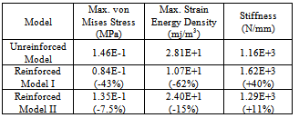
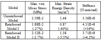
A major body joint of an automobile BIW is traditionally defined as the structure formed by the intersection of two or more beam-like members. Major body joints are compliant and their flexibility affects significantly the overall body stiffness. Traditional topology optimization algorithms have been widely applied to optimize the joint stiffness-to-weight ratio. The resulting material distribution from topology optimization, however, may be difficult to realize using practical stamped sheet metal architectures. Local gauge sensitivity analysis is performed for B pillar to rocker joint to identify the optimum regions for applying the stiffening reinforcements.The B pillar to rocker joint is composed of external sheet metal and internal sheet metal fastened together by spot welds (Figure 3a). Finite element model of the joint is built by modelling the sheets and spot welds using shell elements and rigid bars, respectively (Figure 3b). Both rocker sides are grounded and a 1 N load along the in/out direction is applied on the B pillar side through a rigid loading arm.Finite element analysis is employed for the calculation of the local gauge sensitivity values as that in the above-mentioned beam example. The strain energy values of each shell element are first calculated separately at two known joint thickness configurations. Gauge sensitivity value of each shell element can then be determined by the resulting pair of strain energy/ thickness values based on Eq. (2). Figure 4 plots the distribution of the changes in the joint total strain energy due to thickness changes in each shell element.It is clear in Figure 4 that the regions near the curved edges have high values, indicating the optimal locations for applying reinforcements. A reinforced joint model is built based on Figure 4 by doubling the thickness of the shell elements in the above identified regions. The reinforced joint model is about 8.6 percent heavier than the original model due to those increased-gauge elements. Also, to verify the efficiency of stiffening the joint in the identified regions, another reinforced joint model is built by increasing the thickness of all elements by a proper factor, so that it weighs the same as the above locally reinforced model. Finite element analyses are performed for the unreinforced model and the two reinforced models. Some important response parameters of the joint, including the maximum von Mises stress, maximum strain energy density, and the joint stiffness which is defined to be the quotient of the applied force and corresponding translational displacement at the node on which the load is applied, are calculated and compared in Table 1. As with global or component gauge sensitivity, local gauge sensitivity is expected to change as the load configuration changes. Further studies are performed for the joint when it is bended in the Fore/Aft direction and twisted above the B-pillar path direction, respectively. The analysis procedure is the same as that for the in/out loading case. Again, three finite element models are built and analyzed for each of the bending and torsional load to validate gauge sensitivity predictions. The analysis results are compared in Tables 2 and 3. The comparison results for all the three loading cases show that reinforcing those identified regions will result in a significant increase in the joint stiffness, compared to apply reinforcements elsewhere. It is concluded that gauge sensitivity results provide the designer an insight as in which regions reinforcements can be most efficient for optimal stiffness-to-weight ratio.Table 1. Responses of the Three Joint Models to a Load of 1 N along In/Out Direction (Numbers in Parentheses Represent Percent Changes relative to that of the Unreinforced Model)
 |
| |
|
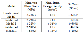
Table 2. Responses of the Three Joint Models to a Load of 1 N along Fore/Aft Direction (Numbers in Parentheses Represent Percent Changes relative to that of the Unreinforced Model)
 |
| |
|
Table 3. Responses of the Three Joint Models to a Load of 0.1 N-m about B-Pillar Path Direction (Numbers in Parentheses Represent Percent Changes relative to that of the Unreinforced Model)
 |
| |
|
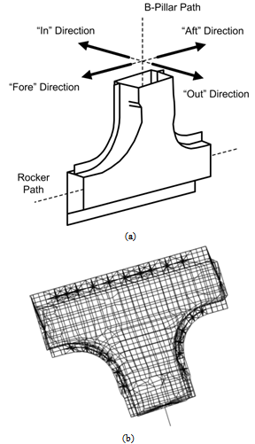 | Figure 3. (a) B pillar to rocker joint and loading direction references and (b) finite element model of the joint. The mechanical properties of the material are as follows: Young’s modulus E=2.069e+5 MPa, Possion’s ratio = 0.292, and material density = 7850 kg/m3 |
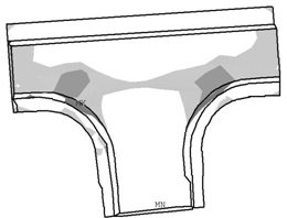 | Figure 4. Visual rendering of the joint strain energy changes due to thickness modification of each shell element.  |
3.2. Light-Duty Truck Cab
Global level gauge sensitivity characterizes the stiffness of an entire automobile body as a function of the panel thickness. One way of approximating global gauge sensitivity is by using[5]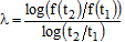 | (10) |
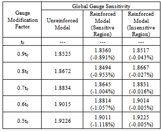
where f is a thickness-related structural parameter (bending stiffness, for example). Eq. 10 evaluates λ using two known values of the thickness (t1 and t2) and corresponding structural parameter values (f(t1) and f(t2)). Global gauge sensitivity of a truck cab will be computed in this example for illustrating the effect of local architecture changes on the overall cab stiffness.Local gauge sensitivity analysis is performed for the cab to locate good regions for applying efficient reinforcements. A detailed finite element model is developed for this cab with proper boundary constraints at the four cab/frame mount locations. The cab is bended by applying equivalent downward forces at the two rocker panels. The bending stiffness of the cab is defined in this study as the quotient of the applied force on the rocker and the corresponding deflection at the same location. The procedure of local gauge sensitivity analysis for the cab is the same as that for the above B pillar to rocker joint. Figure 5 shows the visual rendering of the analysis results. Again the regions with high values make them ideal for applying reinforcements. To illustrate application of this rendering plot, two enhanced cab models are developed for comparison by applying bulkheads to two different regions on the B pillar: one has high values (sensitive region) and the other has relatively low values (insensitive region). The bulkhead is modelled as a rigid distributed connection that maintains the shape of the cross-section at the application location, see Figures 6a and 6b. First, a series of down-gauging analyses is performed to calculate the bending stiffness of the unreinforced and the two reinforced cab models in response to gauge modifications ranging from the original to one-half of the original sheet metal thickness. Next, the global gauge sensitivity values of each cab model are determined based on sequential pairs of known bending stiffness/thickness values, see Table 4. With this approach, the global gauge sensitivity value at 0.9t0 is computed using the stiffness values at 1.0t0 and 0.9t0, the global gauge sensitivity value at 0.8t0 is computed using the stiffness values at 0.9t0 and 0.8t0, and so forth. Without cab bending stiffness value at 1.1t0, it is impossible to calculate global gauge sensitivity at t0, explaining the missing values in Table 4.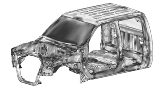 | Figure 5. Visual rendering of the cab strain energy changes due to thickness modification of each shell element.  |
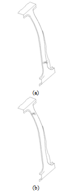 | Figure 6. Bulkhead applied to (a) sensitive region and (b) insensitive region on the B pillar of the truck cab |
Global gauge sensitivity measures the non-uniformity of the internal load distribution in the body structure, with greater non-uniformities corresponding to higher gauge sensitivity values. Low global gauge sensitivity values, therefore, imply an automobile BIW with low degree of non-uniformity of the internal load distribution and high efficiency of material usage. It can also be interpreted that reducing the global gauge sensitivity value is equivalent to increasing the overall body stiffness-to-weight ratio. By comparing the reductions in the global gauge sensitivity values of the two reinforced cab models in Table 4, one can conclude that it is more efficient to apply reinforcements in the sensitive regions that are identified by local gauge sensitivity analysis.A couple acting on the two rockers twists the cab about its longitudinal axis. The torsional stiffness of the cab is defined in this study as the quotient of the couple and the angular rotation of the line connecting the load center of action. While not presented here, it is found that the above conclusion for the cab under bending load holds true for the torsional load case as well, validating the effectiveness of the local gauge sensitivity analysis in supporting the vehicle design optimization.Table 4. Changes in the Global Gauge Sensitivity of the Three Cab Models due to Gauge Modifications (Numbers in Parentheses Represent Percent Changes relative to that of the Unreinforced Model)
 |
| |
|
4. Conclusions
Gauge sensitivity technologies may be applied at different vehicle body architecture levels. Previous studies focus on the theory, validation and application of gauge sensitivity methodologies at the global and component level. Local gauge sensitivity is defined and evaluated in this paper with the use of the strain energy density concept. Visual rendering of the total strain energy changes due to thickness change in each element is developed to support collaborative assessment of the resulting local gauge sensitivity data. The paper concludes with example case studies to validate the usage of local gauge sensitivity analysis to design architecture with optimum stiffness-to-weight ratio.
ACKNOWLEDGEMENTS
This research is funded by the 2012 PRF Summer Faculty Grant. The support is gratefully acknowledged.
References
| [1] | K. Salonitis, J Pandremenos, J. Paralikas, and G. Chryssolouris,“Multifunctional materials used in automotive industry: a critical review”, Engineering Against Fracture: Proceedings of the 1st Conference, pp. 59-70, 2009. |
| [2] | A. Kelkar, R. Roth, and J. Clark, “Automobile bodies: can aluminium be an economical alternative to steel?”, Springer Publishing, JOM, August, pp. 28-32, 2001. |
| [3] | M. Kulekci, “Magnesium and its alloys applications in automotive industry”, International Journal of Advanced Manufacturing Technology, Vol. 39, pp.851-865, 2008. |
| [4] | R. Patton, and F. Li, “Causes of Weight Reduction Effects of Material Substitution on Constant Stiffness Components”, SAE Paper 2002-01-1291, 2002. |
| [5] | G. Prater, SY. Zhang, A. Shahhosseini, and G. Osborne, “Application and experimental validation of gauge sensitivity indices for vehicle body structure optimization’, SAE paper number 2008-01-0883, 2008. |
| [6] | G. Jang, Y. Chon, and G. Choi, “Discrete thickness optimization of an automobile body buy using the continuous-variable-based method”, Springer Publishing, Journal of Mechanical Science and Technology, Vol. 22, pp. 41-49, 2008. |
| [7] | X. Liu, “Shape optimization of car body structure based on uniform design method”, in Proceedings of IEEE Vehicle Power and Propulsion Conference, pp. 1-4, 2008. |
| [8] | O. Olatunbosun, A. Gauchia, M. Boada, and V. Diza, “Dynamic Performance Analysis of a Light Van Body-In-White Structure’, in Proceedings of the Institution of Mechanical Engineers”, Part D: Journal of Automobile Engineering, Vol. 225, No. 2, pp. 167-177, 2011. |
| [9] | F. Li, R. Patton, and K. Moghal, “The relationship between weight reduction and force distribution for thin wall structures’, Elsevier Publishing, Thin-Walled Structure, Vol. 43, pp.591-616, 2005. |
| [10] | SY. Zhang, G. Prater, A. Shahhosseini, and G. Osborne, “Experimental validation of structural gage sensitivity indices for vehicle body structure optimization”, John Wiley & Sons, Experimental Techniques, Vol. 32, Issue 5, pp.51-54, 2008. |
| [11] | SY. Zhang and G. Prater, “A study of the effect of elastic instability on stiffness-based gauge sensitivity indices for vehicle body structure assessment”, Elsevier, Thin-Walled Structures, Vol. 47, pp.15901-1596, 2009. |
 Abstract
 Reference
 Full-Text PDF
 Full-text HTML