Basim Mohammed Fadhil
Petroleum Engineering Department, Koya University, Erbil, 964, Iraq
Correspondence to: Basim Mohammed Fadhil, Petroleum Engineering Department, Koya University, Erbil, 964, Iraq.
| Email: |  |
Copyright © 2012 Scientific & Academic Publishing. All Rights Reserved.
Abstract
A finite element method has been used to investigate and analyze the effect of the plies stacking sequences for E-glass /epoxy and tube geometry under impact loading with low velocity. Crossply, multi, and angle ply symmetric stacking sequences has been taken herein to investigate . ANSYS- LS-DYNA explicit finite element program was used to perform the pre-processing and post-processing impacting loading procedure and the damage it caused. It was found that the stacking sequences of the plies and the tube geometry play an important role in the mechanical behaviour of the tube under impact loading.
Keywords:
E-Glass/Epoxy, Tube Geometry, Impact Loading
Cite this paper: Basim Mohammed Fadhil, Effect of Plies Stacking Sequence and Tube Geometry on The Crush Behavior of Tube under Low Velocity Impact –Numerical Study, International Journal of Mechanics and Applications, Vol. 3 No. 2, 2013, pp. 44-51. doi: 10.5923/j.mechanics.20130302.02.
1. Introduction
Usually the Composites materials are manmade where the components are blended to get the best characteristics of each. Its stiffness and strength are comparable to traditional metals that they replace. This gives a great opportunity to the engineers to create safer and stronger products. Composite material behavior differs strongly from isotropic materials. With classical laminate plate theory a considerable deal of idea into distinction the static behavior of composite laminates. Classical laminate plate theory has been very beneficial in supplying accurate analyses in the fields of transverse particle impact damage and damage from various combinations of static loading[1]. Wide range of automotive and aerospace applications uses fibre reinforced composite materials as structural elements to absorb collapsible impact energy. Since they supply important economical and functional worth such as boost strength and durability, strength /weight increasing and lower fuel consumption[2,3].A drop-weight impact tests and compression after impact (CAI) tests on carbon/epoxy laminates are investegated. The experiments were performed on specimens of two different geometries (rectangular and circular), according to two ASTM standards. Global buckling due to the small thickness was the dominated behaviour of laminates under compression was characterized. Finite element analysis was helpful in the interpretation of strain recordings in different positions of the laminates[4].A traditional laminate and two deferent stacking sequence alternative layups were tested experimentally under low- velocity impact and compression-after-impact loads. A Comparison has been conducted between impact resistance and damage tolerance characteristics.[5]An evaluation of the impact behavior of a tested laminates by innovative numerical methods has been conducted. An explicit finite element method and used in the simulation of low-velocity impact events on composite laminate. The accuracy achieved with this method increases the reliability of numerical methods in the simulation of impact loads enabling the reduction of the time and costs associated with mechanical testing.[6].Finite element method has been used to investigate a fiber-reinforced composite plates subjected to low velocity impact. A parametric analysis shows that the increase in the percentage of the 90 plies increases the contact force implying a reduction in the rigidity of the laminate.[7]A comparison between finite element simulation and experimental tests for polymer–matrix composite laminates reinforced by unidirectional fibers has been performed in order assess the accuracy of the prediction of ply failure mechanism and delamination.[8] An investigation presents the essential steps to design specific lightweight impact attenuators. By explicit FE code LS-DYNA and mathematical formulation it is possible to model and realise simple CFRP tubular structures. Also, experimental dynamic tests are conducted by use of a drop weight test machine. Achieving a good agreement of the results in previously mentioned analyses, follows to the design of impact attenuator with a more complex geometry[9]. The aim of this work is to investigate and analyze the effect of plies stacking sequences with two deferent tube (circular and square) geometry on the mechanical behavior and crushing characteristics of thin-walled tube, by simulating the response of these tubes subjected to low velocity axial loading, using ANSYS-LSDYNA finite element code.
2. Numerical Analysis
The numerical analysis begins with finite element analysis and laminate constituent relationships. Laminate constituent formulas supply an effective, yet highly efficient, means of characterizing the behavior of 3-D composite materials as if the composite are consisted of multi-layers of 2-D model. When the means of characterizing the general mechanical behavior of a laminated composite are provided, FEA can then be conducted. Many FEA codes are available for the numerical analysis of composites materials. These softwares mostly use numerical approximation to simulate and material and structural response. Nevertheless, very few of these methods combine the layered analysis resulting from the laminate constituent formulas to model composite material and structural behavior.
3. Finite Element Model
In the present work two different 3D models have been built as a contact pairs, each pair consist of impactor as a rigid part and target as a contact part .The impactor (rigid part) was a block with 0.18x0.18x0.008m in dimensions and about 40 kg mass figure (1) .The target was an a tube with two geometries, the first is circular tube with 0.1m diameter while the second one is a square tube with 0.0785 m for dimensions, both of them with 0.1 m height and 0.00132 m thickness. The first model has been used a circular tube and a square tube for the second model as targets (contact parts). Figure (2(a),(b)).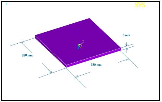 | Figure 1. Impactor as a rigid part |
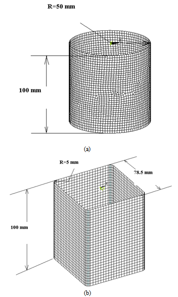 | Figure 2. Fininte element model for tubes, a) circular. b) square |
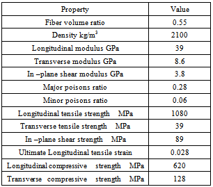
In order to build a 3D finite element models, SHELL163 element with multi-layer has been used to mesh the tube and SOLID 164 elements to mesh the impactor. The using of shell163 element provides a wide ability to composite materials modeling with a big capability to mesh multi-layer model with different orientations. The 3D finite element models have been built by ANSYS- LS-DYNA Code. ANSYS-LS-DYNA is an explicit finite element program with powerful pre- and postprocessing capabilities was used to perform the simulation work for impact loading behavior and the damage it caused. A unidirectional composite material with 8 plies made of epoxy as matrix and E-glass fiber as a reinforcement the properties are in table 1.The E-glass/epoxy composite material tubes which used herein to investigate the mechanical behavior under impact loading by drop weight was consisted of 8 balanced symmetric stacking sequences plies; each ply with thickness equal to 0.0165 mm[10] and the total thickness of the panel was 1.32 mm.. The mesh was consisted form 3704 element and 3628 node, this number provides good accuracy of results. The drop weight velocity (impactor velocity) was 3 m/s and the total time that has been taken as impact period was 0.1 second .All the degree of freedom were fixed (equal to zero) on the nodes of tube bottom.Table 1. Properties of E-Glass/Epoxy Composite Material[10]
 |
| |
|
Four different plies stacking sequences were used in this study for each model, as follows: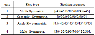
4. Results and Discussions
Herein we will discuss the results which induced in e-glass /epoxy composite material and the failure mode adopting the tube geometry.
4.1. Reaction Force Versus Displacement
4.1.1. Circular Tube
Generally, the reaction force represents is essential parameter for characterize the best plies stacking sequence in such investigations and may be form the most important factor for comparing.So, we start with reaction force versus displacement relationships to illustrate the mechanical behavior of the target (circular tube) with four different plies stacking sequences.From the figure (3), obviously the higher reaction force is at the collision moment then decline strongly and start increases with increasing displacement. This phenomenon is involved all cases except case 2. The figure shows that case 1 has the highest value for reaction force followed by case 4 and 3, while case 2 considered the worst case. Apparently, case 1,4,3 have the same behavior regardless the reaction values, concentrated on :highest reaction value at collision moment, followed by decline in this value and start to increase again with squeezing the tube of a specific displacement, eventually the tube recover some of this displacement. We can interpret this, as these three plies stacking sequences of the tube have the ability to absorb the largest amount of kinetic energy for the impactor as latent energy and then release it again to regain the lost part of displacement.
4.1.2. Square Tube
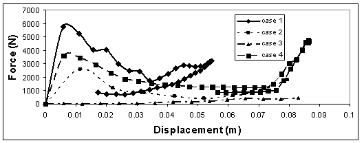
Figure (4) illustrates the relationship between reaction force and displacement for square tube. For the second time, we can be observed that the mechanical behavior of square tube changes with changing plies stacking sequences. The highest value of reaction force was for case 1 again followed by case4 and 2, while the lowest value was for case 3 this time. Also the tube with case 1 recovers its displacement rapidly than case 4 but with fully destroyed (without any recovery) for cases 2and 3. 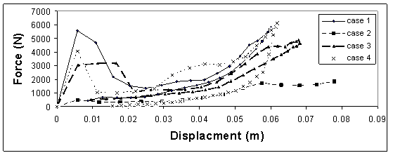 | Figure 3. Reaction force vs displacement for circular tube |
 | Figure 4. Reaction force vs displacement for square tube |
4.2. Comparison between Circular Tube and Square Tube
4.2.1. Case 1
With figure (5), the behaviour nature for both tubes is substantially alike, both of them recovers most displacement, just the square tube suffers a gradually decreasing in reaction force. Therefore we can say that, there is no strong effect for the tube geometry with this plies stacking sequences on the mechanical behaviour and the reaction force values.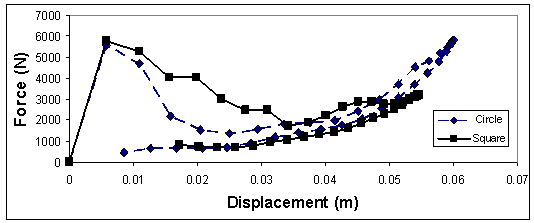 | Figure 5. Reaction force vs displacement for square tube and circular tube with case 1 |
4.2.2. Case 2
Apparently with case 2 of stacking sequence there is a big role of the geometry on the tube behavior and reaction force value as well. Where the reaction force of the square tube is greater than the circular tube. Figure(6).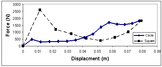 | Figure 6. Reaction force vs displacement for square tube and circular tube with case 2 |
4.2.3. Case 3
With this case of stacking sequence, the circular tube has a strong behavior versus the square one represented by the reaction force value comparable with counterpart for the square tube, while a very low value of reaction force has been showed by the square tube. Figure (7) 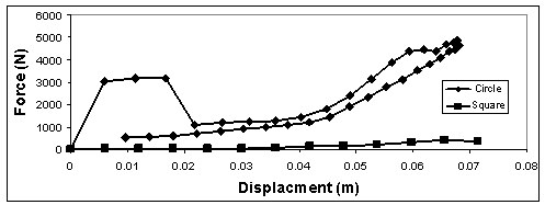 | Figure 7. Reaction force vs displacement for square tube and circular tube with case 3 |
4.2.4. Case 4
Through the figure (8), both tubes have (approximately) the same reaction force value and the same crush behavior, except one difference, the square tube has a gradually decreasing in reaction force while a sharp decreasing for circular one.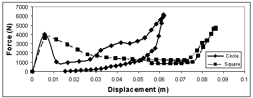 | Figure 8. Reaction force vs displacement for square tube and circular tube with case 4 |
4.3. Progressive Collapse by Visual Comparison of Images
The produced images of impact dynamics sequence provide a great opportunity to know very accurately the nature of the tube behavior under impact load. Figures (9, 10) show impact history for progressive collapse for four types of stacking sequence for circular tube and square tube respectively.
4.3.1. Circular Tube
In the first case, figure( 9a), the tube suffers buckling at the 0.002 sec. where the maximum value of reaction force (5547.4N) followed the accession of its upper edge as a result of bending to reach minimum reaction force (1360 N) at 0.01 sec.With figure (9b), where case 2,the upper edges bends outward with a 489 N reaction force leading fully collapse of the tube.The tube with case 3, suffers buckling where reaction force was 3178.8 N followed by accession of its upper edge leads to squeeze the tube. Figure (9c)The tube behavior in case 4 was almost similar to case 1 but the maximum reaction force decline sharply the case 1followed by gradually increase to squeeze the tube ( figure d).
4.3.2. Square Tube
Again, herein the plies stacking sequence plays a role in the values of reaction forces and the mechanical behavior as well, this is apparently in figure (10),where tube with case 1 got the highest reaction force value by case4,case2,and finally case 3. The mechanical behavior of square tube under impact load is not similar for the circular tube although there also appears at first sight, where an obvious difference in terms of the values of reaction force as well as in the behavior of the tube under impact load.The most important differences are: the order of cases in terms of the highest value of reaction force was not the same, and a gradual decline of the reaction force for all cases except case 3 was in the square tube, while a sharp decline of the reaction force for all cases except case 2 was in the circular tube. 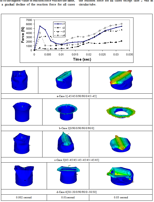 | Figure 9. Impact history for progressive collapse for four types of stacking sequence for circular tube |
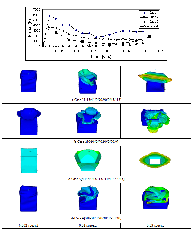 | Figure 10. Impact history for progressive collapse for four types of stacking sequence for square tube |
5. Conclusions
We have addressed in this work the problem of effect of plies stacking sequence and the tube geometry on the mechanical behaviour in E-glass/epoxy composite tubes. First, let’s classifies the conclusion into categories in term of geometry.
5.1. Circular Tube
1. The results show that the tube with Multi- Symmetric[-45/45/0/90/90/0/45/-45] (case 1) has the highest reaction force value.2. The tube with case 2 (Crossply–Symmetric[0/90/0/90/90/0/90/0] has lowest reaction force value.3. The mechanical and crush behaviors are defers from stacking sequence to another.4. The buckling is the main feature of crush behavior of the circular tube.5. A sharp decline of reaction force with time has been observed.
5.2. Square Tube
1. With this geometry, the tube still has the highest reaction force with Multi- Symmetric[-45/45/0/90/90/0/45 / -45] (case 1).2. The tube with angle-PlySymmetric[45/-45/45/-45/-45/45/-45/45]) (case 3) has lowest reaction force value.3. The square tube has different behavior with different stacking sequences.4. A gradual decline of the reaction force versus time.Second, from above, the tube geometry has a very important role to specify the crush behavior and the reaction force value. Eventually, square shape of tube that subjected to low velocity impact load is preferable in design for such cases of load.
References
| [1] | JN Reddy. Mechanics of laminated composite plates: theory and analysis. Boca Raton, FL: CRC Press; 1996. |
| [2] | Mamalis A, Robinson M, Manolakos D, Demosthenous G, Ioannidis M, Carruthers J. Review: crashworthy capability of composite material structures. Compos struct 1997;37: 109–34. |
| [3] | Thorton P, Jeryan R. Crash energy management in composite automotive structures. Int J Impact Eng 1988;7:167–80. |
| [4] | Daniele Ghelli, Giangiacomo Minak,” Low velocity impact and compression after impact tests on thin carbon/epoxy laminates”, Composites: Part B 42 (2011) 2067–2079. |
| [5] | C.S. Lopes, O. Seresta, Y. Coquet, Z. Gürdal, P.P. Camanho, B. Thuis “Low-velocity impact damage on dispersed stacking sequence laminates. Part I: Experiments”, Composites Science and Technology 69 (2009) 926–936 |
| [6] | C.S. Lopes, P.P. Camanho, Z. Gürdal, P. Maimí, E.V. González,” Low-velocity impact damage on dispersed stacking sequence laminates. Part II: Numerical simulations”, Composites Science and Technology 69 (2009) 937–947 |
| [7] | R. Tiberkak, M. Bachene, S. Rechak, B. Necib,” Damage prediction in composite plates subjected to low velocity impact”, Composite Structures 83 (2008) 73–82 |
| [8] | E.V. González , P. Maimí, P.P. Camanho, A. Turon, J.A. Mayugo,” Simulation of drop-weight impact and compression after impact tests on composite laminates”, Composite Structures 94 (2012) 3364–3378. |
| [9] | Jovan Obradovic , Simonetta Boria , Giovanni Belingardi,” Lightweight design and crash analysis of composite frontal impact energy absorbing structures”, Composite Structures 94 (2012) 423–430. |
| [10] | Isaac M. Daniel,Ori Ishai "Engineering Mechanics of Composite Materials", Oxford University Press.(1994). |
 Abstract
 Reference
 Full-Text PDF
 Full-text HTML