O.K. Ajayi 1, L.O. Adekoya 2
1Mechanical Engineering Department, University of Ibadan, Ibadan, Nigeria
2Obafemi Awolowo University, Ile-Ife, Nigeria
Correspondence to: O.K. Ajayi , Mechanical Engineering Department, University of Ibadan, Ibadan, Nigeria.
| Email: |  |
Copyright © 2012 Scientific & Academic Publishing. All Rights Reserved.
Abstract
This work was done in response to the need of reducing drudgery in transporting books within the school library. This is because book shelves run through the length of the buildings as well as reading tables. The arrangement of books are as such that the reader might need a book or material in another floor apart from the one where he is reading, this reduces drudgery for the library attendants to shuttle between floors to get required materials to readers. A machine otherwise called a dumbwaiter was thus designed having the capacity of lifting 100kg load. A prototype was constructed and the performance evaluated with three ser of loads. The floor selection was controlled making use of limit switches placed near each floor landing.
Keywords:
Dumbwaiter, Floor Selection, Limit Switches
Cite this paper: O.K. Ajayi , L.O. Adekoya , Design and Prototype Construction of a Dumbwaiter (Book Lift), International Journal of Mechanics and Applications, Vol. 3 No. 1, 2013, pp. 31-34. doi: 10.5923/j.mechanics.20130301.05.
1. Introduction
Library is the collection of books for reading or studying. It is also the building or room in which such a collection is kept. In 1793, Ivan Kulibin created an elevator with the screw lifting mechanism for the Winter Palace of Saint Petersburg. In 1816, an elevator was established in the main building of sub Moscow village called Arkhangelskove and in 1823, an “ascending room” made its debut in London. In 1874, J. W. Meaker patented a method which permitted elevator doors to open and close safely as US Patent No. 147,853[1]. In 1929, Clarence Conrad Crispen, with Inclinator Company of America, created the first residential elevator and he also invented the first inclined stairlift.The need for vertical transportation is as old as civilization. The lifting of water was the first preoccupation of early humans as they entered the era of systematic agriculture. Over the centuries, mankind has employed ingenious forms of lifting. The earliest lifts used man, animal and water power to raise loads[2]. Nowadays, high-rise buildings are normally serviced by elevators, as the vertical traffic transport equipment[3]. There are several kinds of mechanisms for vertically transporting people and goods; Lift or elevator depending on the country, dumbwaiters, conveyors and cranes amongst others, to different floors or levels in a building or a mine[4].The first electric elevator was constructed by Werner von Siemens in 1880[5]. A library is a collection of sources, resources, and services, and the structure in which it is housed: it is organized for use and maintained by a public body, an institution, or a private individual. In the more traditional sense, a library is a collection of books. The term can mean the collection, the building that houses such a collection or both. Types of library are; national library, research library, academic library, public library, school library, special library.Some of the more important libraries include the following; the Bodleian Library at Oxford, the Library of the British Museum, the Mazarine Library in Paris, and the National Central Library in Italy, the Prussian State Library, the M.E. Saltykov-Shchedrin State Public Library of St. Petersburg, amongst others[6].Transportation inside the library has to be made more convenient and efficient. This will also improve the library services such as; lending of reading and learning materials (books, tapes, CDs, thesis and others) as well as returning them, collection and distribution of new books with proper organization, handling and accounting for books in the library[6]. An elevator system for a two storey building includes two carriages each of which is moveable from the upper floor to the lower floor[5]. The earliest ones adopted the hoist, while recent ones make use of automatic safety devices. Elevators consist of a platform or car travelling in vertical guides in a shaft or hoist way, with related hoisting and lowering mechanisms as a source of power. The development of the modern lift made architects’ design of multi-storey buildings practicable[4].Parameters such as the elevator capacity and running speed must be confirmed during building design. This requires that the elevator traffic should be analysed reasonably[7, 8]. In 1852, Elisha Otis invented the first safety brake for elevators[9] and exhibited the lift equipped with a device known as “safety” to stop the fall of the car in the event the hoist rope breaks and gave impetus to lift construction[1]. The lifetimes of elevator control systems are typically 15-25 years, and the system architecture of the currently operating elevator base is highly different than that of the old one[10].The first hydraulic industrial lift powered by water pressure appeared in 1846[2]. The modern hydraulic system are found in scenic elevators in superstores or historical buildings[11, 12, 13], stage elevators[14], ship elevators[15, 16] and elevators for disabled persons[17] amongst others. Hydraulic elevators can be adapted to architectural design requirements without compromising energy saving and efficiency requirements[18].The objectives of this project are to design and construct a prototype of the machine that will vertically transport books from the ground floor of a multi-storey library building to the upper floor to reduce the drudgery in vertically transporting books between the floors.
2. Design Considerations
The design is for a device that can lift a load from one floor to another floor, ground floor to any other floor in a two-storey library building.The following considerations are necessary in determining the suitable means of achieving this with their weights; Ease of installation in buildings especially already erected two -storey library building (8), Noiselessness (5), Affordability: Parts and Construction (6), Safety for users (8), Reliability and Efficiency (7), Ease of Operation (7), Ease of Installation (8), Available Technology (9).The following methods can be adopted; traction method, hydraulic system or the manual rope and pulley method. The traction method was selected from the outcome of a Decision Matrix comparing the three possible methods.
3. The Load Design
The design load was calculated by taking a factor of safety 2 or 2.5 times the factor of safety given in tables thus; design load = 12 x the weight of the (carriage + books)
4. Cable Design
From the table of steel wire suspension ropes and the tensile strength for lifts, elevators and hoists; | (1) |
The torque to be transmitted by the pulley is  | (2) |
 | (3) |
 | (4) |
 | (5) |
Additional load due to acceleration; | (6) |
Effective load on rope during acceleration of load (during first 0.6s after starting) | (7) |
The combination of these equations determines the factor of safety. If the factor of safety is between the recommended specifications, then it is safe to use the cable specification from tables. The power required to drive the pulley is  | (8) |
5. Gear Design
The gear transmits the same power as the pulley. Once the power to be transmitted through the gear is known, the torque acting on the pinion is calculated thus; | (10) |
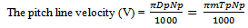
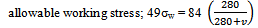
Then, the diameter of the gear is also determined using the velocity ratio (V.R). The diameter of the gears was determined through; | (11) |
 | (12) |
 | (13) |
 | (14) |
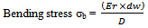
for the outside diameter for the pinion; 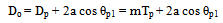 | (15) |
6. Shaft Design for Pulley
Due to the type of operation it would perform, it was decided that the pulley be made of cast iron: it should be able to absorb shock loads and should also be light enough and be tough. It would have two grooves to accommodate two steel cable wire ropes passing over it. This is so that the load would be distributed and not concentrated at a point and to also reduce the power required to raise the load. The sheave diameter is designed to be fairly large to reduce the bending stresses in the ropes when they bend around the sheaves, large diameters from the tables would be used to give better and economical service.Since the sheave is for a light service, cast iron is used. From the table of recommended values for Km and Kt; under rotating shafts and suddenly applied load with minor shocks only: the combined shock and fatigue factor for bending (Km) = 1.5 and the combined shock and fatigue factor for torsion (Kt) = 2.0 while the transmitted torque is  | (16) |
The torque to be transmitted by the pulley is (WE - WC) x radius of pulley the power to required to drive the pulley is  | (17) |
The bending moment of this structure is needed in determining the diameter of the shaft; the equivalent bending moment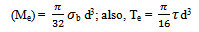 | (18) |
7. Spring Design
Twisting moment on the spring 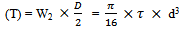 mean diameter of the spring coil; D = 5 ×douter diameter of spring coil Do = D + dinner diameter of spring coil Di = D – d,the number of turns of spring is calculated from the axial deflection;
 | (19) |
 | (20) |
8. Floor Selection
A set of sensors (micro switches) attached to the guide rails near the landing of each floor serves as the floor selectors. As the carriage approaches the required floor, it brushes over the switch, and this in turn puts off the prime mover. The switches were bolted to angle bars in slots created on the left side of the carriage guide rail. Their operation is controlled by a central electric control panel on one side of the machine. The circuit in the control panel consists of relays, capacitors, resistors, switches and board among other miscellaneous.
9. Results
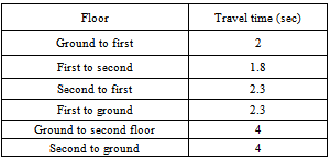
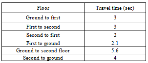
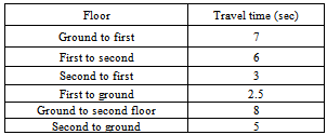
The following are the results of the prototype constructed and the tests carried out on it.Maximum travel height =0.95m, Maximum weight transported =1.5 kg, Travel time versus weights: This is presented in the following tables; The tests showed that the speed of the carriage as it ascends reduces as the load increases and increases as it descends. The time taken to ascend increases with the floor travelled. This is caused by the Carriage dimension. Table 1. Results for weight 0.33kg
 |
| |
|
Table 2. Results for weight 0.390kg
 |
| |
|
Table 3. Results for weight 0.770kg
 |
| |
|
Table 4. Results for weight 1.500kg
 |
| |
|
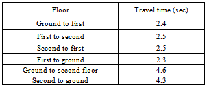
In Fig. 1, it takes the same time to ascend and descend the ground floor through the second floor. It also takes the same time to descend second floor to first floor and the first floor to the ground floor. This is as a result of the Newton’s law of motion.In figs. 2, 3 and 4, there are differences in most of the travel times. In fig 2; it is only the travel between the second and first floor (descent and ascent) that is the same but in fig 3, it takes the same time to ascend the first floor and also second floor.Fig. 4 has the highest weight: it shows no similarity in time travel. At this weight, the dumbwaiter is actual getting to its capacity limit. Here, the time of travel has greatly increased compared to the previous lighter weights.
10. Conclusions
The dumbwaiter (book lift) is simple in operation and stress relieving as well as reducing drudgery in vertically transporting books between stairs in a multi-storey library building. The traction method used was very effective. The floor selection design used was purely electrical, making use of limit switches placed at each floor. The design was for a 100kg weight, the shaft design was 50mm according to the required factor of safety for elevator design. The constructed prototype was able to transport 1.5kg mass through 0.95m which is the height for the second floor. Although there were variations in the travel times with the smaller weights, it can be seen that the performance of the dumbwaiter becomes predictable at 1.5kg weight, which means that it got to its optimal working condition at this weight. This means there was a balance between the carriage and the counterweight at this point, thus reducing energy loss due to under utilization. The maximum travel time was 8secs and it was noiseless despite the parts moving against each other.Most libraries are multi-storey; therefore the following are recommended;Further works can be carried out to refine the constructed prototype especially the power system: Hydraulic and Pneumatic methods can be adapted into the design, as well as combined hydraulic-rope method. The carriage can also be improved upon: automatic opening of the carriage door when it gets to the appropriate floor and alerting the personnel at each floor. This design can be used as a template for library buildings of more than two-storeys. Most of the recent works in library services optimization has been in automating the library operations and e-library designs. Libraries that do not have (working) elevators should be retrofitted with a dumbwaiter; this would make the library services more effective and appealing as well as reducing noise due to human movement through the stairs in the library. The elevator has been given much priority over the years, but there is no need to expend much energy in transporting books in between stairs, instead designs should be made for transporting only reading and studying materials.
ACKNOWLEDGEMENTS
I acknowledge the department of Mechanical Engineering department, University of Ibadan.
References
| [1] | Microsoft 2008. ‘Library’, ‘Transportation’, ‘Vertical transportation’, ‘Lift’. Microsoft Encarta Encyclopedia Standard. 2008 Ed. |
| [2] | Otis Elevators. 2004. A history of lifts, hoists and early elevators: About Elevators. Retrieved fromwww.otisworldwide.com on June 14, 2009. |
| [3] | Lee, Y., Kim, T. S., Cho, H., Sung, D. K. and Choi, B. D. 2009. Performance analysis of an elevator system during up-peak. Journal of Mathematical and Computer Modeling. Elsevier. 49(2009)423-431. |
| [4] | George Johnson Service Lift. 2007. Domestic lift. A brochure of domestic lifts from George Johnson Service lifts and dumbwaiters. Retrieved fromhttp://www.george-johnson-lifts.co.uk on May 14, 2009. |
| [5] | United States Patent. 2009. Elevator system for a building-United States Patent 5152374. |
| [6] | Wikimedia. 2009. ‘Library’, ‘Elevator’. Wikimedia foundation Inc. Retrieved from Wikipedia free Encyclopedia at en.wikipedia.com on May 14, 2009. |
| [7] | Barney, G.C. and Santos, S.M. 1975. Improved traffic design methods for lift system. Journal of Building Science. 10(4)277-285. |
| [8] | Barney, G.C. and Santos, S.M. 1985. Elevator Traffic Analysis, Design and Control. Peregrinus, London. |
| [9] | The Great Idea Finder. 2007. Invention: Elevator history. Retrieved from www.ideafinder.com on May 14, 2010. |
| [10] | Seppo, J.O. 1997. Evolutionary modernization of large elevator groups: toward intelligent Mechatronics. Journal of Mechatronics. Pergamon. 8(98)37-46. |
| [11] | Hayes 1999. In Li, K. (2001), Journal of Control Engineering Practice. Elsevier |
| [12] | Anon 1989. In Li, K. (2001), Journal of Control Engineering Practice. |
| [13] | Schneider 1986. In Li, K. (2001), Journal of Control Engineering Practice. Elsevier. |
| [14] | Anon 1974. In Li, K. (2001), Journal of Control Engineering Practice. |
| [15] | Laurent, J., de Fays, R. and Dambrain, M. 1988. In Li, K. (2001), Journal of Control Engineering Practice. Elsevier. |
| [16] | Brouet. 1998. In Li, K. (2001), Journal of Control Engineering Practice. |
| [17] | Iwainsky, H., Lauermann, J. and Spanier, H. 1990. In Li, K. (2001), Journal of Control Engineering Practice. Elsevier. |
| [18] | Schneider, K., 1987. Energy saving for hydraulic lifts. Elevator world, 35(3)52-57. |
| [19] | Khurmi, R.S. and Gupta, J.K. 2004. A text of Machine Design.13th ed. New Dehli: Eurasia. |
 Abstract
 Reference
 Full-Text PDF
 Full-text HTML