Ivan Virgala , Michal Kelemen
Department of applied mechanics and mechatronics, Faculty of mechanical engineering, Technical university of Košice, Košice, 042 00, Slovakia
Correspondence to: Ivan Virgala , Department of applied mechanics and mechatronics, Faculty of mechanical engineering, Technical university of Košice, Košice, 042 00, Slovakia.
| Email: |  |
Copyright © 2012 Scientific & Academic Publishing. All Rights Reserved.
Abstract
The paper deals with experimental friction identification method of a DC motor. For precise positioning tasks a friction phenomenon plays a large problem. For this a friction has to be identified and subsequently compensated if it is important. At first the paper deals with basic friction models. In the next section the DC motor mathematical model is stated. The DC motor friction identification is based on basic Newton´s motion equation of motor. The friction course by means of Matlab and measuring card is measured. For experimental results verification the simulation of mathematical model is used in comparison with real motor. The results are in the graph shown.
Keywords:
DC Motor, Friction, Identification, Stribeck Effect
Cite this paper: Ivan Virgala , Michal Kelemen , Experimental Friction Identification of a DC Motor, International Journal of Mechanics and Applications, Vol. 3 No. 1, 2013, pp. 26-30. doi: 10.5923/j.mechanics.20130301.04.
1. Introduction
Nowadays there are a lot of tasks in mechatronics which concern precise positioning in mechanisms. Mostly a friction phenomenon plays large problem in these tasks and many times it has to be compensated. The friction is a phenomenon which is not easily describable. For these purposes there were a lot of friction models and compensating schemes described.[1][2]Friction can be compensated by several methods and than can be achieved desired behaviour for precise position control with suitable control strategy. [7]In this study a friction of a DC motor will be investigated. A mathematical model of a DC motor is well known and if we know to describe a friction in motor we can easily control angular velocity or angular position.
2. Friction Models
Over the past few decades friction was studied extensively in classical mechanical engineering. Friction is tangential reaction force that is present during the relative motion of surfaces in contact. These reaction forces are the result of many different mechanisms, which depend on properties of the bulk and surface materials of the bodies, displacement and relative velocity of the bodies, contact geometry and topology and the presence of lubrication.[3]A friction in the mechanical parts of the moving systems causes failures especially during precise position regulation. Its compensation can be reaches by design solutions however they do not eliminate friction course nonlinearity within low velocities.[4]In the next section will be discussed different kinds of friction models namely, stiction, Coulomb friction model, viscous friction model and Stribeck effect.
2.1. Stiction
Static friction models only have a static dependence on velocity. This kind of friction occurs if a mass velocity equals zero and it acts against a relative mass motion. The force required to overcome the static friction and initiate motion is called the breakaway force and can be expressed as[5]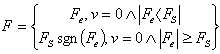 | (1) |
Where Fe and FS are external force affecting the body and static friction force, respectively. After overcoming static friction force FS the starts move.The main disadvantage of static friction model is discontinuity at zero velocity. The discontinuity at zero velocity also leads to numerical difficulties. To overcome this problem the discontinuous behavior near zero velocity is approximated by means of a continuous function like arctan function with a very steep slope. However, a very steep slope around zero velocity can result in very short integration time steps which slow down or even stop simulation.[4]
2.2. Coulomb Friction Model
A Coulomb friction model does not depend on a velocity magnitude but only on velocity direction – sgn(v). Coulomb friction coefficient fC is usually lower than static friction coefficient fS for the same materials. Coulomb friction is also known as kinetic friction or dynamic friction and can be expressed as  | (2) |
For zero velocities Coulomb friction depends upon signum function. A common use of the switching function is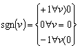 | (3) |
2.3. Viscous Friction Model
A viscous friction occurs in the cases when there is an oil between the contact surfaces, which reduces friction coefficient f. This coefficient is lower than Coulomb friction coefficient fC. Viscous friction is represented as a linear function of velocity | (4) |
2.4. Stribeck Effect
A Stribeck effect is a kind of friction which occurs when a liquid or solid oils is used for the contact surfaces of moving mechanical parts. This causes decreasing of friction F with an increasing velocity v until to so-called Stribeck velocity vs. From this velocity starts affect especially viscous friction. A Stribeck effect is a function of used oil. Stribeck curve is a continuous drop in the friction force for small velocities, which originates from the transition of boundary lubrication to full fluid lubrication through partial fluid lubrication.The stribeck effect can be described as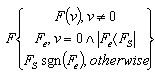 | (5) |
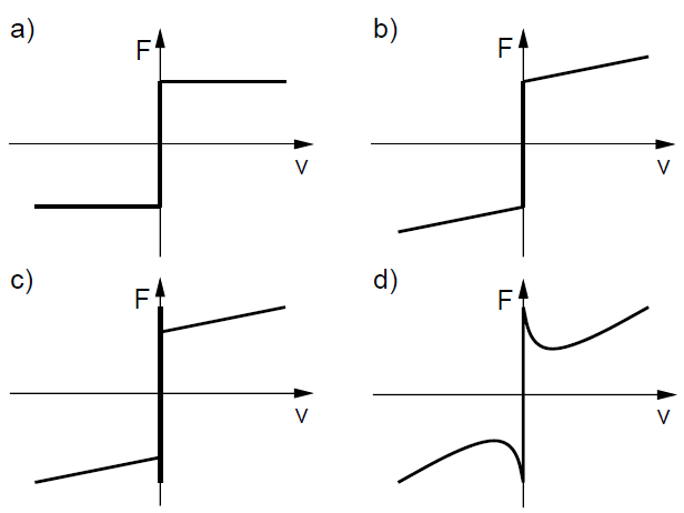 | Figure 1. Different kinds of friction models |
There are different ways to describe F(v) but the most common form of the nonlinearity is 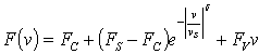 | (6) |
Where vs is called the Stribeck velocity.
3. DC Motor
A common actuator in control systems is the DC motor. The Figure 2 presents simplified electrical circuit of DC motor and mechanical model of a rotor.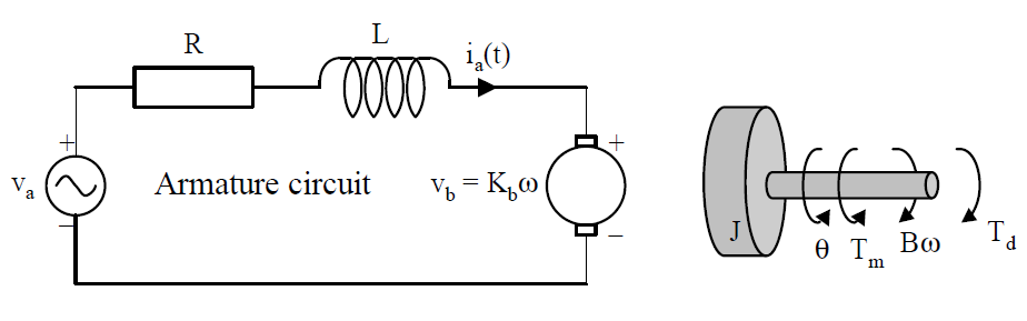 | Figure 2. DC motor |
For the armature of DC motor, we will use the following parameters values:R=armature resistance=10 ΩL=armature inductance=0.0013 HJ=moment of motor inertia=2.54e-6 kgm2Km=motor torque constant=0.039 Nm/AKb=back emf constant=0.039 Vrad/sB=viscous friction (will be identified by experiment)Tm=motor torqueFor DC motor can be written following equations.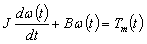 | (7) |
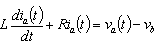 | (8) |
 | (9) |
 | (10) |
After Laplace transformation we can obtain transfer function of DC motor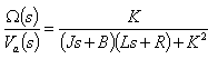 | (11) |
Where K=Km=Kb. The model of DC motor can be expressed by block diagram as well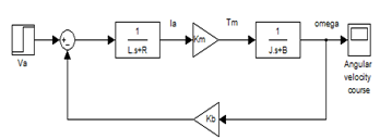 | Figure 3. Dc motor block diagram |
In the next section friction of the DC motor will be identified and subsequently DC motor mathematical model can be simulated and compared with real DC motor behavior.
4. Experiment, simulation and results
The principle of experimental friction identification results from first Newton´s law of motion.[6] Motion of DC motor can be described by equation (12)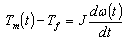 | (12) |
Where Tf is a friction torque. When angular velocity ω(t)is constant then we obtain equation (13) | (13) |
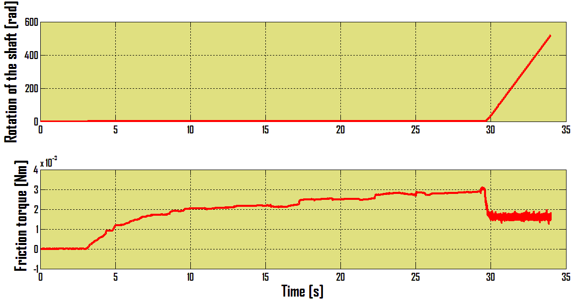
Now our task is measuring of motor torque Tm what is not difficult task. For this purpose we use software Matlab / Simulink – Real Time toolbox and measuring card MF624. By means of MF624 we will measure voltage variation on a resistor and by Simulink we can get current fluctuation. From obtained current fluctuation course by means of equation (10) we get motor torque course what is according equation (13) motor friction torque course.The angular velocity is measured by incremental encoder IRC 245 / 1000 which is part of investigated DC motor. The output signal from encoder is by MF624 processed.The example of measured friction torque is on the Figure 4.As can be seen, from 0,5 sec the angular velocity of DC motor is constant and from this time is friction torque measured.The friction torque was measured for fifteen different constant angular velocities. After this measuring the next task is static friction torque determination. On the Figure 5 the static friction torque course is shown.From the Figure 5 is obvious that friction torque decrease when DC motor output shaft starts rotate. From performed measurements it can be state a DC motor friction course which is on Figure 6 shown.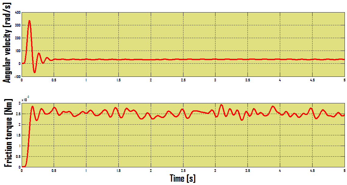 | Figure 4. Friction torque course for constant angular velocity |
 | Figure 5. The static friction torque course |
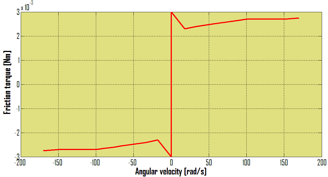 | Figure 6. DC motor friction torque course |
On the Figure 6 can be seen Stribeck effect which can be partly visible from the Figure 5 as well. Now the mathematical model of DC motor can be compared with real DC motor behavior. The simulation is compared with experiment by Matlab / Simulink.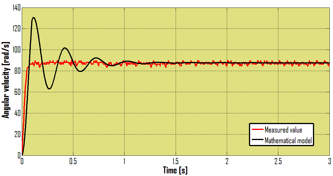 | Figure 7. The mathematical model compared with real DC motor |
For mathematical model was Coulomb friction model used. Because of this there are differences between mathematical model simulation and experiment result as can be seen on the Figure 6. Our goal was investigate only steady state therefore for simulation was used concrete value of friction which occurs for defined angular velocity.
5. Conclusions
The paper deals with experimental method of friction identification. In the paper basic friction models and DC motor mathematical model are presented. The purpose of the paper is DC motor friction torque determination and verification with mathematical model is steady state. The principle of friction identification is the measuring of motor torque while motor has constant angular velocity. In this case motor torque equals friction torque. The resultant friction torque course is identical with Stribeck effect. This method is very simple and undemanding. It requires only angular velocity sensor and recording equipment as for example measuring card in conjuction with Matlab/ Simulink. For concrete DC motor application it should be friction identified and then the control strategy chosen.
ACKNOWLEDGEMENTS
The authors would like to thank to Slovak Grant Agency – project VEGA 1/1205/12 "Numerical modelling of mechatronic systems". This contribution is also the result of the grant project of Tatra Bank – “LOCOSNAKE” – robotic mechanisms motion with steering software support. This contribution is also result of the project APVV-0091-11 “Using of methods of experimental and numerical modelling for increasing of competitiveness and innovation of mechanical and mechatronical systems”.
References
| [1] | H. Olsson, K. J. Åström, C. Canudas de Wit, M. Gäfvert, P. Lischinsky, “Friction models and friction compensation”, European journal of control, No. 4, pp. 176-195, December 1998. |
| [2] | B. Amstrong, “Stick slip and control in low-speed motion”, IEEE transaction on automatic control, vol. 38, No. 10, 1993. |
| [3] | C. Iurian, F. Ikhouane, J. Rodellar, R. Grinó, “Identification of a system with dry friction”, University of Barcelona, September 2005. |
| [4] | D. Zardecki, “Picewise linear modeling of friction and stick-slip phenomenon in discrete dynamical systems”, Journal of theoretical and applied mechanics, pp. 255-277, Warsaw 2006. |
| [5] | Y. F. Wang, D. H. Wang, T. Y. Chai, “Modeling and control compensation of nonlinear friction using adaptive fuzzy systems”, Mechanical systems and signal processing 23, ISSN 2445-2457, 2009. |
| [6] | I. Virgala, “A mechatronic approach to design systems imitating snake locomotion in limited area”, PhD thesis, Technical university of Košice, 2012. |
| [7] | H. Henrichfreise, “Prototyping of a LQG Compensator for a Compliant Positioning System With Friction”, HNI – Verlagsschriftenreihe, Vol. 23, 1997. |
 Abstract
 Reference
 Full-Text PDF
 Full-text HTML