Konstantinos S. Papachristou , Dimitrios S. Sophianopoulos
Departmentof Civil Engineering, University of Thessaly, Volos, 38334, Greece
Correspondence to: Dimitrios S. Sophianopoulos , Departmentof Civil Engineering, University of Thessaly, Volos, 38334, Greece.
| Email: |  |
Copyright © 2012 Scientific & Academic Publishing. All Rights Reserved.
Abstract
The buckling of axially compressed beams resting on elastic foundation is considered, accounting for discontinuous (unbonded) contact between beam and subgrade which is the case of real structural response. Using Galerkin’s method a two-region contact/non-contact configuration was revealed as the only possible post-buckling deformation for both pinned – pinned and fixed – fixed boundary conditions, a fact strongly contradicting relevant results where continuous contact was assumed.
Keywords:
Buckling, Elastic Foundation, Discontinuous Contact, Galerkin’s Method
Cite this paper: Konstantinos S. Papachristou , Dimitrios S. Sophianopoulos , Buckling of Beams on Elastic Foundation Considering Discontinuous (Unbonded) Contact, International Journal of Mechanics and Applications, Vol. 3 No. 1, 2013, pp. 4-12. doi: 10.5923/j.mechanics.20130301.02.
1. Introductory Remarks
The contents of the overwhelming majority of publications on the buckling of beams resting on various elastic foundation types, are based on the assumption that there is a full (continuous) contact between beam and subgrade, i.e. that the latter reacts opposite to the resulting flexural deflection, regardless of its sign. However, for real applications, the soil can only react when in pressure from the beam, which may be caused by either the action of a transverse load along the span[1] or bending moments at the supports, or by the beam itself due to buckling deformation (combination of both actions not excluded). For the former type of action, only a limited number of relevant studies have been published, each tackling the problem via different approaches. One should quote the work by Cakiroglu and Cakiroglu[2], where continuous and discontinuous contact problems for strips on an elastic semi-infinite plane were investigated via Fourier transformations and use of Navier equations. In this work, the wide applicability of the discontinuous contact problem was emphasized, ranging from railway ballast, foundation grillages and continuous foundation beams to runways, liquid tanks resting on the ground and grain silos. Kerr, in an earlier work[3], considered the unbonded contact between elastic and elastic-rigid media and specifically the indentation of an elastic half-space by a rigid circular cylinder and a rigid sphere as well as the unbonded contact between a plate and an elastic half-space, using an essentially energy approach. More recently[4] the problem of tensionless contact of a finite beam resting on Reissner foundation, acted upon by a point load and considering discontinuous contact was analysed, accounting for boundary and matching conditions, while a similar problem (contact of beams resting on tensionless two-parameter foundations) was also dealt with[5]. Two totally different formulations were adopted for the problem of structural elements in unilateral contact with an elastic foundation[6]. Namely, the contact problem was formulated either as a constrained optimization one by using the Finite Element Method for discretising the structure and the elastic foundation, or by employing the Ritz method. The whole problem was finally treated as an unconstrained optimum design one, but the cases of contact loss dealt with, depicted in Figure 1, did not include the action of axial compression of the structure resting on elastic foundation.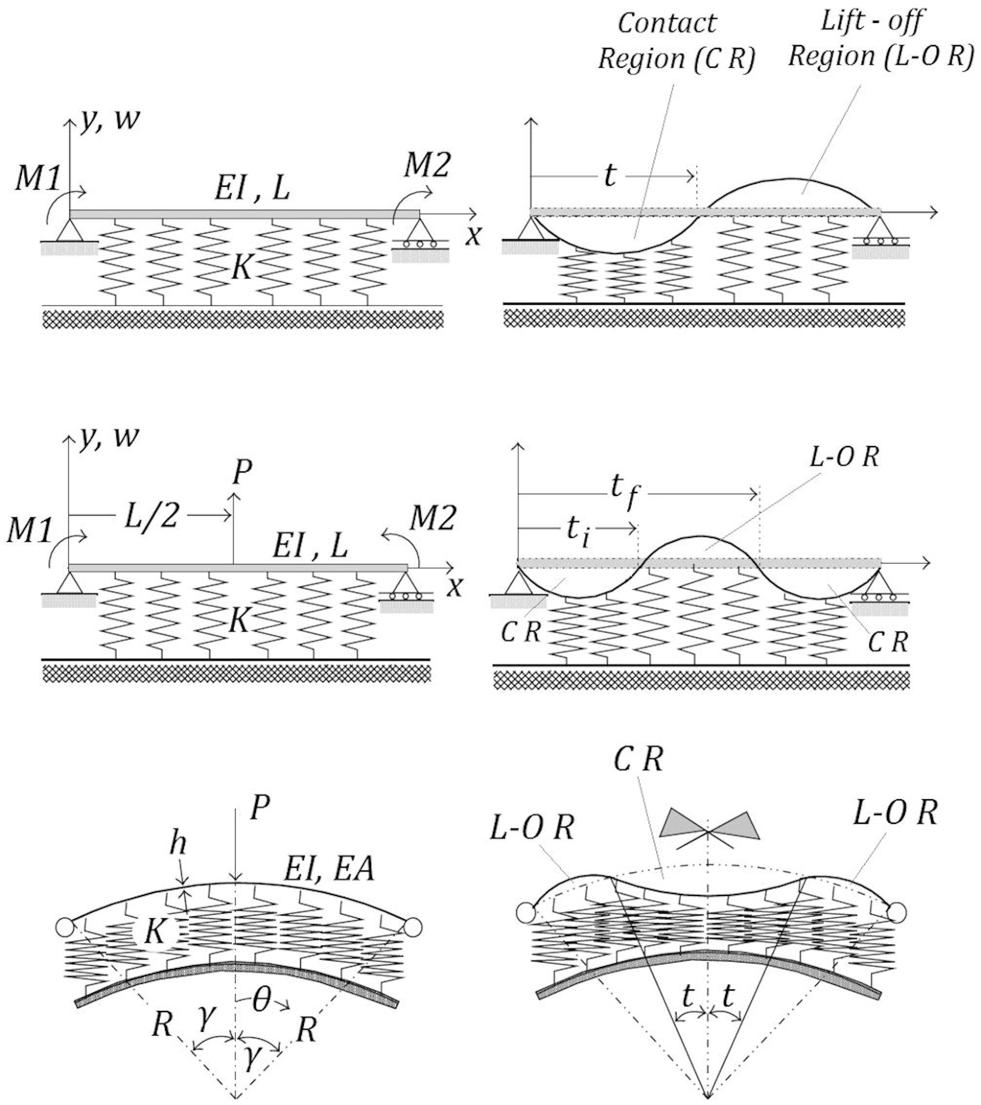 | Figure 1. Structural elements under unilateral contact constraints and corresponding deformation patterns (from Silveira et al. 2008) |
Although the aforementioned publications contain valuable information about the unbonded contact between beam and foundation, none of them considers axial compression individually or combined simultaneously with other types of loading.On the other hand, an already buckled beam, whose lateral deformation is constrained by a flexible surface which is flat before deformation, and is acted upon by a point transverse load, constitutes a significant mechanics problem, arising for instance when a vehicle travels on a blown-up highway pavement caused by temperature elevation[7]. Under such circumstances it was found that the corresponding static deformations may follow five significant patterns: non-contact, full-contact, one-sided contact, two-sided contact and isolated contact in the middle. These are shown in Figure 2, where L refers to the presence of the point load in the left half of the beam, while R for its presence in the right half of the beam.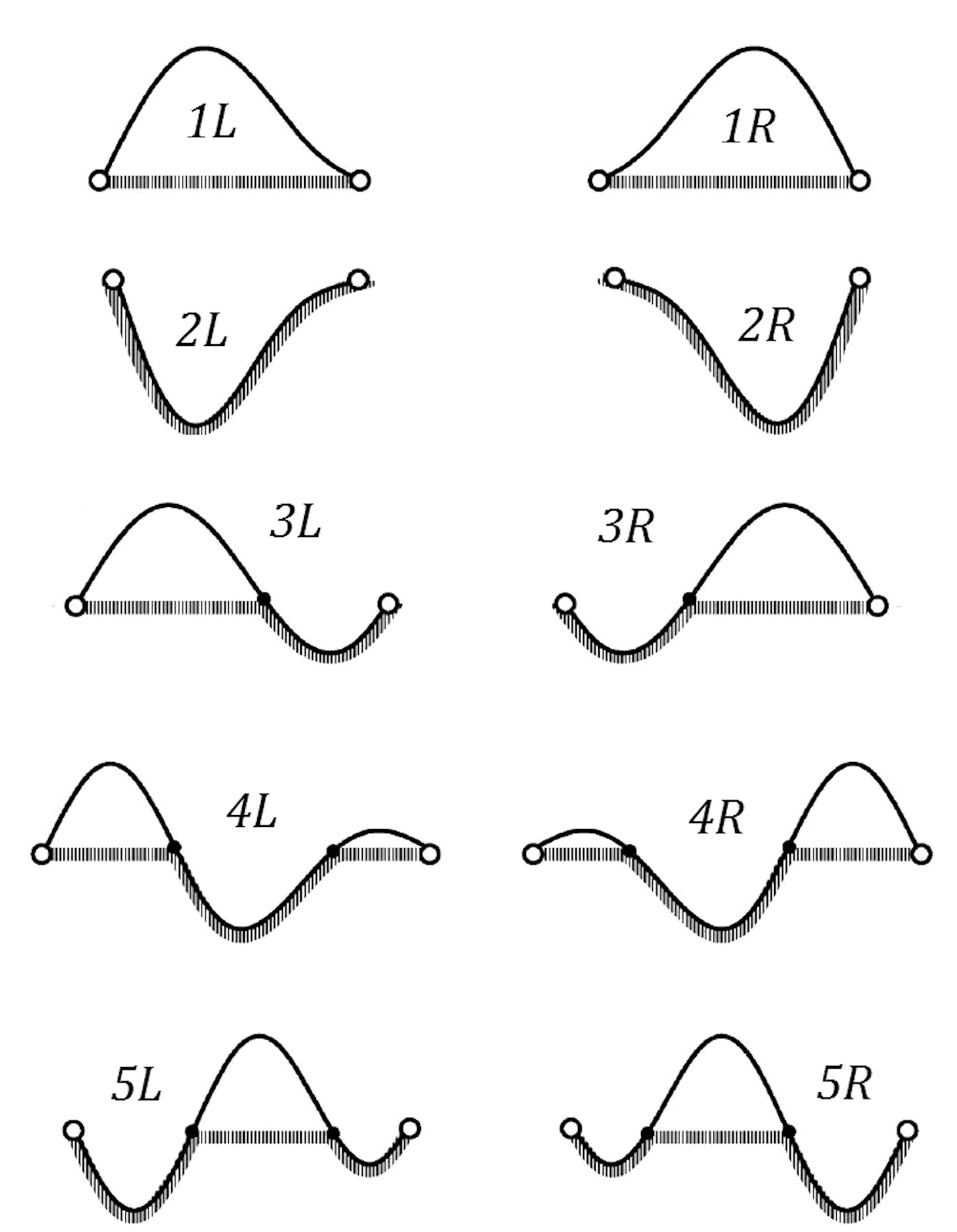 | Figure 2. Five deformation patterns (from Chen and Wu 2011) |
These patterns however are strictly dependent on the position of the point load, while the buckling – contact problem, which leads to the a priori assumption of the so-called buckled beam, is not considered. Intuitively, the authors adopted two regions for the buckled beam, one in contact and one in no contact, before the point load starts acting.The only pertinent contribution, combining the simultaneous action of axial and transverse loading on a homogeneous pinned – pinned beam on a Winkler type nonlinear, viscoelastic and unilateral foundation is the one by Bhattiprolu et al.[8]. The corresponding schematic (with non-dimensionless variables) is shown in Figure 3, from where it can be readily perceived that the region in contact depends mainly on the position of the transverse point load along the span.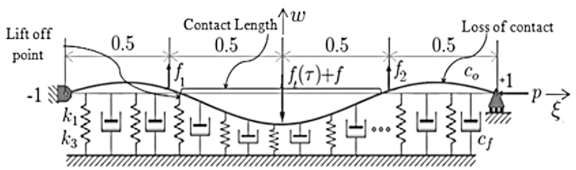 | Figure 3. Schematic of pinned – pinned beam on a nonlinear (unilateral) viscoelastic foundation (from Bhattiprolu et al. 2011) |
Defining in general by Ff (w) the force exerted by the foundation (active only within the contact region, that is subgrade reacting only in compression) and slightly altering the above notation, by considering the origin at the left support of the beam (i.e.ξ ranging from 0 to 1) and the flexural deflection w(ξ) facing downwards, the dimensionless form of the buckling equation may be written as follows: | (1) |
where the subscript denotes differentiation with respect to ξ, and H(ξ) is an auxiliary contact function defined as | (2) |
Equations (1) and (2) accompanied by the boundary conditions at the supports constitute a very complicated two-point boundary value problem, which may solved only numerically.
2. Problem Statement and Mathematical Formulation
We consider an elastically supported, Euler-Bernoulli axially compressed beam of uniform cross-section, which rests on a subgrade modelled as an elastic foundation, with the unique characteristic that the latter only reacts when the beam’s flexural deflection (at the instance of buckling ) is directed towards it. In general terms, this implies that there exists an unbonded (discontinuous) contact between beam and foundation, characterized by successive contact and non-contact regions along the length of the beam. When buckling occurs, i.e. when the beam equilibrates in an arbitrary deformed shape, we assume that there are totally i regions of the beam, from which some are in contact with the foundation and the rest are not. Since every contact region must be followed by a non-contact one and vise-versa, and excluding the case of i =1 (full or no contact), two significant deformed configurations must be considered. The first one is associated with equal (even) number of such regions, denoted by c and n respectively for which it is valid thatc = n = i /2.This configuration should be divided into two subcases, depending on the nature of the 1st region, i.e. on whether this is in contact or not. On the other hand, the second configuration, for which odd regions of contact and no contact exist, should also be divided into two sub-cases, depending on whether one more or one less contact region appears, a fact dictated by the nature of the 1st region, as above. If this is in contact, then also the last region is in contact and consequentlyc=n+1 ↔ c=(i + 1 ) / 2, n = (i-1)/2. In the same manner, if the 1st region is not in contact, the same stands for the last one and hencec = n - 1 ↔ c = (i -1)/2, n = ( i + 1 ) / 2.If L is the distance between the supports of the beam, which thereafter will be considered immovable, then the length of each region is denoted by αjL , j = 1,2,…i, where αj are positive real coefficients to be determined; obviouslyL = Σij=1αj, while at the points where contact is lost the flexural deflection equals to zero. The two main possible buckled shapes of the beam (with their divisions) along with the corresponding sign convention are depicted in Figures 4 and 5.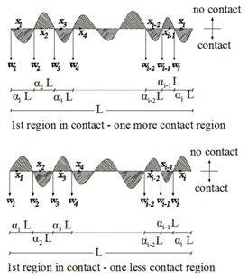 | Figure 4. Buckled beam with odd regions in contact |
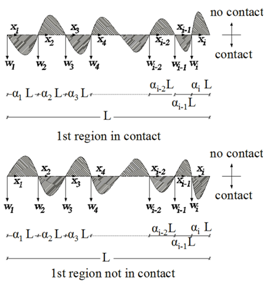 | Figure 5. Buckled beam with even regions in contact |
Hence, the beam consists ofi sub-beams / regions, whose dimensionless flexural deflection is denoted by wi(xi). Those not in contact, n in number, obey the differential operator associated with the well-known buckling equation of an elastically supported beam without transverse loading, given by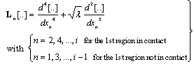 | (3a) |
where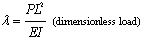 | (3b) |
On the other hand, the c in number sub-beams in contact, satisfy the differential operator associated with the buckling of an elastically supported beam resting on an elastic foundation, considering continuous contact; the form of this particular differential operator, denoted by Lc[..], depends on the nature – model of the foundation. For instance, if one adopts the Pasternak or the Wieghardt model, then one may write that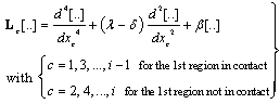 | (4a) |
where, for the Pasternak model,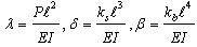 | (4b) |
while, for the Wieghardt model[10,11],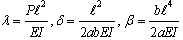 | (4c) |
In expressions (4b) and (4c)ks, kb, α and b are constants depending on the properties of the elastic foundation.Evidently, there are four (4) boundary conditions (two at each support of the beam), 2( i - 1) zero deflection conditions at the points of contact loss, as well as 3( i – 1) continuity (matching) conditions at these points, namely i -1 rotation equalities, i -1 bending moment equilibria and i -1 shear force equlibria. Thus, the total amount of available conditions is 5( i – 4)+4 = 5 i -1. The unknowns are the functions describing the deformed shapes of the sub-beams (i -1 in number), their lengths (namely the values of aj, j=1,2,..i-1) and the value of the critical load. This constitutes a well posed Boundary Value Problem in Structural Mechanics[12,13].
3. Proposed Solution Technique
We assume that the dimensionless flexural deflection of each sub-beam is approximated by a fourth order polynomial (basis function) of the form | (5) |
satisfying all the boundary and matching conditions described earlier. Evidently coefficients Ai, Bi, Γi, Δi, Ei are linearly dependent, so one may arbitrarily chose the value of one of them, for instance A1=1, without any loss of generality. Applying the 5i-1 conditions will lead to a linear inhomogeneous system of order 5i-1, which may be solved symbolically and produce expressions for the coefficients that are in general nonlinear functions of the yet unknown aj, j=1,2,..i-1.The next task is to apply the flat version of Galerkin’s method[14] for each sub-beam, with the appropriate choice of the differential operators given above. In doing this, we demand that in general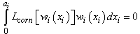 | (6) |
The product of each of the above will be an algebraic equation with respect to λ, readily solvable. Hence, the i equations (6) will produce i expressions for λ, each being a nonlinear function of αi, but representing the same load, i.e. the buckling load. Thus, we arrive at a system of i-1 nonlinear algebraic equations with respect to αj, j=1,2,…,i-1. This, if solved, may produce various sets of values for αj. The acceptable ones must all have positive values smaller than 1 and their sum must also be smaller than 1. Furthermore, the resulting approximate shape functions should have the shape illustrated in Figure 4, implying that the remaining two roots of each basis function (except x = 0 and x = ai) must either be imaginary or real not belonging to the interval 0 < x < ai. In other words, and since the 4th order polynomial representing each wi (xi) may be written in the form, | (7) |
each second order polynomialf (xi) should either have a negative discriminant or have real roots outside[0, αi]. One may perform symbolic manipulations – in order to check the above – for any value of i, starting with i = 2. At this point, and given the physical problem approximated, it should be noted that a configuration containing more than two regions is not likely to occur, since there is no transverse loading present to force a contact region; from a pure energy point of view, if contact is lost, then the portion of the beam not in contact will buckle with the easiest available way, i.e. in a single “waveform” type. Obviously, every contact region will always buckle in the same manner, by definition. Hence, it is conjectured that only the simplest case of contact (i = 2) will produce acceptable results.Thus, one assumes only two regions, one in contact and one not and proceeds in solving the problem twice, by considering 1st region in contact and not in contact. The configuration associated with the lowest buckling load will be the solution of the problem.
4. Numerical Results and Discussion
The above scheme is applied for the steel beam - column and subgrade parameters, that correspond to real structure situations and especially on welded railway tracks. More specifically three (3) beamtypes were considered with properties contained in Table 1, reproduced from[9]; these were combined with three (3) soil types with characteristics given in Table 2.| Table 1. Cross-sectional properties of the steel beam-columns considered |
| | Beam Type | Description | A(cm2) | I(cm4) | ℓ(cm) | λ (slenderness) | | BT1 | 25 lb ASCE Rail | 15.48 | 104.06 | 1000 | 385.7 | | BT2 | 115 lb AREA Rail | 72.65 | 2730.48 | 1000 | 163.1 | | BT3 | HEB 450 | 218.00 | 79890.00 | 700 | 36.6 |
|
|
| Table 2. The three (3) soil types and their properties considered |
| | Soil Type | Description | E (MPa) | ν | G (MPa) | | ST1 | Gravel | 20 | 0.33 | 7.50 | | ST2 | Sand Gravel | 125 | 0.30 | 48.10 | | ST3 | Soft Clay | 10 | 0.30 | 3.85 |
|
|
According to the above, six (6) specific beam-subgrade combinations (Cases), given in Table 3, were used for obtaining numerical results.| Table 3. Beam-subgrade Cases considered |
| | Cases considered | β | δ | | BT1 + ST1 | 915751 | 2404 | | BT1 + ST2 | 5723443 | 15410 | | BT2 + ST1 | 34886 | 183.2 | | BT2 + ST2 | 218036 | 1174.1 | | BT3 +ST2 | 1789 | 29.5 | | BT3 + ST3 | 143.1 | 2.4 |
|
|
4.1. Pinned – Pinned Beam - Columns
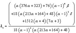
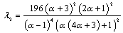
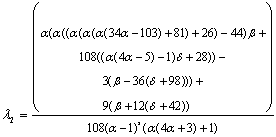
For this case, the application of the conditions for the two-region assumption and since only the length of the 1st region is sought, say equal to α, leads to the following values of the coefficients Ai, Bi, Γi, Δi, Ei , i = 1,2 of the approximate shape functions, obtained symbolically[14]: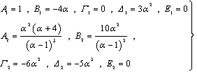 | (8) |
If the 1st region is in contact, Galerkin’s method yields the following expressions for the buckling loads at each region: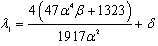 | (9a) |
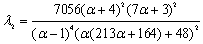 | (9b) |
If the 1st region is not in contact, the corresponding expressions are: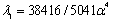 | (10a) |
 | (10b) |
Demanding λ1= λ2 and adopting specific beam-foundation parameters and notation the values of α and the corresponding critical (buckling) loads are given in Table 4.| Table 4. Results of the proposed scheme for a pinned – pinned beam |
| | Case | α | λcr | Full contact lowest buckling load* | | 1st region in contact | 1st region not in contact | 1st region in contact | 1st region not in contact | | BT1+ST1 | 0.785268 | 0.101555 | 57788 | 71646.2 | 95198.8 | | BT1+ST2 | 0.874244 | 0.0632278 | 444415 | 476830 | 595326 | | BT2+ST1 | 0.090768 | 0.243622 | 546.455 | 2163.38 | 3727.76 | | BT2+ST2 | 0.657052 | 0.147001 | 10411.8 | 16320 | 23275.6 | | BT3+ST2 | 0.0746828 | 0.493842 | 525.423 | 128.13 | 220.633 | | BT3+ST3 | 0.0728198 | 0.567716 | 523.069 | 73.362 | 26.7687 | | *obtained numerically from the corresponding buckling equation contained in[9] |
|
|
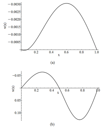
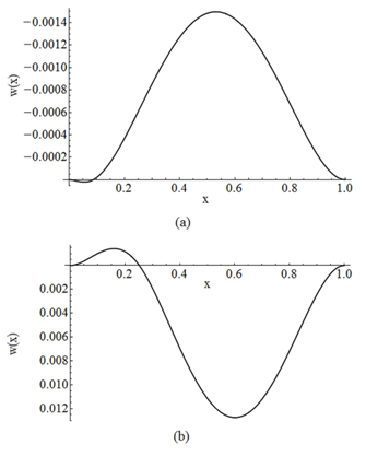
The buckled beam – column configurations corresponding to the Cases described in the above Table are represented graphically throughout Figures 6 – 11.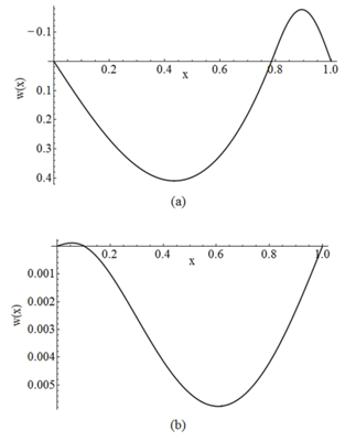 | Figure 6. Buckled configuration of a hinged – hinged beam for Case BT1+ST1 for the first region (a) in contact and, (b) not in contact |
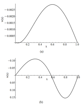
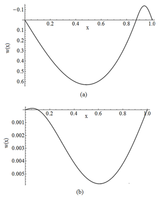 | Figure 7. Buckled configuration of a hinged – hinged beam for Case BT1+ST2 for the first region (a) in contact and, (b) not in contact |
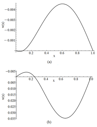 | Figure 8. Buckled configuration of a hinged – hinged beam for Case BT2+ST1 for the first region (a) in contact and, (b) not in contact |
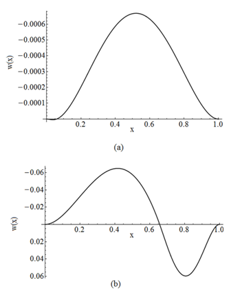
 | Figure 10. Buckled configuration of a hinged – hinged beam for Case BT3+ST2 for the first region (a) in contact and, (b) not in contact |
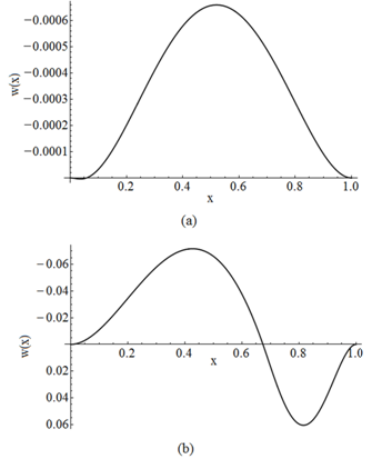
 | Figure 11. Buckled configuration of a hinged – hinged beam for Case BT3+ST3 for the first region (a) in contact and, (b) not in contact |
4.2. Fixed – Fixed Beam – Columns
Similarly[14], the outcome of the evaluation procedure for the coefficients of the basis functions is: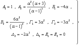 | (11) |
For the 1st region considered in contact we get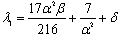 | (12a) |
 | (12b) |
while, for the 1st region not in contact, it is found that | (13a) |
 | (13b) |
For λ1 = λ2 and the same as above beam – column Cases, the results obtained are shown in Table 5. The value of the critical load for full contact is obtained numerically from the corresponding buckling equation, given in[9].| Table 5. Results of the proposed scheme for a fixed – fixed beam |
| | Case | α | λcr | Full contact lowest buckling load | | 1st region in contact | 1st region not in contact | 1st region in contact | 1st region not in contact | | BT1+ST1 | 0.610356 | 0.170145 | 29272.5 | 58468.2 | 4356.58 | | BT1+ST2 | 0.793653 | 0.104103 | 299157 | 417194 | 20347.5 | | BT2+ST1 | 0.0610332 | 0.445488 | 2072.6 | 1244.09 | 591.164 | | BT2+ST2 | 0.0872815 | 0.251825 | 2223.7 | 12184.2 | 2273.58 | | BT3+ST2 | 0.0587228 | 0.657117 | 2059.93 | 262.8 | 146.479 | | BT3+ST3 | 0.0583567 | 0.672675 | 2057.93 | 238.05 | 52.6051 |
|
|
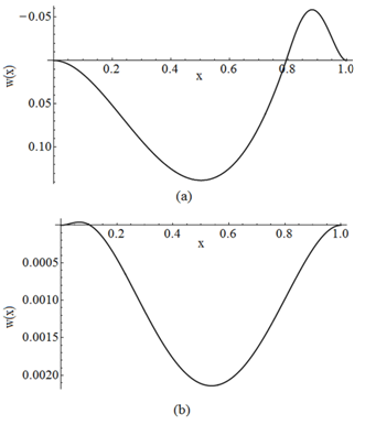
The graphic representation of these results is given in Figures 12 – 17.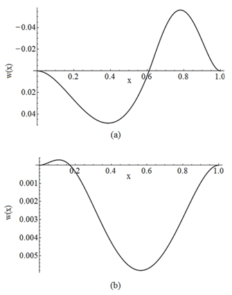 | Figure 12. Buckled configuration of a fixed – fixed beam for Case BT1+ST1 for the first region (a) in contact and, (b) not in contact |
 | Figure 13. Buckled configuration of a fixed – fixed beam for Case BT1+ST2 for the first region (a) in contact and, (b) not in contact |
 | Figure 15. Buckled configuration of a fixed – fixed beam for Case BT2+ST2 for the first region (a) in contact and, (b) not in contact |
 | Figure 16. Buckled configuration of a fixed – fixed beam for Case BT3+ST2 for the first region (a) in contact and, (b) not in contact |
 | Figure 17. Buckled configuration of a fixed – fixed beam for Case BT3+ST3 for the first region (a) in contact and, (b) not in contact |
As mentioned in the Introduction, there is an important lack of published theoretical works related to the problem studied herein and a total absence of experimental evidence. From a purely qualitative view point, the results obtained in this investigation, concerning only two regions in the buckling beam configuration (one in contact with the subgrade) are in full accordance with the finding reported in [8]. Moreover, from filed observations of the thermal buckling phenomenon of buckling of railway tracks in the vertical plane, reported in[15,16], similar behaviour was exhibited.The above remarks constitute an initial validation of the proposed scheme, which should be further enhanced by experiments and additional analyses, not yet reported in the literature.
5. Conclusions
Soil type 1 (ST1) represents a moderately stiff foundation made of gravel, ST2 a very stiff subgrade of sand gravel, while ST3 a flexible soft clay soil. In parallel, beam type 1 (BT1) is very slender and of rather small flexural rigidity, BT2 is also very slender (but not as slender as BT1) and of moderate EI, while BT3 is very rigid and non-slender. Accounting for the above remarks and the physical problem in view, the results obtained via the proposed approximate scheme are reasonable and to a large extent expected.More specifically, the absence of rotational restraints at the supports for the pinned – pinned beam, allows a smooth interaction between beam and subgrade, and this is the main reason that all critical situations (except when BT3 is used, which is a rather extreme choice) appear with the first region of the beam in contact with the foundation. Moreover, all critical buckling loads evaluated, excluding the unrealistic combination ST3+BT3, are smaller than the corresponding ones related with full contact. This important finding implies that the assumption of full contact in the simulations is not on the safe side, at least for the foundation model adopted herein. More work is due, accounting for other foundation models, in order to generalize this finding, as related to real applications.On the other hand, for the fixed – fixed beam, the full rotational restraint at the supports either accentuates contact or prohibits it, depending on the stiffness of beam and foundation and the slenderness of the beam. From the results obtained, the critical loads related with unbonded contact, are always greater (to a larger or smaller scales) than the ones with full contact considered. This finding is in strict conformity with the well accepted principle of elastic stability, dictating that the buckling loads depend on the boundary conditions and not on the transverse loading. Note that regardless of full or unbonded contact assumed, the contact itself is a transverse loading.The results obtained by this method, in order to be fully validated, requires experimental evidence and not calibration with finite element simulations, since the Galerkin method adopted is the basis of FE, a fact that cannot be controverted.
References
| [1] | H D Conway and K A Farnham, “Bending of a Finite Beam in Bonded and Unbonded Contact with an Elastic Foundation”, International Journal of Mechanical Sciences, vol.12, pp.997-1055, 1970. |
| [2] | Osman A Çakiroğlu and Fenzli L Çakiroğlu, “Continuous and Discontinuous Contact Problems for Strips on an Elastic Semi-Infinite Plane”, International Journal of Engineering Science, vol. 29, n0.1, pp.99 -111, 1991. |
| [3] | Arnold D Kerr, “On the Unbonded Contact between Elastic and Elastic-Rigid Media”, Acta Mechanica, vol.33, nos.1-2, pp.135-146, 1979. |
| [4] | Yin Zhang, “Tensionless contact of a finite beam resting on Reissner foundation”, International Journal of Mechanical Sciences, vol.50, no.6, pp.1035-1041, 2008. |
| [5] | Andrea Nobili, Luca Lanzoni, “On the contact problem of beams resting on tensionless two-parameter foundations”, in Proceedings of the XX AMIETA Congress, Bolognia, Italy, 12 – 15 September, 2011. |
| [6] | Ricardo AM Silveira, Wellington LA Pereira and Paulo B Gonçalves, “Constrained and Unconstrained Optimization Formulations for Structural Element in Unilateral Contact with an Elastic Foundation”, Mathematical Problems in Engineering, Volume 2008, Article ID 786520. |
| [7] | Jen-San Chen and Hsu-Hao Wu, “Response of a Buckled Beam Constrained by a Tensionless Elastic Foundation”, Journal of Engineering Mechanics (ASCE), vol.137, no.6, pp.383-389, 2011. |
| [8] | Udbhau Bhattiprolu, Anil Bajaj and Patricia Davis, “Response of a beam on anon-linear tensionless viscoelastic foundation”, in Proceedings of ENOC 2011 7th European Nonlinear Dynamics Conference, Rome, Italy, 24 – 29 July 2011. |
| [9] | Dimitrios S Sophianopoulos and Konstantinos S Papachristou, “In-plane stability of uniform steel beam – columns on a Pasternak foundation with zero end-shortening”, Archive of Applied Mechanics, vol.82, nos.10-11, pp. 1653-1662, Special Issue, 2012. |
| [10] | T E Smith, “Buckling of a Beam on a Wieghardt-Type Elastic Foundation”, Zeitschrift für Angewandte Mathematik und Mechanik, vol.49, no.11, pp.641-645, 1969. |
| [11] | Guiseppe C Rutta and Isaac Elishakoff, “Buckling of a Column on a Wieghardt foundation”, Zeitschrift für Angewandte Mathematik und Mechanik, vol.86, no.8, pp.617-627, 2006. |
| [12] | Arnold D Kerr “On the Derivation of Well Posed Boundary Value Problems in Structural Mechanics”, International Journal of Solids and Structures, vol.12, no.1, pp.1-11, 1976. |
| [13] | Herbert B Keller, Numerical Methods for Two-Point Boundary Value Problems, Blaisdell, 1999. |
| [14] | Thomas B Bahder, Mathematica for Scientists and Engineers, Addison – Wesley, 1994 |
| [15] | Arnold D Kerr, “A Model Study for Vertical Track Buckling”, High Speed Ground Transportation Journal, vol.7, pp. 351-368, 1973. |
| [16] | Arnold D Kerr and Y M El-Aini, “Determination of Admissible Temperature Increases to Prevent Vertical Track Buckling”, Journal of Applied Mechanics (ASME), vol.45, no.3, pp. 565-573, 1978. |
 Abstract
 Reference
 Full-Text PDF
 Full-text HTML