Chigbogu G. Ozoegwu 1, Chigozie F. Uzoh 2, Jeremiah L. Chukwuneke 1, Paul C. Okolie 1
1Department of Mechanical Engineering, Nnamdi Azikiwe University, Awka, PMB 5025, Nigeria
2Department of Chemical Engineering, Nnamdi Azikiwe University, Awka, PMB 5025, Nigeria
Correspondence to: Chigbogu G. Ozoegwu , Department of Mechanical Engineering, Nnamdi Azikiwe University, Awka, PMB 5025, Nigeria.
| Email: |  |
Copyright © 2012 Scientific & Academic Publishing. All Rights Reserved.
Abstract
It was noticed in laboratory practice that certain conditions of slotting operation of a plastic end milling computer Numerical control (CNC) machine became noisy with increasing depth of cut and eventual perforation of workpiece thus objective is to generate stability characterization of the machine in the form of a chart on the plane of cutting parameters on which stable operation is demarcated from the unstable operation. Chatter stability analysis is carried out here using a recently developed method called Full-discretization. The resulting chart is partitioned into portions of secondary Hopf and flip bifurcations through MATLAB eigen-value analysis of resulting monodromy operator. These two types of bifurcation are discovered to be visible for high speed range while only secondary Hopf bifurcation is visible for the low spindle speed range. It is also discovered for the studied slotting operation, that critical characteristic multipliers are almost pure imaginary at the turning points of secondary Hopf bifurcation lobes and get closer to the negative real axis when critical points move away from minimum points. Equation describing the infinitely many but discrete secondary Hopf bifurcation chatter frequencies at minimum points is postulated. The parameters of the end milling process are; tool mass m=0.0431kg tool natural frequency 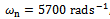 damping factor
  and workpiece cutting coefficient
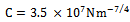 . The stability chart generated for the system shows close agreement with both practice and theory.
Keywords:
Chatter, Stability lobe, Minimum points, Full-discretization, Secondary Hopf bifurcation, Flip bifurcation
Cite this paper:
Chigbogu C. Ozoegwu , Chigozie F. Uzoh , Jeremiah L. Chukwuneke , Paul C. Okolie , "Chatter Stability Characterization of a Three-Flute End-Miller Using the Method of Full-Discretization", International Journal of Mechanics and Applications, Vol. 2 No. 6, 2012, pp. 143-151. doi: 10.5923/j.mechanics.20120206.07.
1. Introduction
Components of high dimensional integrity are in ever increasing need. Machine tools such as Lathe and Milling machines are needed for production of such components. They would not perform effectively under highly disturbed situations thus the need for vibration control in such machines. Achieving good surface finish and high productivity are two opposed demands in machining operation. This means that ascertaining safe operation range for good product, improved tool life and design of machine tools is necessary.A typical machining process of major importance is the end-milling in which a machined surface that is at right angle with the cutter axis results as shown Figure1. End milling cutters equipped with shanks for mounting on the spindle are utilized for end milling. Unstable regenerative machine tool vibration is basically called chatter. Chatter invariably results whenever there is dynamic interaction between the tool and the workpiece of a milling process under unstable cutting parameter combination. Forced, self-exited and damped natural vibrations combine to compound the dynamics of milling process. The forced vibration component is driven by a periodic force stemming from regular engagement and dis-engagement of tool and workpiece. Regenerative effect is underpinned as the major cause of the self-exited vibrations (mechanical chatter) in machining[1]. Regenerative effect is a concept used to explain the sustained vibration occurring during machining as resulting from cutting force variation due to vibration induced surface waviness. Arnold first suggested regenerative effects as the potential cause of chatter and is now arguably considered the cause of the most detrimental type of machine tool vibration[2]. 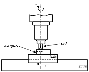 | Figure 1. End-milling |
Effects of periodic chip thickness and delayed position on the present position of the tool result in periodic delay differential equations model for regenerative vibrations of milling. Among the various advanced methods utilized in tracking the approximate stability transition curve of regenerative milling are; the finite element in time[3, 4], Chebyshev Polynomials[4, 5], semi-discretization[6], Fargue-type approximation[7, 8]. The normal procedure is generation of finite dimensional discrete approximation of infinite dimensional periodic delay differential equation of regenerative milling process and carrying out eigen-value analysis of resulting finite monodromy operator as cutting parameters vary.A recently developed method called Full-discretization[9] is utilized for model transformation in this work. Eigen-value analysis of resulting finite dimensional monodromy operator results in the stability characterization of a Perspex or wood end milling CNC machine considered in[8] to have the following modal parameters; mass  Natural frequency
 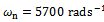 and damping factor
 The stability characterisation is in the form of stability chart in which parameter space of spindle speed and depth of cut is demarcated into stable and unstable domains by stability transition curve. In literature such charts are normally validated by comparing the results of two different methods[3, 4] but in this work accurate MATLAB dde23 solution of parameter points are used in validation. This is a unique feature of this work.Parameter points are picked from the stability transition curve and substituted into the monodromy operator for extraction of critical characteristic multipliers. The result that either a pair of complex conjugate critical characteristic multipliers or a critical characteristic multiplier -1 confirms the prior result that either secondary Hopf bifurcation or flip bifurcation occur in milling[10]. The low spindle speed range in which
  rpm is seen to exhibit only secondary Hopf bifurcation while the high spindle speed range in which
  rpm is seen to exhibit both types of bifurcation. As a major contribution of this paper, the lobes of the transition curve in which secondary Hopf bifurcation occurs are analyzed. It is discovered that critical characteristic multipliers are almost pure imaginary at the minimum points of the lobes and almost pure real at the extremities of the lobes. Migration from the minimum points to the extreme points causes the critical characteristic multipliers to gradually change from
  to -1. This means that bifurcation gets towards flip away from defined minimum points. It is then concluded in this work that though flip bifurcation is not seen in the low spindle speed domain, it is expected to occur in the immediate vicinity of intersection of two secondary Hopf bifurcation lobes. The aforementioned discoveries lead to the postulation of an equation describing the infinitely many but discrete secondary Hopf bifurcation chatter frequencies at minimum points of milling stability chart in terms of minimum point spindle speeds.
2. Mathematical Model
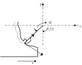
In the dynamical model shown in figure2, the tool is given a spindle speed Ω in revolutions per minute while the workpiece has a prescribed feed velocity v imparted on it via the worktable. The tool and workpiece are engaged at a radial immersion of  . The parameters of the milling process as depicted on the dynamical model are; mmass of tool, c the equivalent viscous damping coefficient modelling the hysteretic damping of the tool system and k the stiffness of the tool system. Figure2 is a single degree of freedom vibration model of an end milling tool. Most encountered resonance in machining involves the fundamental natural frequency thus single degree of freedom vibration is satisfactory when it is well separated from the higher natural frequencies[11].
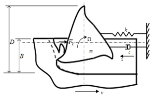 | Figure 2. Dynamical model of end-milling |
The free-body diagram for the tool dynamics is as shown in figure3.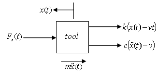 | Figure 3. Free-body diagram of tool dynamics |
The differential equation governing the motion of the tool as seen from the free-body diagram is | (1) |
A tool-workpiece disposition as shown in figure4 is considered for the jth tooth of the tool. In figure4 the cutting force is considered as having normal and tangential components designated  and
and  respectively. Axial component of cutting force is neglected because helix angle is considered zero. The x- component of cutting force for the tool thus becomes
 | (2) |
is the number teeth on the milling tool indexed with the values j=1, 2, 3......N. The instantaneous angular position of a tooth j is . In this work
  is measured clockwise relative to the negative y- axis to give
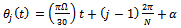 | (3) |
where α is the initial angular position of the tooth indexed 1. Screen or switching function for the jth tooth  could either have the values 1 or 0 depending on whether the tooth is active or not. At radial immersion
 , the screen function is formulated for end milling process of figure2 to have the form
 | (4) |
Since slotting or full-immersion end-milling is considered,  is put into equation (4) to get the screen function as
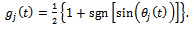 | (5) |
 | Figure 4. Milling tooth-workpiece disposition |
The cutting force on jth tooth has both tangential  and normal
  components as seen in figure 4. The tangential cutting force for the j tooth is given by the non-linear law[10]
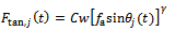 | (6) |
where  is depth of cut,
  is the cutting coefficient associated with the workpiece,
  is the actual feed and γ is an exponent that is usually less than one having a value of
  for the three-quarter rule. The empirical relationship connecting the milling tangential and normal cutting forces in the works of Balint, Bali and Tlusty is seen in[10] to be governed by the equation
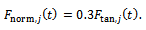 | (7) |
The actual feed rate  is the difference between present and one period delayed position of tool, thus
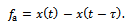 | (8) |
Equations (6), (7) and (8) taken together give  | (9) |
where 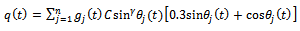 is a
is a  periodic function. Introducing Equation (9) into the equation of motion of the tool system (1) gives
 | (10) |
Suppose the motion of the tool is assumed to be a linear superposition of prescribed feed motion vt, tool τ-periodic response  due to periodic force stemming from regular engagement and dis-engagement between the tool and workpiece and perturbation
  [10] mainly due to regenerative effects then
 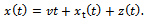 | (11) |
Substitution of equation (11) into equation (10) gives | (12) |
Without perturbation (that is , equation (12) simplifies to
 | (13) |
Equation (13) governs the periodic motion of the system driven by a periodic force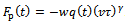 . Equation (13) means that equation (12) becomes
  | (14) |
Put in Taylor series about  and linearizing, equation (14) becomes
 | (15) |
where 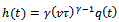 is the time-varying specific force variation. Equation (15) is re-written with the following compact notations;
  and
and  , to give equation (16) which is a form similar to damped delayed Mathieu equation. Equation (16) governs regenerative vibration of linear milling systems.
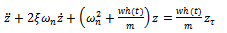 | (16) |
With the substitutions 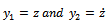 made, equation (16) could be put in state differential equation form as
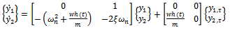 | (17) |
where .The natural frequency and damping ratio of the tool system are given in terms of modal parameters
  respectively as
  and
and . These modal parameters are easily extracted from experimental plot of the tool frequency response function
 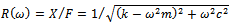 for forced single degree of freedom vibration.
3. Chatter Stability Analysis via Full-discretization Method
A method of full-discretization is first developed by Ding et al for study of milling stability[9]. Equation (17) is denoted as follows;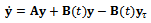 | (18) |
where The full-discretization method as proposed by Ding et al is summarized[12] as follows; the discrete delay τof the system is first divided into k equal time intervals
  where
where . For
. For equation (18) is approximated as
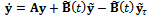 | (19) |
where  and
and 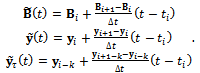 | (20) |
It should be understood that  equals
 . Equation (19) is solved as an ordinary differential equation to give
 | (21) |
where 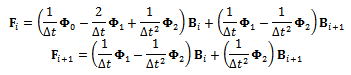 and
and 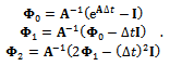 Equation (21) is re-arranged to give
 | (22) |
This is put in matrix form to give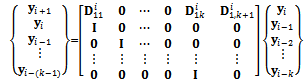 | (23) |
where If equation (23) is designated as
  the discrete map for the system becomes
 | (24) |
Equation (24) is a  -dimensional discrete time map of the system with the Floquet transition matrix
  acting as a linear operator that transforms the delayed state
  to the present state
 . The matrix
  is also called the monodromy or principal matrix of the system. The nature of its eigenvalues also called characteristic multipliers determines the condition of stability of the system. The necessary and sufficient condition for asymptotic stability of the system is that each of the eigenvalues of the monodromy matrix has a magnitude that is less than one. In other words, all the eigen-values of the matrix
  must exist within a unit circle centred at the origin of the complex plane. Since the magnitude of the eigen-values depends on the cutting parameter combination, the parameter space of the system has to be demarcated into stable and unstable sub-domains. This is achieved on the cutting parameter plane of spindle speed and depth of cut by tracking the stability transition curve along which at most two of the characteristic multipliers lie on the unit circle.In order to ascertain nature of milling stability boundary frequencies, a pair of complex conjugate characteristic multipliers
  is considered such that a solution of form
 exists. This is expected of a linear equation, where
  and
and  are τ-periodic. For the case of period one bifurcation μ=1 thus
  and
and  meaning that
  . Putting this result into equation (1) gives that characteristic multiplier leaving the unit circle at +1 results in a damped oscillator
  which by Routh-Hurwitz criterion is asymptotically stable for
 . Period one bifurcation is thus excluded as a form of loss of stability for the linear milling process with positive damping.Period two or period doubling or flip bifurcation occurring means that
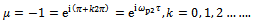
 . Thus;
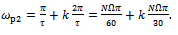 | (25) |
 | Figure 5. Flip bifurcation |
The number of teeth of the milling tool N is 3. Equation (25) gives that there are infinitely many stability boundary frequencies stemming from period two bifurcation. The subscript ‘p2’ is used on the period two bifurcation chatter frequency to differentiate it from other types of stability boundary frequencies. Period two bifurcation for milling process is illustrated in figure 5.Stability boundary frequencies arising from secondary Hopf or Neimark-Sacker bifurcation are extracted from Fourier analysis of the equation 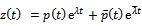 [10]. This type of critical condition results in the equation
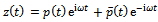 . By Fourier analysis of the periodic function
 , the results obtained are[13];
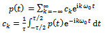 | (26) |
where  is the fundamental natural frequency of the system. Use made of the result of Fourier analysis of
  gives a solution of form
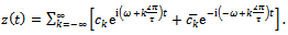 | (27) |
It becomes clear that the infinitely many secondary Hopf bifurcation stability boundary frequencies are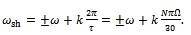 | (28) |
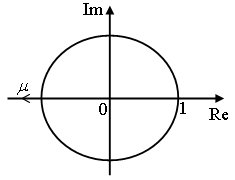
Secondary Hopf bifurcation is shown in figure6. 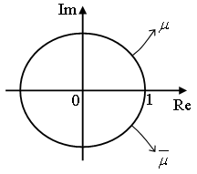 | Figure 6. Secondary Hopf bifurcation |
4. Result, Validation and Discussions
Making use of the Floquet transition matrix 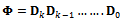 of the discrete map of the system as given in equation (24) in eigen-value analysis, the stability chart generated for the system under study with parameters;
 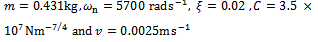 is shown in figure7. In figure 7, the sub-domain of asymptotic stability is grey while that of instability is filled with dark colour. The validity of this chart is partly based on MATLAB dde23 solution[8] of equation (17) at selected points on the parameter space of the machine. Stable MATLAB dde23 solutions are shown marked with star while the unstable (chatter) solutions are marked with diamond on the stability chart. It is thus seen that a very good agreement exists between MATLAB dde23 analysis and the generated chart, a pointer to validity of analysis.
 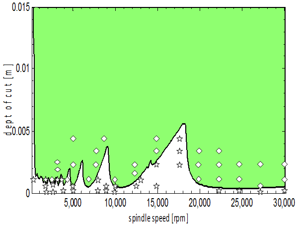 | Figure 7. Stability chart of the studied system, grey and dark subdomains are for stable and chatter operations respectively. Star and diamond are marks for stable and unstable MATLAB dde23 solutions respectively |
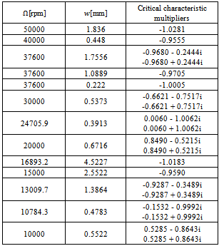
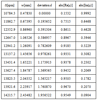
In order that the type of bifurcation occurring at different portions of the stability transition curve be determined, some selected critical parameter combinations are inserted into the monodromy matrix and the critical characteristic multipliers extracted. Table1 is built from MATLAB eigen-value analysis of system’s monodromy matrix at selected critical parameter combinations of high speed stability chart shown in figures 8. Resulting critical characteristic multipliers of selected critical points are given in column3 of table1. The selected critical parameter combinations are marked with either star or circle on the transition curves depending on whether flip or secondary Hopf bifurcation is occurring as judged from table1. A pair of complex conjugate critical characteristic multipliers each of unit modulus or a single critical characteristic multiplier that approximately equals -1 results. Points on the stability transition curve at which change in nature of bifurcation occurs are marked with triangle. The slight deviation of magnitudes of estimated critical characteristic multipliers from correct value of unity is considered to be as a result of error of numerical analysis. The conclusion thus drawn from table1 is that in conformity with theory, the high speed stability chart exhibits either flip or secondary Hopf bifurcation. This result further validates the stability analysis conducted in this work. Another point of note regarding each of the secondary Hopf bifurcation lobes of high spindle speed range is that pair of complex conjugate critical characteristic multipliers get closer to the imaginary axis as critical parameter combination gets towards the minimum point of the lobes. The minimum points are marked with vertical arrows. When critical parameter combination moves away from a minimum point along a secondary Hopf bifurcation lobe, bifurcation occurs closer to the negative real axis as depth of cut increases. For example the minimum point (24705.9, 0.0003913) has critical characteristic multiplier as μ= 0.0060 - 1.0062i while other critical points (30000, 0.0005373), (20000, 0.0006716) and (37600, 0.0017556) in order of increasing depth of cut from the minimum point have critical characteristic multipliers -0.6621 - 0.7517i, 0.8490 - 0.5215i and -0.9680 - 0.2444i. To further quantify this phenomenon, critical points marked with diamond are selected between the minimum point marked A and point B at which secondary Hopf bifurcation gives way for Flip bifurcation as shown in columns 1 and 2 of table2. The vertical deviation (d) of selected points from A are given in column3 of table2 while the moduli of the real and imaginary parts the resulting secondary Hopf bifurcation critical characteristic multipliers are given in columns 4 and 5 respectively.  and
and  which are the absolute values of real and imaginary parts of resulting critical characteristic multipliers μ are plotted against d in marked full and dashed line graphs respectively as shown in figure9. It is seen that R increases towards 1 while I decreases from 1 towards 0 as d increases.In the light of table1, figure9 and the fact that the relationship between a characteristic multiplier
  and a corresponding characteristic exponent
  is
is , at minimum points the relationship becomes
  where
where  such that
 ,
,  The meaning from equation (28) is that the infinitely many but discrete secondary Hopf bifurcation chatter frequencies at minimum points is postulated to be
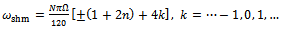 | (29) |
To preclude negative chatter frequencies at minimum points in the use of equation (29), only positive values of k should be considered and the  sign dropped such that equation (29) becomes
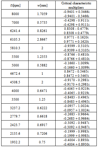
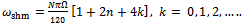 .Any chatter frequency becoming equal to any of the natural frequencies of the tool will cause resonant effect. This could be very damaging since tool materials have very poor damping properties. The result of eigen-value analysis of the monodromy matrix at marked points of low speed stability chart shown in figure10 gives that either flip bifurcation does not occur or that ranges of flip bifurcation are too small to be seen at low speed of full immersion three tooth end-milling. Thus all visible component lobes of low speed chart are of secondary Hopf bifurcation type. It is inferred from table3 that In conformity with what is observed for secondary Hopf bifurcation lobes of the high speed stability chart, all minimum points of low speed stability chart cause location of critical characteristic multipliers to be very close to the imaginary axis while moving away along the curves from these minimum points causes secondary Hopf bifurcation to occur closer to the negative real axis. In other words it could be said that bifurcation gets towards flip away from defined minimum points of stability transition curve of full immersion three tooth end-milling. From this trend it is logical to say that though not seen, flip bifurcation occurs at the intersection of two secondary Hopf bifurcation lobes in the low spindle speed range of full immersion three tooth end-milling . These observations point to the similarity in dynamic stability of turning process and continuously engaged low speed milling process. This similarity is expected to get stronger as the number of teeth of end-miller increases.
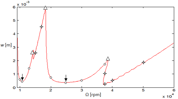 | Figure 8. High speed stability chart of the studied system. Stars mark flip bifurcation (FB) points while circles mark secondary Hopf bifurcation points. Arrows mark minimum points of secondary Hopf curves |
Table 1. Critical cutting parameter combinations of the high speed stability transition curve and resulting critical characteristic multipliers
 |
| |
|
Table 2. Critical cutting parameter combinations of a secondary Hopf bifurcation lobe and the absolute value of the real and imaginary parts of the resulting critical characteristic multipliers
 |
| |
|
Table 3. Critical cutting parameter combinations of the low speed stability transition curve and resulting critical characteristic multipliers
 |
| |
|
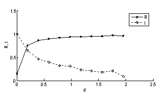 | Figure 9. The absolute value of the real part (R) and the imaginary part (I) of the resulting critical characteristic multipliers of a secondary Hopf bifurcation lobe of the High speed stability chart against deviation (d) from minimum point depth of cut |
 | Figure 10. Low speed stability chart. Circles mark secondary Hopf bifurcation (SHB) points while no Flip bifurcation (FB) points are seen though expected at the intersection between secondary Hopf curves |
5. Conclusions
Stability analysis of a full immersion three tooth end-milling process with the parameters; tool mass  tool natural frequency
  damping factor
  and workpiece cutting coefficient
  using the method of full-discretization results in a transition curve that demarcates the parameter plane of spindle speed and depth of cut into stable and unstable sub-domains. The validity of this chart is partly based on its agreement with MATLAB dde23 analysis of governing periodic second-order delay differential equation at selected points of the parameter space.The stability transition curve is shown via MATLAB eigen-value analysis of the finite-monodromy matrix of the system to be composed of lobes at which either secondary Hopf bifurcation or flip bifurcation is occurring. This is deemed to contribute to validity of analysis since it is in agreement with theory and experiment.The two types of bifurcation are discovered to be visible for high speed range while only secondary Hopf bifurcation is visible for the low spindle speed range of the studied system. It is also discovered that for the studied full immersion three tooth end-milling process that critical characteristic multipliers are almost pure imaginary at the minimum points of secondary Hopf bifurcation lobes and get closer to the negative real axis when critical points get further away from minimum points. In other words bifurcation gets towards flip away from defined minimum points. Flip bifurcation in the low spindle speed domain is concluded to occur in the immediate vicinity of intersection of two secondary Hopf bifurcation lobes. Equation describing the infinitely many but discrete secondary Hopf bifurcation chatter frequencies at minimum points of milling stability chart is postulated. This equation is given in terms of minimum point spindle speeds.
References
| [1] | G. Stépán, R. Szalai, T. Insperger , Nonlinear Dynamics of High-Speed Milling Subjected to Regenerative Effect, to appear in the book Nonlinear Dynamics of Production Systems, edited by Gunther Radons, Wiley-VCH, New York, 2003, 1-2. |
| [2] | M.A. Davies, T. J. Burns, T. L. Schmitz, High-Speed Machining Processes: Dynamics of Multiple Scales, National Institute of Standards and Technology, 100 Bureau Drive, Gaithersburg MD 20899, USA, (1999). |
| [3] | T. Insperger, B.P. Mann, G. Stepan, P.V. Bayly, Stability of up-milling and down-milling, part 1: alternative analytical methods, International Journal of Machine Tools and Manufacture 43 (2003) 25–34. |
| [4] | O. A. Bobrenkov , F. A. Khasawneh , E. A. Butcher , B. P. Mann, Analysis of milling dynamics for simultaneously engaged cutting teeth, Journal of Sound and Vibration 329 (2010) 585–606. |
| [5] | E. A. Butcher, H. Ma, E. Bueler, V. Averina , Z. Szabo, Stability of linear time-periodic delay-differential equations via Chebyshev polynomials, International Journal for Numerical Methods in Engineering, 59 (2004) 895–922. |
| [6] | T. Insperger, G. Stepan, Semi-discretization method for delayed systems, International Journal For Numerical Methods In Engineering, 55(2002) 503–518. |
| [7] | T. Insperger, G. Stepan, Stability of Milling Process, Periodica Polytechnica 44 (1) (2000) 47–57. |
| [8] | C. G. Ozoegwu, Chatter of Plastic Milling CNC Machine: Master of Engineering thesis, Nnamdi Azikiwe University Awka (2011). |
| [9] | Y. Ding, L.M. Zhu, X.J. Zhang, H. Ding, A full-discretization method for prediction of milling stability, International Journal of Machine Tools and Manufacture 50 (2010) 502–509. |
| [10] | T. Insperger, Stability Analysis of Periodic Delay-Differential Equations Modelling Machine Tool Chatter: PhD dissertation, Budapest University of Technology and Economics (2002). |
| [11] | G. Stepan, Delay-differential Equation Models for Machine Tool Chatter: in Nonlinear Dynamics of Material Processing and Manufacturing edited by F. C. Moon, John Wiley & Sons, New York, 1998 pp. 165-192. |
| [12] | T. Insperger, Full-discretization and semi-discretization for milling stability prediction: Some comments, International Journal of Machine Tools and Manufacture 50 (2010) 658–662. |
| [13] | S. S. Rao, Mechanical Vibrations, 4th ed., Dorling Kindersley, India, 2004, p.290. |
 Abstract
 Reference
 Full-Text PDF
 Full-Text HTML