-
Paper Information
- Next Paper
- Previous Paper
- Paper Submission
-
Journal Information
- About This Journal
- Editorial Board
- Current Issue
- Archive
- Author Guidelines
- Contact Us
International Journal of Mechanics and Applications
p-ISSN: 2165-9281 e-ISSN: 2165-9303
2012; 2(6): 113-116
doi: 10.5923/j.mechanics.20120206.02
Study of Effect of Interface Pressure on the Stress Analysis of Ceramic Lined Pressure Vessels
 Abstract
 Reference
 Full-Text PDF
 Full-Text HTML
K. V. S. Seshendra Kumar
Dept. of Industrial Production Engineering, GITAM Institute of Technology, Gitam University, Visakhapatnam, India
Correspondence to: K. V. S. Seshendra Kumar , Dept. of Industrial Production Engineering, GITAM Institute of Technology, Gitam University, Visakhapatnam, India.
| Email: |  |
Copyright © 2012 Scientific & Academic Publishing. All Rights Reserved.
The present work deals with the effect of interface pressure on the stress and fracture analysis of carbon-epoxy dual jacketed pressure vessels at elevated temperatures. Pre-stress and firing stress is determined for an initial residual interface pressure applied between liner and jacket. The effect of a uniform 100℃ temperature rises above ambient had mixed results for a carbon-epoxy jacketed vessel, due to the differential thermal expansion. While jacket stresses increased moderately and further exceeded typical material strengths, liner stresses decreased significantly and improved structural integrity. The effect of a temperature rise for a steel jacketed vessel was deleterious. Jacket stresses decreased, but with no effect on structural integrity, while liner stresses increased, to the detriment of integrity.
Keywords: Dual Jacketed Vessels, Fracture Analysis, Interface Temperature, Firing Stress, Pre-Stress
Cite this paper: K. V. S. Seshendra Kumar , "Study of Effect of Interface Pressure on the Stress Analysis of Ceramic Lined Pressure Vessels", International Journal of Mechanics and Applications, Vol. 2 No. 6, 2012, pp. 113-116. doi: 10.5923/j.mechanics.20120206.02.
Article Outline
1. Introduction
- Ceramic-lined cannons have gained attention in recent years[1] due to increased and more sustained combustion gas temperatures used to attain improved cannon performance. Thermal damage of the electroplated chromium used on a cannon bore has become a significant erosion failure mode for today’s gun barrels[2]. The higher elevated-temperature strength of ceramics provides significantly improved resistance to thermal damage in the severe thermo- mechanical environment of cannon firing[3].Methods of analysis will be generally similar to those described recently by Parker et al.[4], where various combinations of autofrettage and external tension wrapping of steel-lined, carbon-fiber jacketed tubes were studied. Here, the liner-jacket analysis will be for two types of ceramic liner, Si3N4 and SiC, and two types of jacket, A723 pressure vessel steel and carbon-epoxy laminate. Emphasis is on composite jacket inner radius stresses that can exceed typical failure strengths and on ceramic liner inner radius stresses that can result in alarmingly small critical crack sizes for brittle fracture. The analysis is for a representative initial residual interface pressure between liner and jacket that would be expected for either shrink fitting or tension wrapping of a liner-jacket vessel. The work of Malinowski and Magnuki[5] employed parametric discrete optimization techniques to design internal reinforcements of pressure vessels by minimizingthe reinforcement mass considering stress constraints. Following an analytical approach, Banichuk et al.[6] used variational calculus to find the head meridian profile optimal curve in order to maximize the ratio between head volume and mass subjected to stress constraints.A follow up of this work was provided by Du and Olhoff [7] and Zheng et al.[8], who extended the investigation to three-dimensional structures. However, they considered as objective function the minimization of mean compliance without stress constraints, which is not realistic for pressure vessel design. In fact, the solution of topology optimization considering stress constraints is still an open problem[9-11].Recently, Blachut and Magnuki[12] published an extensive review about modeling and optimization of pressure vessels where they mention that, in the optimization field, there are still few pieces of work related to pressure vessel design. This work provides a contribution along those lines by presenting an integrated approach in which the entire vessel is considered in the optimization process.
2. Stress Analysis
2.1. Fracture Analysis
- Fracture analysis is done to calculate the fracture thickness values at the inner radius of the ceramic lined vessel can be calculated using the formula given below.Crack Thickness,

2.2. Effect of Jacket
- Stresses were calculated for a Silicon-nitride lined vessel with dual jacket is listed in Table 1. Figure 1 shows the results for the C-epoxy jacket, including prestress, firing and total stresses versus radial position, r/a. The prestress is due to the interface pressure at the junction, already discussed. The pressure applied to the vessel inner radius was 500 MPa, based on the 400–700 MPa pressures used in modern cannons. Note that, although the radial prestress does not exceed the C-epoxy compressive strength, when the firing stresses are added, both radial and hoop stresses exceed the respective strength values for C-epoxy. The total radial stress at the interface is 2300 MPa, compared with 120 MPa compressive strength, and the total jacket hoop stress is 770 MPa, compared with the 600 MPa tensile strength. The problems under consideration are a composite pressure vessel shell which has a liner and a single jacket or a dual jacket. Stress analysis is to be done for the single jacket vessel and dual jacket vessel and the stress variations are to be studied. The wear and erosion is also high in gun barrels. So suitable materials are to be chosen for this application. The different materials taken for this purpose are ceramic materials like Si3N4 and SiC for liner, and C-epoxy and A723 Steel for Jacket.
2.3. Effect of Temperature
- The effect of moderately elevated temperature on total stresses in a ceramic lined vessel is of interest for cannons and some other applications. Figures 4 and 5 show results for C-epoxy or steel jacked, Si3N4 lined vessels, respectively, at 25°C ambient temperature and after a uniform rise to 125°C. First, note that the ambient results ~25°C; solid lines! are nearly identical for the two vessel ~Fig. 4! the jacket stresses at 125°C are slightly increased, adding to the problem of exceeding the material strength, discussed earlier. However, the liner integrity is improved with the increase in temperature. The stresses are decreased due to the favorable differential expansion between C-epoxy jacket and ceramic liner. This differential expansion was modeled by an increased 0.13 mm interference between jacket and liner at 125°C, compared with 0.10 mm at 25°C.The effect of temperature on total stresses with a steel liner in Fig. 5 shows that jacket stresses are slightly reduced, but to no advantage in structural integrity because of the adequate strength of steel. However the liner integrity suffers at high temperature, because differential expansion decreases the interference.
3. Results and discussion
3.1. Stress Variation for Dual Jacketed Vessel
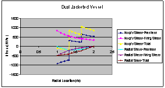 | Figure 1. Variation of firing & pre-stress for continuous liner and jacket vessels |
3.2.Temperature Effect
- (a) SiC-C epoxy Vessel:
| |||||||||||||||||||||||||||||||||||||||||
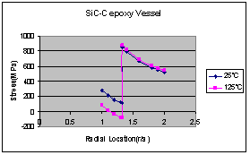 | Figure 2. Variation of temperature stress for SiC-C epoxy vessel |
| |||||||||||||||||||||||||||||||||||||||||
 | Figure 3. Variation of temperature stress for SiC-steel epoxy vessel |
3.3. Fracture Analysis
- The fracture analysis is performed for the two ceramic materials for single and dual jacketed vessels and tabulated in Table4. It is observed that silicon carbide materials are prone to less crack thickness than silicon nitride materials.
| ||||||||||||||
4. Summary & Conclusions
- The type of jacket had no significant effect on liner or jacket stresses, because the elastic modulus of the carbon-epoxy considered was close to that of steel. However, the total prestress, firing radial and hoop stresses at the inner radius of the carbon epoxy jack et exceeded typical material strengths in these directions. The result of the fracture analysis is that a ceramic lined pressure vessel with a thin, low modulus, high toughness ceramic liner and a dual-steel interference-fitted jacket would have the best structural integrity of the cases considered. However, it is emphasized that the very small critical crack size for brittle fracture that is inherent in the use of ceramics demands the utmost care in pressure vessel design.
References
| [1] | Katz, R. N., 1996, Ceramic Gun Barrel Liners: Retrospect and Prospect," Proceedings of Sagamore Workshop on Gun Barrel Wear and Erosion, Army Research Laboratory Report, 66-84. |
| [2] | Underwood, J. H., Parker, A. P., Vigilante, G. N., and Cote, P. J. 2003, Thermal Damage, Cracking and Rapid Erosion of Cannon Bore Coatings, ASME J. Pressure Vessel Technol., 125(1), 299-304. |
| [3] | Underwood, J.H., Todaro, M. E., and Vigilante, G. N,.2004, Modeling of Transient Thermal Damage in Ceramics for Cannon Bore Applications, Ceramic Engineering and Science Proceedings, 25(1), 12-16. |
| [4] | Parker, A. P., Troiano, E., and Underwood, J. H 2004, Stresses Within Compound Tubes Comprising a Steel Liner and an External Carbon-Fiber Wrapped Laminate, ASME Pressure Vessels and Piping Conference, ASME, New York. |
| [5] | Malinowski M, Magnucki K.,2005, Optimal design of sandwich ribbed flat baffle plates of a circular cylindrical tank. International Journal of Pressure Vessels and Piping 82(3),227-233. |
| [6] | Banichuk NV, Ragnedda F, Serra M., 2008, Optimization of mass effectiveness of axisymmetric pressure vessels. Structural and Multidisciplinary Optimization,35(5),453-459. |
| [7] | Du J, Olhoff N.,2004, Topological optimization of continuum structures with design dependent surface loading - part II: algorithm and examples for 3D problems.Structural and Multidisciplinary optimization 2004;27(3):166-177. |
| [8] | Zheng B, Chang CJ, Gea HC.,2009, Topology optimization with design-dependent pressure loading. Structural and Multidisciplinary Optimization,38(6),535-543. |
| [9] | Duysinx P, Bendsoe MP.,1998, Topology optimization of continuum structures with local stress constraints. International Journal for Numerical Methods in Engineering,43(8),1453-1478. |
| [10] | Stump FV, Silva ECN, Paulino GH.,2007, Optimization of material distribution in functionally graded structures with stress constraints. Communications in Numerical Methods in Engineering,23(6),535-551. |
| [11] | Amstutz S, Novotny AA.,2010, Topological optimization of structures subject to Von Mises stress constraints. Structural and Multidisciplinary Optimization, 41(3),407-420. |
| [12] | Blachut J, Magnucki K.,2008,Strength, stability, and optimization of pressure vessels:review of selected problems. Applied Mechanics Reviews,61(6), 608-610. |
| [13] | MATLAB. R2010a documentation. The MathWorks, Inc.; 2010. |
| [14] | Fenner, R. T. 1989, Mechanics of Solids, Blackwell Scientific Publications, Oxford, UK, 566-569. |
| [15] | D'Andrea, G., Cullinam, R. L., and Croteau, P. J. 1978, "Refractory-Lined Composite Pressure Vessels," US Army Benet Technical Report ARLCB- TR-78023, Watervliet, New York. |
| [16] | Rawal, S. P., and Goodman, J. W. 2001, "Space Applications," in ASM Handbook, 21, Composites, ASME International, Material Park,21(1), 1033-1042. |
| [17] | Walter H. Tarn, lan A. Ballinger, Jerry Kuo, and William D. Lay, 2001, "Stiffened and Prestressed Composite Overwrapped Pressure Vessels", SAMPE Symposium. |
| [18] | John H. Underwood, Anthony P. Parker, 2004. Stress and Fracture Analysis of Ceramic Lined, Composite or Steel Jacketed Pressure Vessels, ASME Journal of Pressure Vessel Technology, 126(1), 485-485. |
| [19] | J.H. Underwood, M.E. Todaro, M.D. Witherell, A.R Parker, 2008, "Analysis of firing and fabrication stresses and failure in ceramic lined Cannon Tubes", Developments in Advanced Ceramics and Composites: Ceramic Engineering and Science Proceedings, 26(8), 2-10. |