Saeed Asiri
King Abdulaziz University, 21589, Jeddah, P. O. Box. 80204, Saudi Arabia
Correspondence to: Saeed Asiri , King Abdulaziz University, 21589, Jeddah, P. O. Box. 80204, Saudi Arabia.
| Email: |  |
Copyright © 2012 Scientific & Academic Publishing. All Rights Reserved.
Abstract
This research is to design and implement a new kind of agitators called differential agitator. The Differential Agitator is an electro- mechanic set consists of two shafts. The first shaft is the bearing axis while the second shaft is the axis of the quartet upper bearing impellers group and the triple lower group which are called as agitating group. The agitating group is located inside a cylindrical container equipped especially to contain square directors for the liquid entrance and square directors called fixing group for the liquid exit. The fixing group is installed containing the agitating group inside any tank whether from upper or lower position. The agitating process occurs through the agitating group bearing causing a lower pressure over the upper group leading to withdrawing the liquid from the square directors of the liquid entering and consequently the liquid moves to the denser place under the quartet upper group. Then, the liquid moves to the so high pressure area under the agitating group causing the liquid to exit from the square directors in the bottom of the container. For improving efficiency, parametric study and shape optimization has been carried out. A numerical analysis, manufacturing and laboratory experiments were conducted to design and implement the differential agitator. Knowing the material prosperities and the loading conditions, the FEM using ANSYS11 was used to get the optimum design of the geometrical parameters of the differential agitator elements while the experimental test was performed to validate the advantages of the differential agitators to give a high agitation performance of lime in the water as an example. In addition, the experimental work has been done to express the internal container shape in the agitation efficiency. The study ended up with conclusions to maximize agitator performance and optimize the geometrical parameters to be used for manufacturing the differential agitator.
Keywords:
Differential Agitators, Parametric Optimization, Shape Optimization, Agitation, FEM, ANSYS11
Cite this paper:
Saeed Asiri , "Design and Implementation of Differential Agitators to Maximize Agitating Performance", International Journal of Mechanics and Applications, Vol. 2 No. 6, 2012, pp. 98-112. doi: 10.5923/j.mechanics.20120206.01.
1. Introduction
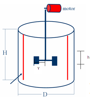
Agitation is the process of induce motion of material in a specified way. In the chemical and other processing industries, many operations are dependent to a great extent on effective agitation and mixing of fluids. Generally, agitation refers to forcing a fluid by agitator means to flow in a circulatory or other pattern inside a vessel (see Figure 1.1). In spite that agitator is very effective in industry today but still has many problems which affect the agitation process. Most agitator cause vortex in the center of the liquid which enforces the manufacturers to put Baffles inside the agitating tanks. In addition, the classical agitator generate bubbles inside the gas causing dribble which is prohibited in liquids of low flash points. These agitators cause bubbles in the liquid of the liquid vapor called Cavitations. Cavitations lead to lowering the agitating efficiency due to storing a great amount of energy in the form of pressure. Agitation has various purposes such suspending solid particles, blending miscible liquids, dispersing a gas through a liquid in the form of small bubbles, dispersing a second liquid immiscible with the first, to form an emulsion or suspension of fine drops, and promoting heat transfer between the liquid and a coil or jacket. There are some factors affecting the efficiency of agitating; some are related to the liquid characteristics such as viscosity and density, and some are related to the geometry such as the container diameter (D), impeller length (Y), rotating speed (N), height of impellers from bottom of the container (h) as shown in Figure 1.2, the later affects the gathered materials in the bottom of the container because this amount can't be minimized to a great value as it demands a high capacity of the motor due to surface tension of the liquid[1].Other characteristics of mixing include the necessity of performing the process to make the liquid experience all kinds of movement inside the container (from downwards to upwards a vice versa – cyclic – diagonal), Figure 1.3 and Figure 1.4 show the different types of motion of agitator .When agitating two liquids that have a thicker one or agitating a solid material in order to solute in the liquid, various techniques are used; bearing shaft in which different designs are fixed of agitator impellers such as :1. Axial Impellers 2. Centrifugal Impellers3. Multi Stage Impellers4. Inclined Impellers 5. Helical/Screw Impellers 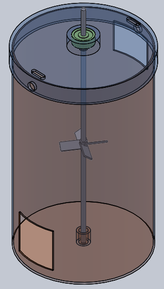 | Figure 1.1. Normal Agitator |
 | Figure 1.2. An example of a classical agitator |
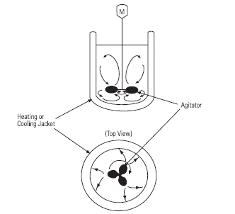 | Figure 1.3. Agitators cycle motion[2] |
The first four kinds depend on mixing through withdrawing the denser liquid upwards but they have some defects or problems as follow[1]:1. Most agitator cause vortex in the center of the liquid the matter that enforces the manufacturers to put Baffles inside the agitating tanks.2. Most agitator lead to bubbles inside the gas causing dribble which is prohibited in liquids of low flash points.3. These agitators cause bubbles in the liquid of the liquid vapor which causes cavitations. These cavitations leads to lowering the agitating efficiency due to storing a great amount of energy in the form of pressure.4. To design the agitators, there is a need to calculate the electric power of the motor according to the tank size and liquid type.5. When calculating the electric power of a motor, we are urged suppose that the tank is cylindrical.6. There is no a universal system till now that is valid for all liquids and all tanks except the differential agitator.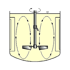 | Figure 1.4. Agitators up down motion[2] |
2. Background
Weber[3] , develops a new type of agitator for continuous flow reactor for high viscosity materials. A reactor of one or more stages for the continuous processing of high viscosity material wherein each stage is provided with a stage barrier for directing and controlling. The flow of process material within each stage of the reactor and for controlling the egress of material from each stage of the reactor. A rotor shaft is rotatable mounted at opposite end walls of the reactor and extends through the reactor coaxially with its longitudinal axis. Fix ably attached to the rotor shaft for rotation within each stage is a mixing assembly including a cylindrical draft tube positioned coaxially with respect to the reactor side wall. A helical screw mounted within the draft tube with a ribbon agitator mounted within the annular space between the draft tube. The reactor wall which having a pitch opposite to the helical screw. The agitator and the helical screw have pre selected relative pitches and dimensions so that when rotated they cooperate with the stage barrier. The vessels wall and the draft tube to re-circulate a predetermined portion of process material in a fixed flow pattern within each stage while advancing a remaining predetermined portion of the process material out of the stage in one direction. Weetman and Howk[4] ; developed a new type of mixer to provides axial flow in a non uniformal flow field. Such as may be established by gas and provides a large axial flow volume without flooding and withstands variable loads on the blades. Thereby providing for a reliable operation. The mixer impeller is made up of paddle shaped blades, which near their tips (e.g., at 90% of the radius of the impeller from its axis of rotation) and which are of a width at least 40% of the impeller's diameter. The blades also have camber and twist. They are formed by establishing bending moments which form the blades into sections which are curved and flat, with the flat section being at least in the central area of the base of the blades. The hub for attaching the blades to the shaft of the mixer has radically extending arms with flat surfaces. The bases of the blades are spaced from the shaft to define areas there between. These areas are reduced in size, thereby limiting the passage of sparging gas between the blades and the shaft. The strength of the coupling between the blades and the shaft are enhanced by backing plates of the width greater than the width of arms. These backing plates are fastened between arms and the flat sections of blades. Bolts extending through aligned holes in the arms, backing plates and blades provides stronger and secure attachment of impeller blades to the shaft. The impeller will operate reliably in the environment which provides variable loads on the blades. In 1999, Inoue and Saito[5] , improve mixing device and method. The mixing material around inner agitating means in a mixing vessel is urged upward and outward by rotating the inner agitating in one direction. In simultaneously the mixing material around outer agitating is urged downward and inward by rotating the outer agitating in the opposite direction. Consequently the cause of mixing materials urged upward and downward to be circulated by convection in the mixing vessels. The mixing materials urged outward and inward to collide between the inner and outer agitating to forming a high pressure region between the inner and outer agitating. The mixing materials are mashed in high pressure region and well mixed in short time with high efficiency without being agglutinated to the inner agitating. Hockmeyer and Herman[6], Apparatus for processing high viscosity dispersions. The Apparatus for dispersing solid constituent into a liquid immersion mill operating in combination with a low shear mixer blade assembly. Where it sweeps the walls of the tank containing a batch of solid constituents in a liquid circulate the batch through the immersion mill to carry out a milling operation. To establish a relatively high viscosity mixture having a high degree of uniformity. The immersion mill includes an improvement wherein a helical screw impeller is placed within a tubular inlet passage for moving the batch longitudinally through the tubular inlet passage into the immersion mill. The helical screw impeller including a helical flight extending along the length of the tubular inlet passage and having a diameter complementary to the diameter of the tubular inlet passage. The pitch will be less than the length of the tubular inlet passage such that the helical flight spans the diameter of the tubular inlet passage along plural turns of the helical flight . Agitators can be classified based on how a fluid flows through the impeller. The flow of the fluid through the impeller is determined by the design of the agitator casing and the impeller. The three types of flow through the agitator are radial flow, axial flow, and mixed flow. In a radial flow agitator, the liquid enters at the center of the impeller and is directed out along the impeller blades at right angles to the agitator shaft . In an axial flow agitator, the impeller pushes the liquid in a direction parallel to the agitator shaft. Axial flow agitator are sometimes called propeller agitators because they operate essentially the same as the propeller of a boat[7]. Mixed flow agitators borrow characteristics from both radial flow and axial flow agitators. As liquid flows through the impeller of a mixed flow agitator, the impeller blades push the liquid out away from the agitator shaft and to the agitator suction at an angle greater than 90o[8]. A centrifugal agitator with a single impeller that can develop a differential pressure of more than 150 psi between the suction and the discharge is difficult and costly to design and construct. A more economical approach to developing high pressures with a single centrifugal agitator is to include multiple impellers on a common shaft within the same agitator casing[9]. Internal channels in the agitator casing route the discharge of one impeller to the suction of another impeller. The water enters the agitator from the top left and passes through each of the stage impellers in series, going from left to right. The water flows from the volute surrounding the discharge of one impeller to the suction of the next impeller. An agitator stage is defined as that portion of a centrifugal agitator consisting of one impeller and its associated components. Most centrifugal agitators are single-stage agitators, containing only one impeller. An agitator containing seven impellers within a single casing would be referred to as a seven-stage agitator or, generally, as a multi-stage agitator[9]. Agitators Impellers can be open, semi-open, or enclosed. The open impeller consists only of blades attached to a hub. The semi-open impeller is constructed with a circular plate (the web) attached to one side of the blades. The enclosed impeller has circular plates attached to both sides of the blades. Enclosed impellers are also referred to as shrouded impellers. Impellers of agitators are either Single-Suction or Double-Suction Impellers based on the number of points that the liquid can enter the impeller and also on the amount of webbing between the impeller blades. Impellers can be either single-suction or double-suction. A single-suction impeller allows liquid to enter the center of the blades from only one direction. A double-suction impeller allows liquid to enter the center of the impeller blades from both sides simultaneously[9]. The impeller sometimes contains balancing holes that connect the space around the hub to the suction side of the impeller. The balancing holes have a total cross-sectional area that is considerably greater than the cross-sectional area of the annular space between the wearing ring and the hub. The result is suction pressure on both sides of the impeller hub, which maintains a hydraulic balance. There are some parts that affect the efficiency of the agitator and some internal parts are effective in the agitators efficiency and agitation process, like diffuser wearing rings and they also maintain the operation conditions of an agitator to avoid some defects like cavitation[10]. Some centrifugal agitators contain diffusers. A diffuser is a set of stationary vanes that surround the impeller. The purpose of the diffuser is to increase the efficiency of the centrifugal agitator by allowing a more gradual expansion and less turbulent area for the liquid to reduce in velocity. The diffuser vanes are designed in such a way that the liquid exiting the impeller will encounter an ever- increasing flow area as it passes through the diffuser. This increase in flow area causes a reduction in flow velocity, converting kinetic energy into flow pressure. Centrifugal agitators can also be constructed in a manner that results in two distinct volutes, each receiving the liquid that is discharged from a 180o region of the impeller at any given time. Agitators of this type are called double volute agitators (they may also be referred to split volute agitators). In some applications the double volute minimizes radial forces imparted to the shaft and bearings due to imbalances in the pressure around the impeller[11]. Centrifugal agitators contain rotating impellers within stationary agitator casings. To allow the impeller to rotate freely within the agitator casing, a small clearance is designed to be maintained between the impeller and the agitator casing. To maximize the efficiency of a centrifugal agitator, it is necessary to minimize the amount of liquid leaking through this clearance from the high pressure or discharge side of the agitator back to the low pressure or suction side. Some wear or erosion will occur at the point where the impeller and the agitator casing nearly come into contact This wear is due to the erosion caused by liquid leaking through this tight clearance and other causes. As wear occurs, the clearances become larger and the rate of leakage increases. Eventually, the leakage could become unacceptably large and maintenance would be required on the agitators. To minimize the cost of agitator maintenance, many centrifugal agitators are designed with wearing rings[12]. Wearing rings are replaceable rings that are attached to the impeller and/or the agitator casing to allow a small running clearance between the impeller and the agitator casing without causing wear of the actual impeller or agitator casing material. These wearing rings are designed to be replaced periodically during the life of an agitator and prevent the more costly replacement of the impeller or the casing. The flow area at the eye of the agitator impeller is usually smaller than either the flow area of the pump suction piping or the flow area through the impeller vanes. When the liquid being pumped enters the eye of a centrifugal agitator, the decrease in the flow area results in an increase in flow velocity accompanied by a decrease in pressure. The greater the agitator flow rate, the greater the pressure drop between the agitator suction and the eye of the impeller. If the pressure drop is large enough, or if the temperature is high enough, the pressure drop may be sufficient to cause the liquid to flash to vapor when the local pressure falls below the saturation pressure for the fluid being pumped. Any vapor bubbles formed by the pressure drop at the eye of the impeller are swept along the impeller vanes by the flow of the fluid. When the bubbles enter a region where local pressure is greater than saturation pressure farther out the impeller vane, the vapor bubbles abruptly collapse. This process of the formation and subsequent collapse of vapor bubbles in an agitator is called cavitation. Cavitation in a centrifugal agitator has a significant effect on agitator performance. It degrades the performance of an agitator, resulting in a fluctuating flow rate and discharge pressure. It can also be destructive to agitators internal components. When an agitator cavitates, vapor bubbles form in the low pressure region directly behind the rotating impeller vanes. These vapor bubbles then move toward the oncoming impeller vane, where they collapse and cause a physical shock to the leading edge of the impeller vane. This physical shock creates small pits on the leading edge of the impeller vane. Each individual pit is microscopic in size, but the cumulative effect of millions of these pits formed over a period of hours or days can literally destroy an agitator impeller. Cavitation can also cause excessive agitator vibration, which could damage agitator bearings, wearing rings, and seals. A small number of centrifugal agitators are designed to operate under conditions where cavitation is unavoidable. These agitators must be specially designed and maintained to withstand the small amount of cavitation that occurs during their operation. Most centrifugal agitators are not designed to withstand sustained cavitation. Noise is one of the indications that a centrifugal agitator is cavitating. A cavitating agitator can sound like a can of marbles being shaken. Other indications that can be observed from a remote operating station are fluctuating discharge pressure, flow rate, and agitator motor current[12]. Agitators also have many types and designations. The other classification depends on the impeller type, and the following are some different types of impeller[13]. The three bladed marine type propeller is good for homogenizing and it was the first axial flow impeller used in vessels for agitation. It is often supplied with fixed and variable speed portable agitators up to 5HP with impeller diameters up to 150 mm. Marine propellers are too heavy and too expensive compared with hydrofoil impellers. They are usually applied up to 1750 rpm in vessels up to 2000 liters. Viscosity limit is about 5000 cP, Lower Reynold’s Number limit is 200[14]. The marine propellers are used in applications requiring moderate pumping action. These propellers are axial flow impellers. The propeller blades are designed so that the liquid is quickly carried away from the blade without occurrence of cavitations. As such, marine propellers are used for products with lower to medium viscosities. The impeller is the hydrofoil high efficiency impeller, but all vendors have competitive impeller such as heat transfer, blending, and solids suspension at all speeds in all vessels. The economical optimum D/T (0,4 > D/T optimum > 0.6) is greater for hydrofoils than for higher shear impellers lower NRe limit 200[14]. The 6 blade disk (historically known as the Rushton turbine) impeller is very old. Nevertheless, it still has no peer. For some application, it invests the highest proportion of its power as shear of all the turbine impellers, except those (e.g. the cowls impeller) specially designed to create stable emulsions. It is still the preferred impeller for gas liquid dispersion for small vessels at low gas rates, and it is still used extensively for liquid-liquid dispersions, and it is the only logical choice for use with fast competitive chemical reactions, lower NRe limit5[15]. The blade (45 ºC) pitched blade impeller is the preferred choice where axial flow is desired and where there is a need for proper balance between flow and share. It is the preferred impeller for liquid-liquid dispersions and for gas dispersion from the vessel headspace (located about D/3 to D/2 below the free liquid surface) in conjunction with a low 6 Bladed Impeller or a concave blade disk impeller, low NRe limit ≈ 20 The pitched blade Turbine produces less axial flow than hydrofoils but higher shear forces than hydrofoils. It is best suited when both flow velocity and fluid shear are required. The 4-blade flat blade impeller is universally used to provide agitation as a vessel is emptied. It is installed, normally fitted with stabilizers as low in the vessel as is practical. Four Bladed Impeller is often installed at about C/T to provide effective agitation at high batch levels . Lower NRelimit 5 Flat Blade Turbine is a radial flow impeller that is used for low volume stirring[15]. The saw tooth (or cowls type) impeller is the ultimate at investing its power as shear rather than flow. It is used extensively for producing stable liquid-liquid (emulsions) and dense gas-liquid (foams) dispersions. It is often used in conjunction with a larger diameter axial-flow impeller higher on the shaft Lower NRe limit 10 Derya Krom suggests, that it is difficult to disperse chemicals or for mixing powder into the product to form a smooth mixture. The flow pattern of the saw tooth impellers produces very high shear[15]. The 6 blade disk style concave blade impellers which uses half pipes as blades are used extensively and economically for gas dispersion in large vessels (in fermenters up to 350 tons.) at high gas flow rates . This type will handle up to %200 more gas without flooding than will the 6 Blade, and the gassed power draw at flooding drops only about 30%, where as with a 6 BD, the drop in power draw exceeds 50 %. The Gas Turbine is an impeller that provides excellent gas handling. The gas turbine breaks the gas molecules into smaller bubbles, thus increasing the surface area. The gas turbine is designed with special blades that handle higher gas rates for improved process efficiency.
3. Methodology
3.1. Overview
The differential agitator is an electro- mechanic set consists of two shafts. The first shaft is the bearing axis while the second shaft is the axis of the quartet upper bearing impellers group and the triple lower group which are called as agitating group. The agitating group is located inside a cylindrical container equipped especially to contain square directors for the liquid entrance and square directors called fixing group for the liquid exit. 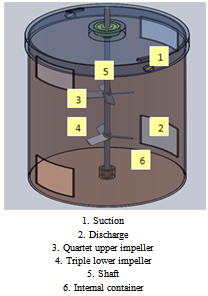 | Figure 3.1. The Differential Agitator (Internal Container) |
The fixing group is installed containing the agitating group inside any tank whether from upper or lower position. The agitating process occurs through the agitating group bearing causing a lower pressure over the upper group leading to withdrawing the liquid from the square directors of the liquid entering and consequently the liquid moves to the denser place under the quartet upper group. Then, the liquid moves to the so high pressure area under the agitating group causing the liquid exit from the square directors in the bottom of the container as shown in Figure 3.1.This agitator is distinguished with the following advantages:1. It does not cause vortex in the center of the liquid so that there is no need to put baffles inside the agitating tanks.2. It does not lead to bubbles inside the gas causing dribble so it is considered suitable for liquids of low flash points. 3. It does not cause bubbles or cavitations which leads to increasing the agitating efficiency.4. To design the differential agitator, there is no need to calculate the electric power of the motor according to the tank size and liquid type.5. It is universal and suitable for all liquids and all liquids and tanks.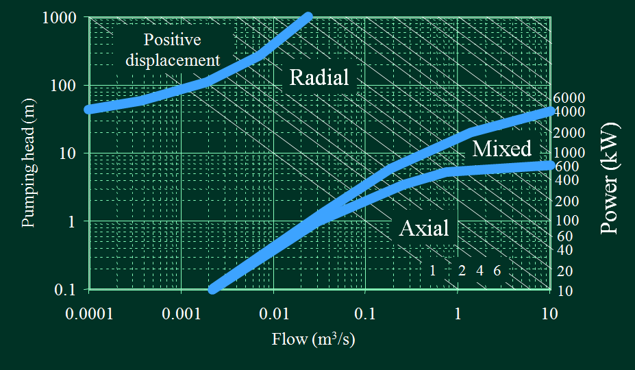 | Figure 3.2. Impeller type selection chart[2] |
In the differential agitator we will use the Four Bladed (45℃) Pitched Impeller is used to give the axial flow and it's suitable for the operation condition (power , pressure and flow rate). The prototype is in the minimum value of operation condition as shown in Figure 3.2.
3.2. Experimental work
This investigation of experimental work was carried out to maximize the performance of differential agitator by shape optimization of internal container and impeller shape. There were so many possibilities or alternatives to design the internal container of agitator to find out the best values of design parameters. Experimentation with different possibilities namely five alternatives were carried out. First, combination of external tank with one impeller was tried. Secondly, an internal container with fully opened suction and discharge ports, 100 mm X 100 mm , was introduced and experimented along with two impellers mounted axially on the shaft. In third attempt, the mutual distance between the impellers was changed from 100 mm to 240 mm and observed the result of agitation. Fourthly, keeping the mutual distance between impellers same (i.e. 100 mm), the suction and discharge ports of internal container were half closed (i.e. 100 mm X 50 mm ) and observed the result of agitation. In fifth experiment, the suction and discharge ports of the internal container were kept half closed and mutual distance between the impellers was varied from 100 mm to 240 mm and observed the result of agitation.The experimental work for impeller shape optimization was started, in which it was discovered that the small impellers caused the high radial movement of water inside the internal container and did not force the liquid to circulate through the suction and discharge ports of the internal container to outer container and deflection of impeller blades at 45 deg gave little better water circulation. Therefore, large size impeller with blades deflected at 45 deg was used to enhance the agitation process by increasing the flow rate of water for circulation in the outer tank. As a result of this experimental work, it was determined that larger impeller in all the alternatives/experiments for enhancement of agitation process be used. In these five alternatives, lime water solution has been used by adding 0.2 kg of lime quick , lump (849 kg per cubic meter density) to 62.8 kg of portable as shown in Figure 3.9. Water (1000 kg per cubic meter density) and agitate together one minutes of time. Lime water is the common name for saturated calcium hydroxide solution. It is sparsely soluble. Its chemical formula is Ca(OH)2. Since calcium hydroxide is only sparsely soluble, i.e. ca. 1.5 g per liter at 25℃, there is no visible distinction to clear water. Attentive observers will notice a slightly earthy smell. It is clearly distinguishable by the alkaline taste of the calcium hydroxide. The term lime refers to the mineral, rather than the fruit. When exposed with carbon dioxide, lime water turns into a milky solution[17]. While lime water is a clear solution, milk of lime on the other hand is a suspension of calcium hydroxide particles in water. These particles give it the milky aspect. It is commonly produced by reacting quicklime (calcium oxide) with an excess of water - usually 4 to 8 times the amount of water to the amount of quicklime. Reacting water with quicklime is sometimes referred to as "slaking" the lime. The calcium oxide will convert to the hydroxide according to the following reaction scheme :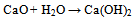 | (1) |
pH Adjustment/Coagulation - Hydrated lime is widely used to adjust the pH of water to prepare it for further treatment. Lime is also used to combat "red water" by neutralizing the acid water, thereby reducing corrosion of pipes and mains from acid waters. The corrosive waters contain excessive amounts of carbon dioxide. Lime precipitates the CO2 to form calcium carbonate, which provides a protective coating on the inside of water mains. Lime is used in conjunction with alum or iron salts for coagulating suspended solids incident to the removal of turbidity from "raw" water. It serves to maintain the proper pH for most satisfactory coagulation conditions. In some water treatment plants, alum sludge is treated with lime to facilitate sludge thickening on pressure filters.In the experimental work after finishing the agitation of lime water, a stop watch was used to read the time which was one minute, and then sample of solution was taken to read the pH by pH meter. The result gave high reading of pH, which was indicative of homogenous agitation and good mixing in this alternative. For the all alternatives, the pH reading of lime water solution was taken at three speeds 100, 200 and 300 rpm.The power for experimental work was 0.5 hp coming from 0.5 hp 1800 rpm three phase induction motor, and the variation of speed was controlled by electrical inverter.
3.3. Numerical Analysis
Finite element modeling using ANSYS11 has been used to optimize the impeller blade dimension to give the experimental result. Both experimental and theoretical analyses done to maximize performance of the differential agitator by parametric and shape optimization. The FEM using ANSYS11 was used to get the optimum design of the geometrical papmeters of the differential agitator elements while the experimental test was performed to validate the advantages of the differential agitators to give a high agitation performance of lime in the water as an example. In addition, the experimental work has been done to express the internal container shape in the agitation efficiency.
3.3.1. Agitator Geometry
Figure 2.4 shows the main parts can be considered to design the agitator. Equation (4) shows the standard relations in geometry of type and location of impeller, proportions of vessel and number of impeller blades .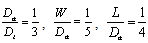 | (4) |
Where  is Impeller diameter ,
  is tank diameter , W impeller blade width and L is impeller blade length. Assume agitation geometry and speed fluid properties are tank height 0.5 m , outside tank diameter 0.4m and inside tank diameter 0.2 m.
 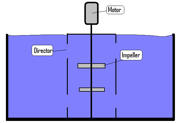 | Figure 3.4. Agitator geometry |
3.3.2. Power Calculations
Now the power can be consumed in mixing and agitation the power is a function of power number and Reynolds number which are they depending on dimensions selected: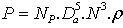 | (2) |
Where Np represents power number. ,Da represents impeller diameter (m), N represents Impeller Speed. (s-1) and ρ represents Fluid Density. (Kg/m3).In agitation process Power number is Depending on Reynolds number:Reynolds number: | (3) |
μ = Fluid viscosity N.s/m2Reynolds number was calculated for middle density 3120 kg/m3 , viscosity 9.50E-04 N.s/m2 it give 1.64E+05 Renold number.There is chart shows Relation between Reynolds number and they power number as shown in Figure 3.5.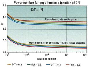 | Figure 3.5. Relation between Reynolds number and power number[18] |
From chart shown in Figure 3.5, Reynolds Number can be observed in relation to power number, like Reynolds number 1.64E+05 normally constant for the same power number increases in the range of power number from 1.3 to 1.4 In case of the Power Number is 1.4, the Power required is equal to 0.44 hp, therefore, the motor selected is 0.5 hp and Speed is 0 to 1800 rpm
3.3.3. Impeller Design
From the power of motor and speed of impeller, the external force which effect in impeller blade as tip force in the end has been calculated. Blade thickness was an obvious mechanical design consideration. The blades must be thick enough to handle fluctuating loads without bending or breaking. The following calculation takes into account the blade strength.The minimum Blade thickness can be calculated as follows: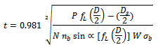 Where,
  is the location fraction for PBT equal to 0.8 , W is the width of the blade (assumed 20mm)[m],
  is Number of blades ,
  is the blade allowable stress which is equal to 83.4x10⁶ N/m2 and
  is the blade angle (assumed 45) deg .The result of blade thickness:Impeller with 3 blades: t= 3.54 mmImpeller with 4 blades: t= 4.09 mmThe problem has been solved as static problem using finite element method using ANSYS11 with this idealization, modeling was carried out with SOLIDWORK2011 and was exported to ANSYS11, which made this idealization: element type 3D Solid brick 8 node 45, number of element 4463, boundary condition fix all degree of freedom at internal surface of impeller, force is 316 N at the tip of impeller and use structural, linear, Elastic, isotropic material with 8027 kg/m3 density, 197 GPa modulus of elasticity and 0.3 poisson's ration, impeller after meshing showing in Figure 2.6. After making sure the impeller was safe for the static analysis, the optimization analysis of impeller has been done using finite element modeling using ANSYS 11 to perform the minimum weight design of impeller blade of differential agitator as shown in Figure 3.6 which the H is the thickness of impeller and W is the width of impeller.The allowable stress in the impeller is assumed to be 0.75 of yield stresses of material and the tip displacement is constrained to be no greater the 1/3000 of the blade length. FEM using ANSYS11 was made to study this case we start to model the case with following problem description:Impeller length 40 mm and tip force is 130 N, design variable are the impeller thickness (H = 4 mm) and impeller width (W = 20 mm). Objective Variables is the volume of impeller blade to be minimizing to the optimum volume. State variable are the stresses to be less than 0.75 of yield stresses of the selected Material is SS304 with yield stress equal 345 MPa which give the maximum stress to attend 258MPa. The tip displacement of blade is not greater than 1/3000 of length of impeller which is 40mm which give the maximum displacement 1.33e-5m
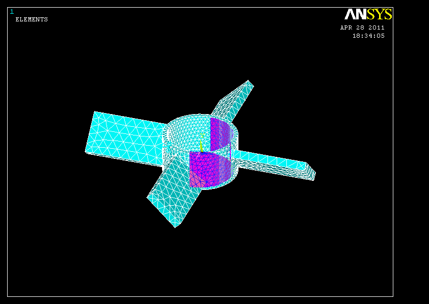 | Figure 3.6. Impeller after meshing in ANSYS |
 | Figure 3.7. Shaft boundary condition |
3.3.4. Shaft Design
Computing shaft size for both allowable shear and tensile stress depends on the rotational speed of the mixer, plus the style, diameter, power, location, and service of each impeller. For Shaft the maximum torque will occur above the uppermost impeller. The maximum torque is: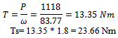 The maximum bending moment, Mmax, for the shaft is the sum of forces multiplied by the distance from the individual impellers to the bottom bearing in the mixer drive the force related to the impeller torque acting as a load at a distance related to the impeller diameter. The minimum shaft diameter for the allowable shear stress and the allowable tensile stress can be calculated as following:
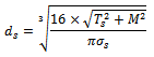
 = allowable shear stress equal 41.4x10⁶[N/m2]
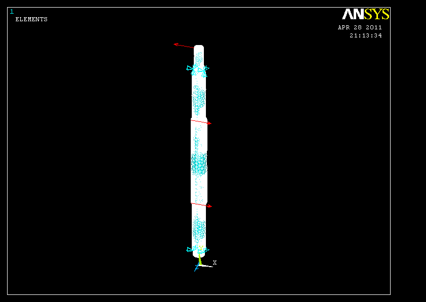
 allowable tensile stress equal 68.9x10⁶[N/m2]The result of minimum diameter: Shaft diameter for Shear stresses = 16 mmShaft diameter for tensile stresses = 28 mmKnowing the power of motor and speed of shaft, the external force which effect in shaft can be calculated. First of all the problem has been solved as a static problem using finite element method (ANSYS 11) with this idealization: element type 3D Solid brick 8 node 45, boundary condition as shown in Figure 3.16 are fix all degree of freedom at one end and fix at x and z direction only for other end, force is 316 N at impellers and motor location. The analysis time used is structural, linear, Elastic, isotropic material with 8027 kg/m3 density, 197 GPa modulus of elasticity and 0.3 poissons ration. After making sure that the shaft is safe for the static analysis the optimization analysis of shaft will be started, finite element modelling has been performed using ANSYS11 to get the minimum weight design of shaft of differential agitator as shown in Figure 3.7 where the D is the diameter of the shaft. The allowable stress in the impeller is assumed to be 0.75 of yield stresses of material and the maximum displacement is constrained to be no greater the 1/3000 of the blade length. Shaft length 500 mm and force is 316 N in impeller location and power take, design variable is the shaft diameter (D=20 mm). The objective function is the volume of shaft to be minimized to the optimum volume. The state variable is the stresses to be less than 0.75 of yield stresses for the selected material which is SS304 , with yield stress equal of 345 MPa which give the maximum stress to attain 258MPa. The maximum displacement of shaft is not greater than 1/3000 of length of shaft.
4. Result
4.1. Experimental Result
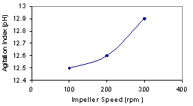
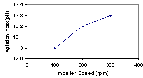
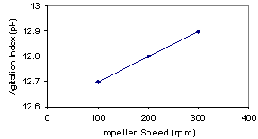
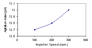
The experimental test was performed to validate the advantages of the differential agitators to give a high agitation performance of lime in the water as an example. In addition, the experimental work has been done to express the internal container shape in the agitation efficiency. For the first alternative, the experimental work was carried out at impeller speed 100, 200 and 300 rpm and take the reading of pH reading. Figure 3.1 shows the result of pH related to impeller speed in RPM. For this experiment work, it was not available to run the experiment to take measurements at 300 rpm because of high vortex inside of tank. For the second alternative the experimental work was carried out at impeller speed 100,200 and 300 rpm and take the reading of pH reading, Figure 4.2 showing the result of pH related with impeller speed (rpm) , for this experiment work the result is better than the first because of internal container was installed and avoid the high vortex causes. For the third alternative the experimental work was carried out at impeller speed 100,200 and 300 rpm and take the reading of pH reading, Figure 4.3 shows the result of pH related with impeller speed (rpm) , for this experiment work the result was homogeneous and high pH reading and gives the best result for all experimental work.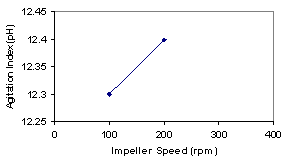 | Figure 4.1. 1st alternative experimental result |
 | Figure 4.2. 2nd alternative experimental result |
 | Figure 4.3. 3rd alternative experimental result |
 | Figure 4.4. 4th alternative experimental result |
 | Figure 4.5. 5th alternative experimental result |
For the fourth and fifth alternatives, the experimental work was also carried out at impeller speed 100, 200 and 300 rpm and the reading of pH reading is taken. Figure 4.4 and Figure 4.5 show the result of pH related to impeller speed in RPM.From the above graphs the third alternative is the best alternative to give a high agitation performance of lime in the water because the pH is the highest value and the pH reading is increased from 100 rpm to 200 rpm which is suitable with the agitation of prototype because the homogeneous agitation is showing at 200 rpm. The 200 rpm shows the best agitation index because it makes a high pH reading and also a high homogeneous motion of the water. At the same speed (i.e. 200 rpm) the saturated solution is produced by adding a quantity of lime and keep it long time in the tank after that the agitator is run at varying speed. The speed of 200 rpm gives the best suspensions of the lime solid molecules and homogeneous suspensions solid particles for all position in the tank.
4.2. Numerical Result
4.2.1. Impeller
FEM of impeller using ANSYS11 as a logical solution of static and parametric optimization to obtain the optimal volume of impeller for a maximum performance and high agitation process index.The output as shown in Figure 4.6 was the von misses stresses which was 26 MPa as maximum value. The maximum von misses stress was in the root of impeller and the maximum deflection of the impeller blade is 0.02 mm in the tip of blade as shown in Figure 4.7. The stress and the deformation were safe.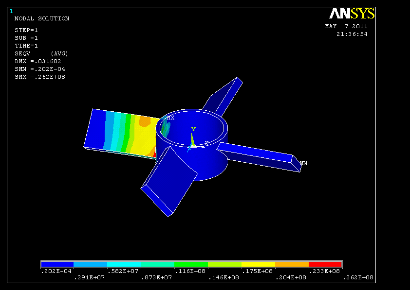 | Figure 4.6. Von misses stresses in impeller |
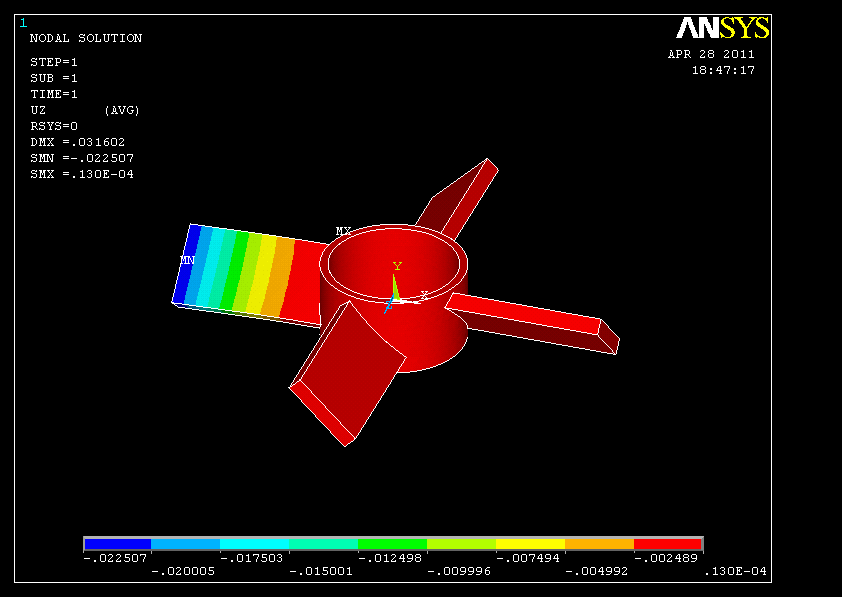 | Figure 4.7. Tip displacement for impeller blade |
For the optimization process, the result has been shown in Figure 4.8. That optimum blade thickness W is 2.9 mm and the optimum blade width is 14.6 mm.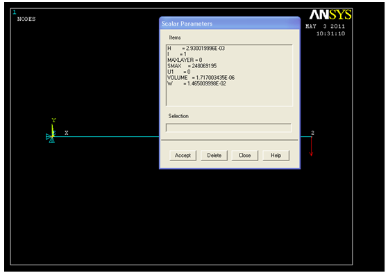 | Figure 4.8. Impeller blade scalar parameters after optimization |
ANSYS optimization solution gives the history of design variables during the iteration, the blade thickness, which is changed from 4mm to 2.9mm to give the maximum stresses and deflection which are safe (see Figure 4.9).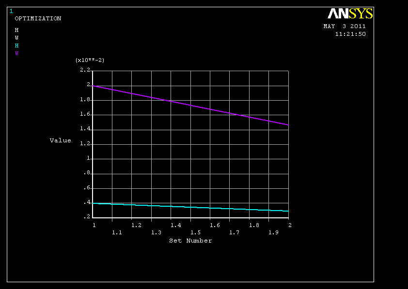 | Figure 4.9. Design variable history |
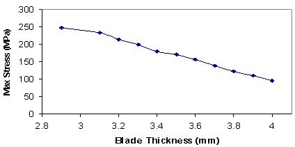 | Figure 4.10. Relation between blade thickness and stresses |
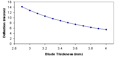 | Figure 4.11. Relation between blade thickness and deflection |
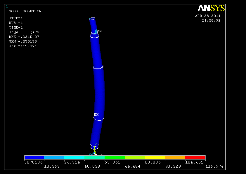 | Figure 4.12. Von misses stresses in shaft |
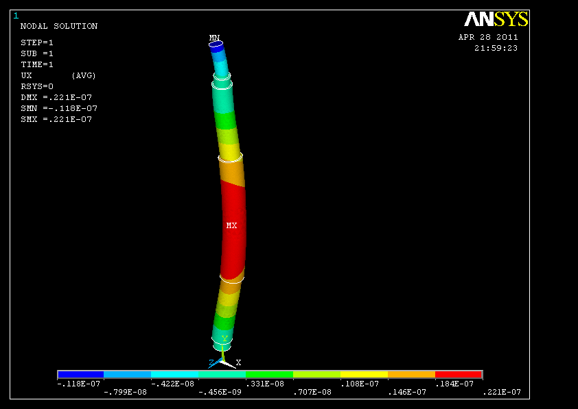 | Figure 4.13. Deflection in shaft |
Impeller blade thickness is the main factor for the blade optimization, change in the blade thickness leads to change the stresses as shown in Figure 4.10 while Figure 4.11 shows the relation between the blade thickness and the deflection.
4.2.2. Shaft
For the static analysis the maximum stress is 120 Pa and maximum deflection is 0.02 mm which is safe as shown in Figure 4.12 and Figure 4.13.
5. Discussion
It has been simulated that the internal container shape and impeller blade thickness would be subjected to the fluid force and power transmission force. Experimental work and FEM have been applied to calculate the optimal shape of the internal container and optimal thickness of the impeller blade. The experimental work has been done to express the internal container shape in the agitation efficiency. The internal container intakes (suction and discharge) has been changed the shape and express the result by pH reading. For all experimental investigations, by repeating the lap test with new shape of internal container intakes (suction and discharge), it has been found that the optimal shape design of internal container intakes (suction and discharge) is the full intake area because it gives the high flow rate. For all experimental investigation, by repeating the lap test with new impeller angle and size, it has been found that the optimal impeller angle is 45 degree because it gives the high suction and discharge of flow through the internal container. It has been figured out that the optimal dimensions of impeller are when the gap between the impeller tip and the internal container surface is minimum because it forces the flow to motion in the axial flow direction and no more flow can escape between the impeller and internal container. The normalized principal stress which has been calculated by ANSYS11 during the change of impeller blade thickness, has been used to express the change in the impeller blade thickness with the stress. For all the dimensions investigated, by repeating the optimization loop many times, in each loop the impeller blade thickness is changed and the stress in the root of impeller is calculated until the optimal impeller blade thickness to get the minimum volume of impeller. It has been shown that the impeller blade thickness can be minimized to 2.9 mm to carry out the allowable stress, and the volume of impeller blade was minimized to 46% from the original volume.
6. Conclusions
The experimental work and FEM ANSYS11 package with optimization technique have been used to investigate the parametric and shape optimization of the differential agitator to maximize its performance. The investigations have been made for the two types of agitators, i.e. normal agitator and differential agitator. These investigations have shown that in the normal agitator the experimental test can not completed due to high vortex in the fluid which starts highly from 150 rpm speed of the impeller. Normal agitator cause vortex in the center of the liquid the matter that enforces the manufacturers to put Baffles inside the agitating tanks that leads to agitator defect like bubbles, cavitations and lowering the agitating efficiency. The differential agitator avoids the vortex forming in the liquid and gives a high homogeneous motion of the liquid due to transferring the vortex from the outer tank to internal container. The optimal shape of the internal container is the full open suction and discharge intakes. The optimal location of impeller is 130mm from the top for upper impeller and 130mm from bottom for lower impeller. The optimal impeller is 4BPT 45 impeller. In addition, the optimal speed for the prototype is 200 rpm because it gives the high agitation index pH and homogenous motion of the liquid.
References
| [1] | Asiri, Saeed, “Differential Agitator”, KACST patent, No. 06270232, (2010). |
| [2] | Polasek P and MUTL "Acceleration of gravity separation process. Proc. Filtech Europa - Int. Conf. on Filtration and Separation Technology". October, Düsseldorf, Germany (2003). |
| [3] | Weber Arthur P, "Continuous flow reactor for high viscosity material" betiilellem steel corp, (1977). |
| [4] | Weetman Ronald J and Howk Richad A, " Mixer for axial flow on a non uniform flow field" gen signal corp US (1988). |
| [5] | Inoue Takao and Saito Makoto, "mixing device and method" kajima corp JP (1999). |
| [6] | Hockmeyer and Herman H, "Apparatus for dispersing solid constituents into a liquid" hockmeyer equipment corp. (2006). |
| [7] | Hereit F, Mutl S and Vagner V "The formation of separable suspensions and the methods of its assessment". Proc. Int. Conf. IWA. Paris, France. 0095-0099. (1983). |
| [8] | Yinyu Hu, Zhe Liu, Jichu Yang, Yong Jin and Yi Cheng , "Millisecond mixing of liquids using a novel jet nozzle, Department of Chemical Engineering", Tsinghua University, Beijing 100084, PR China, November (2008). |
| [9] | Richard V. Calabrese, Michael K. Francis,Ved P. Mishra and Supathom Phongikaroon ,"Measurement and Analysis of Drop Size in a Batch Rotor Stator Mixer" University of Maryland , MD 20742-2111 USA (2011). |
| [10] | Mitsuaki Funakoshi , "Chaotic mixing and mixing efficiency in a short time" , Department of Applied Analysis and Complex Dynamical Systems, Graduate School of Informatics, Kyoto University, Yoshida-Honmachi, Sakyo- ku, Kyoto 606-8501, Japan , May (2007). |
| [11] | Simo Siiriä , and Jouko Yliruusia , "Determining a value for mixing: Mixing degree" , University of Helsinki, Division of Pharmaceutical Technology, Finland , August (2009). |
| [12] | Polasek P and Mutl S "Acceleration of gravity separation process". J. Filtr. 5 (1) 33-39 (2005). |
| [13] | Samaras, K.; Mavros, P.; Zamboulis, D. "Effect of continuous feed stream and agitator type on CFSTR mixing state". Ind. Eng. Chem. Res. (2006). |
| [14] | F. Moretti, D. Melideo, F. D’Auria, "CFX simulations of ROCOM experiments", TACIS Project R2.02/02, Working Document TP-08-01(06), December (2006). |
| [15] | C. Leguay, G. Ozcan Taskin and C. D. Rielly "Gas liquid mass transfer in a vortex ingesting, agitated draft tube reactor" University of Cambridge CB2 3RA UK (2011). |
| [16] | Edwards, Robert. “Liquid Extraction”, Laboratory Handout, Case Western Reserve University, Aug. (2006). |
| [17] | A. Seidell, W. F. Linke, Van Nostrand "Solubility of Inorganic and Metalorganic Compounds - A Compilation of Solubility Data from the Periodical Literature" Publisher, (2006). |
| [18] | D. S. Dickey and J. B. Fasano " Mechanical Design of Mixing equipment" ,(2004). |
| [19] | Kropf, Keith, "Rotating/tipping agitator for a washing machine", US Patent 7013517, March (2006). |
| [20] | ANSYS11 Software program, ©Ansys, Inc., Canonsburg, PA USA, (2011). |
 Abstract
 Reference
 Full-Text PDF
 Full-Text HTML