-
Paper Information
- Next Paper
- Paper Submission
-
Journal Information
- About This Journal
- Editorial Board
- Current Issue
- Archive
- Author Guidelines
- Contact Us
International Journal of Mechanics and Applications
p-ISSN: 2165-9281 e-ISSN: 2165-9303
2012; 2(5): 49-60
doi: 10.5923/j.mechanics.20120205.01
Knowledge Based Simulation Driven Design for Crash Applications
 Abstract
 Reference
 Full-Text PDF
 Full-Text HTML
J. Badin 1, 2, D. Chamoret 1, S. Roth 1, J. R. Imbert 2, S. Gomes 1
1IRTES-M3M, University of Technology, UTBM, 90010, Belfort Cedex, France
2DPS - Digital Product Simulation, Espace Claude Monet, 2-4 rue Hans List, 78290, Croissy- sur- Seine, France
Correspondence to: J. Badin , IRTES-M3M, University of Technology, UTBM, 90010, Belfort Cedex, France.
| Email: |  |
Copyright © 2012 Scientific & Academic Publishing. All Rights Reserved.
This paper focuses on industrial design and crash simulation. Indeed, crash simulation has progressed considerably to become a key area in product design, especially in automotive industry. The main objective of this paper is to show the role of the numerical simulation on the design process and to explain its integration in this process. Actually, we can now talk about a strong connection between the simulation and the design process. It allows significant gains, however it highlights the problem of collaboration around knowledge in the design process. Indeed, each expert model is driven by specific data which are shared by several users and used at the same time in a concurrent engineering context. Thus in this paper, we propose at first an assess of differents kind of crash simulation integration on design process and their benefits/limits. Then we propose an approach referred to as KCM – Knowledge Configuration Management, based on management of fine granularity knowledge in configuration. This approach is likely to improve collaboration between project participants, improving capitalization, traceability, reuse and consistency of the knowledge used simultaneously on several activities in parallel within the design process. Finally, the purpose of our paper is to find new ways to further optimize the simulation/Design integration through an approach of knowledge management which is a new challenge today in industry.
Keywords: Crash, Simulation Design Process, Concurrent Engineering, Knowledge Management
Article Outline
1. Introduction
- Although the design process has evolved, the numerical simulation has also progressed considerably to become a key area in product design. Initially used at the end of the design process as validation or presentation of activities, simulation is currently used in the overall design process and especially in the upstream phase (trade-off, pre-design) using CAD-CAE integration and parametric models to drive the design and identify the better concepts of product’s architecture earlier. Thus, nowadays, it seems as necessary to use numerical simulation, especially the finite element simulation to lead the way to innovation [1-2]. In the early design phases, numerical simulation allows for the management of a better design and quicker. This is particularly true in the area of mechanical systems more specifically in the automotive industry where the development speed has to be increased. That is the reason why the crash simulation techniques are gaining an increasing role in the product development instead of time-consuming validation testing.These evolutions have led to a strong connexion between the design process and the numerical simulation and today we talk about “simulation driven design method” (Figure 1).. In this way it helps to streamline the design process, and to better take into account the constraints from the various expert domains in the product design and a better control.Indeed, the idea is to minimize physical prototypes which are very expensive to make and use the simulation even for the certification. Thus one of classical objective in automotive industry for future is to produce a car with just one prototype good at the first time.
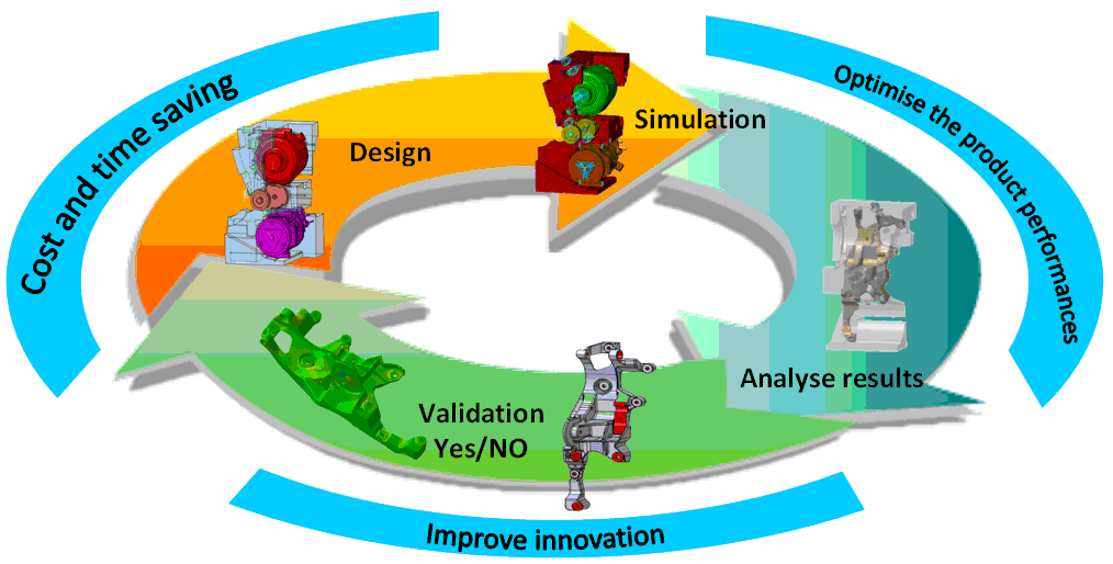 | Figure 1. Using numerical simulation overall the design process (Simulation Driven Design) |
2. Numerical Simulation in the Design Process
2.1. Evolution of the Product Design
- Within the current economical and industrial context, companies would like to obtain a better cost control and to streamline their product design in order to reach the famous “cost/quality/delay” objectives [4-5-6]. It involves the development of new methods [7] in design process with the enhancement of concurrent engineering contexts [8-9]. The engineering process is a set of interlinked activities and involving many actors in different areas of expertise but dependent on each other. The design process is an activity of the engineering process which is absolutely essential in the product lifecycle (AFNOR, 1994). In the context of minimizing design time and parallelism of the activities of the design process, industrial practices have evolved from engineering process divided into sequences or phases [10] to a concurrent engineering or integrated engineering process (Figure 2). These concurrent design methods aim to enhance collaborative work in order to increase the responsiveness of the company to reduce costs. They are realized by a parallel design activities and the enhancement of collaborative sharing of data between resources and actors in the company. Design process evolutions were followed by new design method and nowadays, with the use of 3D geometrical product components in CAD files, engineers include parameters and expert rules (considering as knowledge) to drive the geometry in CAD models through parametric and variational approaches [11] (Figure 3).
 | Figure 2. concurrent engineering approach for time saving in the design process |
 | Figure 3. parametric design method on an automotive Power Unit |
2.2. Simulation Driven Design
- Numerical simulation driven design leads to many heterogeneous computational models which interact with each other. Indeed there exist a gap between designers and analysts. The large number of heterogeneous information handled in the design process combined with the low level of interconnection between CAD and crash simulation software tools often lead to data discrepancy and incoherence [14]. Thus, the data and information are often scattered and duplicated, thus preventing data coherence, traceability, and reuse, and inhibiting the respect of design steps sequences. This situation prevents companies from turning the information and know-how embedded in their geometric and simulation models into a shared structured knowledge that can be capitalized. Different kinds of approaches exist nowadays to facilitate this connexion between the design process and the use of numerical simulation. Overall, these approaches try to develop the integration design / simulation in a collaborative environment.
 | Figure 4. CAD-CAE integration process |
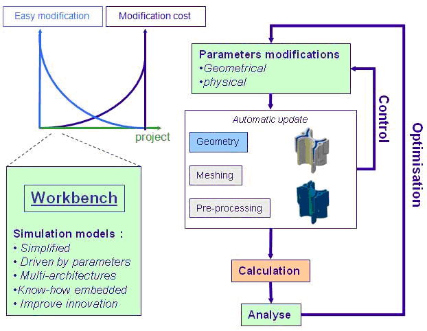 | Figure 5. workbench process (PSA Peugeot Citroën example) |
2.3. Benefit of design/simulation integration
- The interests to bring closer together the design and the simulation are multiples and they can be grouped into three main parts:The first one concerns the improvement of collaborative work, tractability and coherence between design and simulation activities. Today engineers work on concurrent engineering context which mean they need to share an important volume of information in heterogeneous design and simulation activities. Each activity may takes place in different site using a large range of tools which are not able to communicate together. If design and simulation are totally independent and unsynchronised it is very difficult to take account of update in a model which impacts other models. The aim is to gather engineers on a collaborative model or a common tool which guaranteed the link between design and simulation and allowing better performances for traceability and coherence. Thus, design and simulation integration, improve collaborative work in a project. The second one deals with the reducing of routine design and how to better take into account of constraint from several areas of expertises. Link design and simulation allow for better take into account of constraint from several areas of expertises. With parametric models (using the associativity), the constraints from geometric design are faster take into account in the simulation process, and reverses, which mean simulation results can impact the design and drive it. Well, it is easier to make loops between design and simulation and validate concepts by the simulation. For example, with classical method we use design tool for component modelling and then specifics simulation tools for meshing, pre-processing, calculation, post-processing for the first design concept tested, and then it is necessary to start again for the next design modification. It takes very long time and engineers cannot test numerous product architecture. With a design/simulation integration method it is possible to reduce the routine design several times (4 times and more) start for the second loop of modification (Figure 6). This method carried out to earn in quality because engineers can test a large range of product design and identify the better, and limit the time consuming.The last one concerns a better control in the design and the simulation activities which allow streamlining of the design process. Simulation groups several complexes activities which need experts to use specifics tools. With design/simulation integration, automatics processes used allow for designers to use the simulation with low level of knowledge in simulation. Also, it allows for capitalizing and secure know-how (simulation process, constraints, etc.) into models and thus streamlines the design process. If design/simulation integration is now commonly used by industrials and offers significant gains in performance in the design process, some domain has particularity as crash. These particularities come from the size of the design and simulation model handled and the specific design context of crash activities.
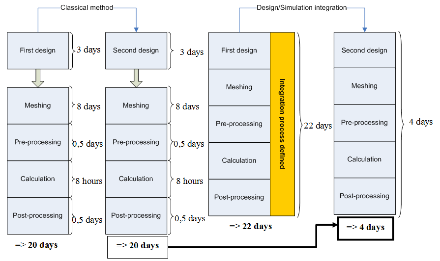 | Figure 6. classical method vs design/simulation integration |
3. Several Industrial Methods for CAD-CEA Integration
- It’s now possible to deploy some approaches based on strong links between geometries and FEA components. Unfortunately in these cases, body shapes have to be simplified. Most of the time, these kinds of approaches are used at the very early stage of a new project. This lat point made these approaches very interesting. Thanks to the strong link between CAD geometries and FEA, and because geometries are simplified, meshing operations can be performed using automatic mesher. The link between CAD & FEA, the high level of automation makes short loops iteration possible.
3.1. AVP: an example Based on Skeleton and Simplified Geometry
- Within four weeks (Figure 7), a new body style can be defined. The whole structure product is divided into hollows parts, junctions and panels. Generally this kind of approach is very efficient during early design phases. It proposes an agile geometry, able to represent several architectures. But when the car concept becomes mature, engineers need to design more and more precisely. Although geometries are parametric, they cannot evolve to more detailed geometries. That is the big limitation of the approach.
3.2. Fast Concept Modeller: an Example Based on Productive Design Tools
- FCM is a set of tools aiming at helping designers to create very quickly and easily vehicle geometries. Based on very productive tools, FCM allows users to model a vehicle manipulating geometry objects directly on the screen. Fast Concept Modeller is a single CATIA V5 workbench. The user interface favours “free hand” actions. The geometries results, as they were with the AVP approach, are parametric and very simplified. During the new project vehicle geometries can become more and more detailed. They can evolve from a beam model to a more complex beam-shell model including fillets, multi-flanges, etc. Regarding the FEM functions included in the software, shell can be mesh using batch meshing technique (ANSA). In that case properties and connexions attributes defined on geometry are directly transferred on finite element model. For the early stage of the process Beams are used. In that case, the car geometry is automatically discretized using variable cross section beams. This process is very powerful if optimization loops are engage on the beam structure. FCM can pilot the vehicle geometry from the result of such an optimisation.
3.3. Approach Using Software of the Shelf
- Powerful pre-processing software fully integrated into CATIA V5 exists and allow expert simulations set-up (Figure 8). These software lies on the CATIA V5 philosophy (all the model features have geometry support), but also extend the natural capability of CATIA V5 providing the user with direct access to nodes & elements. Such as FCM, these kinds of software offer batch meshing capabilities. This possibility bridges the gap in the CATIA mesher. In this way geometry model can be much more detailed. In another hand, the possibility to deal directly with nodes & elements entities brings user the change to handle orphan mesh. Meshes perform with more dedicated software or meshes of a previous project can be easily used.
4. Limitations and Opening of Crash Integration
4.1. Detailed Geometries
- As we mentioned above, the approaches based on a strong link between FEM and geometry imply - most of the time - a poor level of detail in geometry: the simplest geometry is, the more automated the update on changes will be. The gap between simple and detailed geometries is not easy to fill. Even if during the early design phases geometries have to be very simple in order to be able to evaluate a lot of architectures and alternatives, while the project run engineers need to study the influence of small modifications. Teams, quickly have to integrate manufacturing process parameters. Unfortunately, it is difficult to use these highly simplified models for the following design steps.. Moreover, CAD-CAE integrated approaches embed geometries, meshes and analysis features, the associated numerical models are quite big and require the use of powerful workstation.
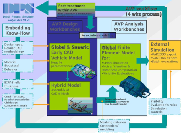 | Figure 7. AVP Workflow |
 | Figure 8. specific Crash Analysis Features within CATIA V5 |
4.2. Integrated Approaches = CAD + CAE
- For an organisation, saying that the same team will handle geometry & FEM models, is a big challenge. It means FEA engineers have to be trained in CAD software, (more rarely, Designers are trained in simulation). The FEA engineer job is changing slowly... Double competency, Design + Simulation, will be on tomorrow a must have for young engineers.
4.3. Simulation Life Cycle Management
- With the natural trend bringing closer CAD and FEA, some techniques now enter in the simulation field. Among them SLM, Simulation Life Cycle Management [15] is surely something which will become more and more important. Designers and Simulation engineers are now working together. They need to share the same data. They will need some specific tools to do that more easily.
4.4. Optimisation and More
- Probably the main advantage of a CAD-CAE integration is the fact that organisation can perform short loop of iteration. On each change the remaining work is automatically update then performed. Optimisation is possible and even effective for more and more complex cases. The next challenge will be the coupling between several types of simulations. Being able to take into account the forging or stamping process of each part during the crash worthiness simulation is a big challenge, but will ensure an important level of accuracy.
4.5. Knowledge Management for Design and Simulation
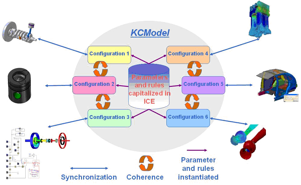
- We have seen design/simulation integrations method focused on models closer, but problems still exists about knowledge embedded in models [16]. Indeed, each expert model manages parameters and rules independently from other model which uses the same knowledge. This knowledge is often duplicated and dependant of the models which using it. This situation favours knowledge inconsistency between models and it often happens that simulations are launched on different models sharing same parameter but on wrong values. Indeed it is very difficult to make expert models communicate together because they are used with several tools which are not able to communicate together despite CAD-CAE integration method. It appears that is their no communication platform for this type of knowledge and today with the massive using of design and simulation models it is a real problematic.Nowadays, researches are focused on this problematic in accordance with global PLM (Product Life Cycle Management) [17-18] approach. The aim is to define a method and a model or meta-model (in UML or MOF which are modelling standards defined by OMG)(UML: Unified Modelling Language is a language used to formalise model object oriented. UML is defined by OMG. OMG : Object Management Group – www.omg.org, MOF: Meta Object facility is a language used to formalise meta-models object oriented. MOF is defined by OMG.) allowing to manage knowledge and share it through experts models with consistency. Some of research work proposes to capitalize parameters and rules extracted forms design and simulation models into generic information baseline and to built knowledge configuration synchronized with experts models. We propose to explain one of these researches called KCModel.
4.6. Perspectives with KCModel (Knowledge Configuration Model)
- The aim of this research is to propose a new tool which helps users to ensure data, information, and knowledge consistency when shared in several and heterogeneous experts CAD and CAE models. This tool will focus on a new generic approach called KCModel: “Knowledge Configuration Model” based on knowledge configurations synchronized with expert models [14]. KCModel is formalized into meta-models in UML Language In the context of KCModel, we consider as:• technical data, the parameters and expert rules extracted from experts models,• information, the data capitalized on, structured and organized into a specific entity to construct a technical and generic product information baseline,• knowledge, a set of technical product information entities instantiated from the baseline in a configuration used in specific design or simulation activity. This configuration is synchronized with a specific CAD or CAE model.The purpose of the KCModel is to Capitalize, Trace, Re-use, and ensure the Consistency (CTRC) of technical data shared by several experts model, especially in the upstream step of design process (Figure 9):1. Capitalize on parameter and rules as a generic and cross functional baseline2. Share and trace through several users3. Re-use parameters and rules in expert models.4. Ensure the consistency and save the modifications
 | Figure 9. global KCModel method |
 | Figure 10. using knowledge configuration in KCModel to ensure the consistency between expert models |
5. Crashworthiness Finite Element Simulations Overview
- Compared to other kind of simulations, such as structural or vibration analysis, crash analysis has got some typical characteristics we may speak about. We can start our discussion dealing with the fact that all the carmakers around the world decided some years ago to reduce their need for physical prototypes. It's seems very difficult at that time to believe we can avoid real vehicle experiments regarding crash. But it's one of their objectives. The exploration of computational methods in crashworthiness applications are involved in recent works dealing with vehicle impact numerical simulation, or dynamic biomechanical simulations [20-23]. Principles of numerical computations are the same for all these topics. However the paper will focus on vehicle crashworthiness in order to give an industrial point of view of impact simulation in the design process.
5.1. Industrial Context
5.1.1. Complexity of the Model
- The first aspect that appears when reviewing FEA models for crash is the complexity of such models. Most of the time crash models embed hundred of parts, from main body panels to small hinge. They embed visible parts, (wheels) and none visible ones, (outer CV joint). Models include heavy parts, (battery) but also light, (foam), etc. Because crash analysis is mainly a problem of intrusion of one part in another, geometries are often modelled as close as possible of their reality. Shapes are often very complex. The facts that models include a lot of parts imply that the connections between these parts must be defined. In reality parts and components are assemble using welding, (seam welding and spot welding); using bolt and even (more and more) glue. Thus, in addition to include hundred of parts, the FEA model for crash will also need thousand of connections definitions, thousand of connection properties definitions, (fracture limits, etc.). Designing vehicle body does not really depend on routine design but there is a strong impact on several other parts of the cars as the power unit, the cockpit, the frame, etc.
5.1.2. Size of the Model
- Hundred of parts, thousand of connections, millions of nodes: huge problem in terms of DOF. Because of the size of the problem and because of the transient aspect of the simulation, the computation phase of a crashworthiness analysis can last several days. Each year, even if the power of computer increases the duration of a typical crash computation remains the same. Engineers are not yet in the process of stabilizing their models. They enrich them with more and more detailed parts, with finer meshes, with more precise contact management, etc. This way the computer power is harnessed to serve the quality of results instead of reducing computing time. The big size of crash simulation models unfortunately also deals with the difficulties to manipulate these complex models during the pre-processing and post processing phases. These phases are also very demanding in terms of PC power regarding crash simulations.
5.1.3. Marketing Aspects
- Whereas some years ago the car-style was so important for final customers, the crashworthiness aspect appears more and more as a key point in the choice for a new vehicle. Nowadays it is not uncommon to have some information regarding the Euro NCAP results of a new car directly in the advertisements for this new car; nor to see crash test dummy “playing” in such advertising. Priority between Style and Crashworthiness has changes these few last years. Thus crash as a strong impact on product design cost and that is the reason why industrials show an important interest and make research or developments.
5.2. Finite Element Simulation of Crash
- Finite element analysis of crash is among the most challenging nonlinear problems in structural mechanics [24]. This kind of problems leads to large strains and rotations with contact among the various components of the studied structures. The deformation also involves wave effects, associated with high stresses. This is accompanied by inertial effects. The finite element method consists in solving numerically a nonlinear partial differential equations system of motion in space-time domain coupled with constitutive laws and appropriate boundary conditions. First, the partial differential equations problems with boundary conditions are reformulated in a weak form assuming an admissible displacement. The, the spatial discretization leads to set of algebraic equations time dependant for crash problems. This set of second order differential equations in time is then solved by discretization in the time domain. For the simulation of dynamic problems such as crash analysis, the time discretization is one of the major points that can strongly influence the accuracy and efficiency of the algorithm. The two main solution procedures are the explicit and implicit algorithms. The implicit scheme is unconditionally stable. But it has two main drawbacks: the first one is that a linear set of equations must be solved repeatedly so the computation time increases with the size of the model when using a direct solver. The second one concerns convergence which is sometimes hard to reach. In general finite element code dedicated to the simulation of transient dynamic phenomena such as crash or impact (e.g. Radioss, Altair Hyperworks, Michigan, USA), the temporal explicit scheme is used. Explicit numerical time schemes such as the well-known central difference scheme have been widely used as they do not require numerical iterations at each time step, and also for their good properties in term of accuracy and robustness with possible nonlinearities. The state of the system is evaluated at each time step. The state at a given time t, is used to calculate the state at the time
 where
where  is representing the time step. Furthermore, the inertia and mass of the system are taken into account. The explicit scheme is a specific method where the equilibrium state is evaluated at a time where displacements are already known at each point of the mesh. In this process, displacements are known at the time where the dynamic equilibrium of the system is solved, and needs only the inversion of the mass matrix. Furthermore, if a lumped mass matrix scheme is used, the mass matrix is diagonal and does not need inversion. The resolution of the system is very quick since each degree of freedom is calculated separately. Each stress is evaluated in each element individually. At each time step, the state of equilibrium is updated, which corresponds to the propagation of a wave into the element. This important point leads to the conditional stability of the scheme, which means the existence of a critical time step for the stability of the resolution. For high speed simulations, temporal discretization can be performed by the central difference methods (CDM). In such explicit time integration method, specific conditions on the maximal time step for numerical stability are assumed. This time step also depends on the number and the type of elements used to model the system. In automotive industry, FE models are developed using 4 nodes shell elements [25]. This requirement means that, during one time step, the distance travelled by the fastest wave in the model should be smaller than the smallest characteristic element size in the mesh, representing the shortest length for a wave arriving on a node to cross the element. For example, with elements of 5 mm, and for a typical steel material law, this condition leads to an order of magnitude of 10-3 ms. Indeed with this order of magnitude of the time step, it appears that this specific scheme is an appropriate method to solve very rapid phenomenon, with high velocity leading to non highly non linear problems. For typical impact duration of 100-200 ms, it appears necessary to use this kind of integration scheme for an accuracy of the results. This time step also depends on the number and the type of elements used to model the system. In automotive industry, FE models are developed using 4 nodes shell elements (BELYTSCHKO, T.; TSAY, C.S., 1981). The following picture illustrates a FE model of a window, developed with shell elements.
 6. Interconnection Design/Crash Using Knowledge Configuration Management: An Example
- In this section we discuss about an example of crash simulation integration in the design process using collaborative approach. Indeed, the SIA trophy is an automotive challenge for automotive designers, manufacturers, universities, whose aim is to build and design a vehicle able to face to today’s new specifications in terms of innovations, respect of the environment. The main idea in UTBM Team is to be able to design a new a vehicle each year using the knowledge capitalised by the previous teams. Teams are composed of students, thus each year the turnover of the team is 100% off. In this context, the concept of Knowledge management, using KCModel, for design and simulation of crash is appeared like well appropriated. Thus, as specified in section 1, numerical simulation has been used throughout the design process: trade-off, pre-sizing and sizing. Different types of finite element analysis were done to design the new vehicle (thermal analysis, acoustic, etc.) and were exploited at the same time in a concurrent design context. Figure 11 illustrates this interconnection and more especially the pre-sizing phase to illustrate collaboration and impacts between the expert domains. Thus, for each expert domain, CAD-CAE integration (used in early design stage) allows to improve the new design choices through short loops of design and simulation process.For example, new frame design was test in simulation and analysis results allow giving design recommendations. Nevertheless, each expert domain used heterogeneous design and simulation tools and need to share parameters and constraint (mathematic relations, boundary conditions, etc.). Consequently, they use knowledge configurations management method to check conflicts and to control the impact of each design choices on the others expert domains. For example, cylinder block model (expert domain 1) needs to share parameters with frame model (expert domain 3) and they have to be sure that design choices of each of them do not generate conflicts in the design process. The finite element simulation of crash is introduced in the expert domain 3. The simulation was performed to design the body and the frame of the new vehicle. CAD geometry models (Figure 11) have been used to generate the mesh. The bodywork and the frame of the vehicle have been modelled with solid parts into CAD software, in taking into account their thickness. Mid-surfaces of the bodywork and of the frame have been extracted in order to mesh them with 4 nodes shell elements as recommended for a crash FEA, and illustrated in Figure 11.In this experiment, the use of knowledge configuration into several loop of design and simulation models, allows to better take into account of constraints and improve collaboration. It also helps to better consider every technical choice from each expert area despite their heterogeneity and diversity and avoid conflict in the design process that can result in lost time, increased cost and lower product quality.
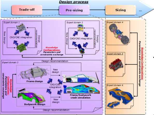 | Figure 11. CAD-CAE integration using knowledge management approach |
 | Figure 12. synoptic representation of this research work |
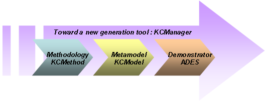
7. Conclusions
- The main objective was to underline the strong interconnection between a specific type of numerical simulation – crash - , and the design process especially in very complex field the automotive design. It concerns the appearance of a vehicle, governed by important kinds of parameters factors including security, safety and engineering - all of which have their own set of specialists. In this context, an approach to manage knowledge using configurations synchronized with expert models which enable designers to use parameters consistently in a collaborative context seems to be necessary. This kind of approach can substantially reduce development time and costs. About our knowledge management work, the main results of our research are structured around three axes (Figure 12) :• A methodology for knowledge configuration management qualified as KCMethod.• A meta-model, called KCModel, structuring concepts manipulated by KCMethod.• A model of feasibility, namely ADES software tool, allowing testing and validation our approach.The overall results are articulated around a next-generation software solution, described as KCManager, in order to deploy the approach proposed in Figure 2 across the company.The KCModel and the presentation/experiment of ADES will be presented in a next paper.