Alexander Gmiterko , Michal Kelemen , Ivan Virgala
Department of applied mechanics and mechatronics, Faculty of mechanical engineering / Technical university of Kosice, Kosice, 04200, Slovakia
Correspondence to: Ivan Virgala , Department of applied mechanics and mechatronics, Faculty of mechanical engineering / Technical university of Kosice, Kosice, 04200, Slovakia.
| Email: |  |
Copyright © 2012 Scientific & Academic Publishing. All Rights Reserved.
Abstract
The paper deals with N-mass system imitating snake rectilinear motion. At first the snake rectilinear motion is described from the view of biology. For engineering analyse the snake body have to be replaced with many same segments which we will call masses. The whole snake motion is based on friction forces between snake body and surface on which the snake locomotes. Because of this the different kind of friction models are discussed. In the next section rectilinear motion is modelled with Coulomb friction model and the conditions of motion are described. After determination of propulsive and external forces the one motion phase time is determined. From this we can establish average velocity equation for N-mass moving system. At last the optimal number of masses N is determined and the average velocity dependence on number of masses N for different angles of surface incline in the graph is shown.
Keywords:
Friction, Locomotion, N-Mass System, Rectilinear, Snake
1. Introduction
The biologically inspired snake-like robots are able to perform a stable motion in areas where other kinds of mechanisms are ineffective or not very stable. Their locomotion is on very high level of stability because of that most parts of their body are in contact with the surface on which they locomote. The snake-like robots are usually composed from many same segments. On the one hand their body structure enables them to perform a lot of desired functions. On the other hand their structure is difficult from the view of control.A rectilinear motion is one of the four basic biological snake locomotion modes. This pattern gait is usually used by the snakes with heavy bodies which are not able to move by undulation. This kind of motion is not very effective but it is usable in environments where gait as lateral undulation or sidewinding are not suitable because of their high amplitudes of yaw. In practice applications there are often necessary mechanisms which can move through the hard to reach areas, narrow spaces or man dangerous environments. In some situations may be used rectilinear locomotion of a snake-like robot to achieve desired objects.[1]There are not many functional models concerning the rectilinear motion. Most works are done only in theoretical level. For motion variables determination there were usedvarious kinds of mathematical models. Within this study the model consists only of identical masses will be considered. There will not be considered passive bonds between the masses only the linear actuators.At first the paper deals with biological analysis of snake rectilinear motion. Further, static friction model, Coulomb friction model, viscous friction model and Stribeck effect are discussed in order to describing friction between snake and surface for consistent modelling. The mechanical system investigated in this paper will obey isotropic Coulomb friction model. In the next section the mathematical model of snake rectilinear motion is established. By means of Newton´s dynamics the external forces affecting i-th mass are described and subsequently the average velocity of the N-mass system is derived. In order to achieve the maximum velocity the optimal number of masses N is derived. The average velocity dependence on number of masses N for different angles of surface incline in the graph is shown.
2. Biological Snake Motion
The rectilinear motion is the second basic motion of snake locomotion and it absolutely differs from other ways of the motion. The rectilinear motion is specific for the snakes with heavy body disabling their side undulation. This type of motion is slower than other ones. The ventral surface is used for providing the drive through the anchoring. During the motion ventral scales are alternately smoothly lifting up from the surface and drawing forward and then lowering down. The part of ventral skin is drawing forward and so the scales are joining in the bunch. This part of the body is then pushing down and the sides of abdomen go down on the surface. This motion enables the snakes going straight. So that to enable this mode of motion the snakes fixes several points of longitudinal lower part and moves the body parts among them. The points are called as static or fixed points. The propulsive force of the snake is primary the friction force and it is the force between the snake and the surface. In contrast with sidewinding motion and lateral undulation motion including the unilateral muscle activity changing from one side to another, the rectilinear motion includes a bilateral activity of the muscles joining the skin with the skeleton. On the Figure 1 the snake rectilinear motion is shown.[1][2][3] | Figure 1. The snake rectilinear motion |
3. Friction Models
A friction in the mechanical parts of the moving systems causes failures especially during precise position regulation. Its compensation can be reaches by design solutions however they not eliminate friction course nonlinearity within low velocities. Within this study a friction is necessary in order to mechanism motion. The motion of i-th mass is based on the friction of other masses. In the next section we will discuss static friction model, Coulomb and viscous friction model and Stribeck effect.[4]
3.1. Static Friction Model
This kind of friction occurs if a mass velocity equals zero and it acts against a relative mass motion. | (1) |
 | (2) |
Where fS and FN are static friction coefficient and normal force, respectively.
3.2. Coulomb Friction Model
A Coulomb friction model does not depend on a velocity size but only on velocity direction – sign (v). A Coulomb friction coefficient fC is usually lower than static friction coefficient fS for the same materials. | (3) |
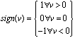 | (4) |
3.3. Viscous Friction Model
A viscous friction occurs in the cases where there is an oil between the contact surfaces which reduces friction coefficient f. | (5) |
The friction force is proportionately dependent on the velocity of the mass. The friction coefficient fV is function of the used oil.
3.4. Coulomb Plus Viscous Friction Model
From the model name is clear that this model consists of sum Coulomb and viscous friction. This kind of friction model is given by equation: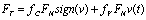 | (6) |
3.5. Stribeck Effect
For the most common situations the friction decreases with increasing velocity for a certain velocity regime. This is called the Stribeck effect. This kind of friction can be described as: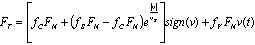 | (7) |
On the Figure 2 Stribeck friction is divided into three sections. | Figure 2. The Stribeck effect |
The first area represents static friction. The junctions deform elastically and there is no excursion until propulsive force does not reach the level of static friction force.The second area represents boundary lubrication. Within this area it is still solid to solid contact, the lubrication film is not yet built. The friction force decreases with increasing velocity but generally is assumed that friction in this area is higher than for fluid lubrication.The third area represents partial fluid lubrication. The lubricant is drawn into the contact area through motion or by sliding. The greater motion velocity is, the thicker the fluid film will be. The fourth area represents full fluid lubrication. Within this area the lubricant film is thick and contact bodies are completely separated to each other. On the Figure 3 the courses of individual friction models are shown.[5]Within this study the Static plus Coulomb friction model will be used for rectilinear motion modeling. It should be note that these friction models are only idealized models and real friction behaviour is a little bit different. 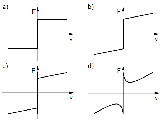 | Figure 3. The different kinds of friction models (a – Coulomb friction mode, b – Coulomb plus viscous friction model, c – Static plus Coulomb plus viscous friction model, d – Stribeck effect) |
4. Rectilinear Motion Modeling
In the second section the biological snake rectilinear motion was described. For mechanical modeling there are usually used masses, springs and dampers. In this study only the masses will be used. If we want to analyze rectilinear motion of a snake we have to its biological body as the series of N identical consecutive elements where each element performs some activity. These elements we replaced with masses with the weight m. On the Figure 4 is the snake body from the view of biology and on the Figure 5 is the model of the snake from the view of mechanics.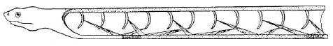 | Figure 4. The snake body |
 | Figure 5. The simplified model of a snake |
The mechanical system consists of N masses will behaves according to the following points:• One motion cycle consists of N phases• During one motion phase only one mass moves while other stay at rest• Each phase of a motion is divided into two sections. During the first section is i-th mass attracted to the (i+1)-th mass by propulsive force. During the second section is i-th mass decelerated. A velocity course of each phase behaves according to Figure 6.• During the first and second section of each phase the same total force affects i-th mass.• The actuators of the static masses affect so that they maintain their relative positions and these masses behave as one mass.• On the moving mass affects total external force which is the same in each phase• Each phase lasts the same time• Angle α changes from 0° up to αmax what is the maximum angle when the mass still stays at rest (does not slide down).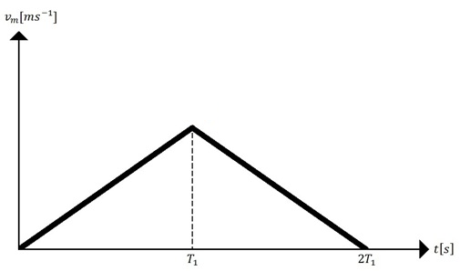 | Figure 6. The course of velocity during a one phase |
On the Figure 5 is simplified model of a snake on the flat surface without any inclination. In general, we derive mathematical model for inclined surface which can be use for model without any inclination as well. On the Figure 7 the free-body diagram of i-th moving mass is shown (i=2, 3, …, N-1). 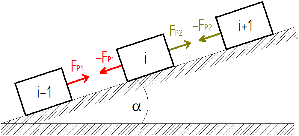 | Figure 7. The free body diagram of i-th moving mass on the flat inclined surface |
The sum of total external forces affecting i-th moving mass during the first section of phase can be expressed through the matrix: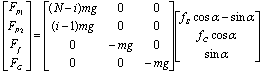 | (8) |
The sum of total external forces affecting i-th moving mass during the second section of phase can be expressed through the matrix: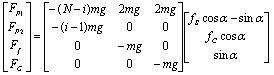 | (9) |
Where FP1, FP2, Ff and FG are first and second propulsive force, friction force and gravitational force, respectively. m is weight of i-th mass and g is acceleration of gravity.The force affecting the 1-th or N-th mass equals:From the basic Newton´s mechanics it can be derived the phase duration. The each phase will be last the time: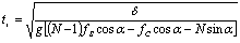 | (11) |
Where δ is a maximal possible distance between two masses. Subsequently we can write the average velocity equation for N-mass moving system: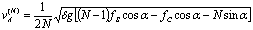 | (12) |
From the equation (12) we can derive optimal number of masses N for the maximum velocity of this mechanical system. The basic equation for determine optimal number N is: | (13) |
The equation (13) serves us to find the local extreme of the function of average velocity. After computing equation (13) we obtain following formula for optimal number of masses N for the maximal velocity: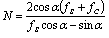 | (14) |
As can be seen the optimal number of masses N for the maximal velocity is dependent only on friction coefficients and angle of inclination.On the Figure 8 we can see average velocity dependence on the number of masses N with different angles of surface inclination. The simulations were done in software Matlab with following coefficients: fs = 0.5, fc = 0.3, δ = 0.02 m, g = 9.81 ms-2.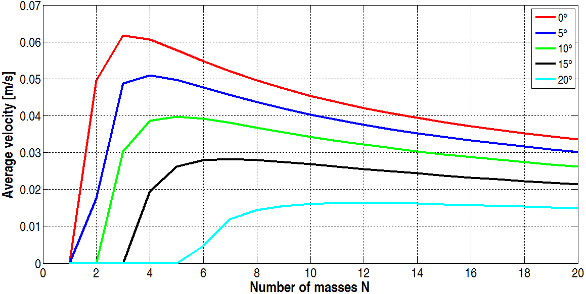 | Figure 8. The average velocity dependence courses on number of masses N with different angles of surface inclination |
As we can see the maximum average velocity the mechanical system reaches with three masses on the flat surface with inclination 0°.
5. Conclusions
The paper deals with the snake rectilinear motion modeling on the flat inclined surface. In the paper the mathematical model is established by means of Coulomb friction model. The propulsive forces FP1 and FP2 for i-th moving mass are determined. From the Newton´s mechanics the average velocity equation is derived. As can be seen the average velocity is not dependents on mass weight m (in the case where each mass is the same) but especially on number of used masses N. The optimal number of masses N is derived from the average velocity equation and the average velocity dependence on number of masses N with different angles of surface inclination is shown. The N-mass system will have the maximal velocity when angle of inclination is 0° and N=3.
ACKNOWLEDGEMENTS
The author would like to thank Slovak Grant Agency – project VEGA 1/0454/06 “Research on mechatronic systems imitating snake locomotion in confined and variable area”.This contribution is also the result of the project implementation: Centre for research of control of technical, environmental and human risks for permanent development of production and products in mechanical engineering (ITMS:26220120060) supported by the Research & Development Operational Programme funded by the ERDF.
References
| [1] | J.K. Hopkins, B. W. Spranklin, and S. K. Gupta, A survey of snake-inspired robot designs, Bioninspiration and Biomimetics, 2009. |
| [2] | A. Maity, S. K. Mandal, S. MAzumder, and S. Gosh, Serpentine robot: An overview of current status & prospect, 14th national conference on machines and mechanisms, pp. 275, December 2009. |
| [3] | S. Dalilsafaei, Dynamic analyze of snake robot, World academy of science, engineering and technology 29, 2007. |
| [4] | H. Olsson, K. J. Åström, C. Canudas de Wit, M. Gäfvert, and P. Lischinsky, Friction models and friction compensation, European journal of control, No. 4, pp. 176-195, December 1998. |
| [5] | B. Amstrong, Stick slip and control in low-speed motion, IEEE transaction on automatic control, vol. 38, No. 10, 1993. |
 Abstract
 Reference
 Full-Text PDF
 Full-Text HTML