International Journal of Mechanics and Applications

p-ISSN: 2165-9281    e-ISSN: 2165-9303

2012;  2(3): 24-28

doi: 10.5923/j.mechanics.20120203.01

Influence of Pin Profile on Quality of Friction Stir Lap Welds in Carbon Fiber Reinforced Polypropylene Composite

H. Ahmadi 1, N.B.Mostafa Arab 1, F.Ashenai Ghasemi 1, R.Eslami Farsani 2

1Faculty of Mechanical Engineering, Shahid Rajaee Teacher Training University, Tehran, Iran

2Faculty of Mechanical Engineering, K. N. Toosi University of Technology, Tehran, Iran

Correspondence to: H. Ahmadi , Faculty of Mechanical Engineering, Shahid Rajaee Teacher Training University, Tehran, Iran.

Email:

Copyright © 2012 Scientific & Academic Publishing. All Rights Reserved.

Abstract

In recent years, interest on friction stir welding has grown more since such a joining technique allows welding of light weight alloys like aluminum and its alloys which are difficult to weld or even unweldable with the traditional fusion welding processes. This process can also be one of the joining processes considered for welding polymer matrix composites such as polypropylene composites which find a number of applications in different industries. This paper presents the effect of tool pin profile on surface appearance and tensile shear strength of friction stir lap welds in carbon fiber reinforced polypropylene composites with 4 mm thickness. Four high speed steel tools with different pinprofiles of threaded cylindrical, threaded cylindrical-conical, simple cylindrical-conical and threaded conical were employed for this study. Using these tools, lap welds were made under similar conditions of tool rotational speed, welding speed and tilt angle. Specimens were prepared for tensile shear testing. The tensile shear test results showed that the threaded cylindrical-conical tool produced a weld with better surface appearance and higher tensile shear strength.

Keywords: Friction Stir Welding, Polypropylene Composite, Carbon Fiber, Tensile Shear Strength, Pin Profile

1. Introduction

Fiber reinforced thermoplastic composites have beenintroduced as structural materials for high performanceapplications because of their many advantages such as improved toughness, good mechanical properties, lowdensity, resistance to chemical reaction, recyclability, high temperature strength and infinite shelf life. The mostimportant advantage of thermoplastic composites may lie in their potential for rapid and low price production[1]. In recent years, usage of thermoplastic olefins such aspolypropylene (PP) has increased[2]. The surfaceproperties of thermoplastic composites are conspicuously improved with the addition of reinforcing fillers to the bulk of the material[3]. The common types of reinforcingmaterials for thermoplastic composites are carbon fibre (CF) and glass fibre (GF). In order to create large / complex structures made of thermoplastic composites several, simple components must be joined together. Friction stir welding (FSW) may be one of the options to joint the thermoplastic composites.
FSW patented in 1991 in the Welding Institute (TWI) of the United Kingdom is a type of solid state welding in which conversion of mechanical energy into thermal energy is used to join materials. In FSW, the joining takes place through the movement of a rotating shouldered tool with profiled pin plunged into the joint line between two pieces of sheet or plate material. When the rotating tool moves along the weld line, the material is heated up by friction produced between the shoulder of the tool and the surface of the work piece to be welded[4]. The strength of the material of the interface between the rotating tool and work piece falls below the applied shear stress as the temperature rises, so that plasticized material is extruded from the leading side to the trailing side of the tool. The tool is then steadily moved along the joint line giving a continuous weld[5]. Figure 1 schematically shows FSW process of lap joints.
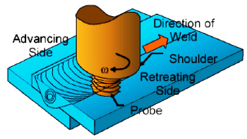
Figure 1. Schematic of the friction stir lap welding process [6]
Buffa et al.[7] reported that in FSW processof lap joints, tool profile had significant effect on mechanical properties. They used three tools with different pin profilesto weld aluminum alloy AA2198-T4 and came to the conclusion that cylindrical-conical tool in comparison to conical tool and cylindrical tool results in joints with better quality.
De filippis et al.[8] studied the effects of different shoulder geometries on the mechanical and microstructural properties of friction stir welded 6082 T2 aluminium alloy in the thickness of 1.5 mm. The three studied tools differed from shoulders with scroll and fillet, cavity and fillet, and only fillet. The results showed that, for thin sheets, the best joint has been produced by a shoulder with cavity and fillet.Kumar et al.[9] studied the effect of tool pin profile onmicrostructural development and mechanicalproperties of friction stir welded precipitation hardenable Al-Zn-Mg alloy in the thickness of 4.4 mm and concluded that joints welded with frustum-shaped rounded-end pin profile had better mechanical properties compared to cylindrical flat-end pin profile. Watanabe et al.[10] studied the weldability of FSW AZ31 magnesium alloy/ SS400 steel, and reported that the rotation speed and the position of the pin axis had asignificant effect on the strength and the microstructure of the joint. Cao and Jahazi[11] studied the effect of welding speed on microstructures and mechanical properties offriction stir welded AZ31B-H24 magnesium alloy andconcluded that as the welding speed increased, the grain size in the stir zone decreased while the yield strength increased. Higher welding speeds produced slightly higher hardness in the stir zone and the tensile strength increased first with increasing welding speed but remained constant later. Kumar et al.[12] have studied the mechanism of FSW and the role of the tool in formation of welds in aluminum alloy 7020-T6. They used a tool with frustum pin of H13 whose hardness was about 55HRC. They conducted the experiments using a vertical milling machine while keeping constant welding parameters such as rotational speed (1400 rpm), welding speed (80 mm/min) and tilt angle (2°). They concluded that as the contact surface of the tool increases, the amount of the weld defect decreases. They also indicated that in the first phase of welding, the tool shoulder does not touch the welding material fully and as a result the axial force will not beenough to create heat, therefore, a defective joint results. The main reason for weld defect at the first phase is thelack of contact surface between the shoulder and the materials. When the contact surface between the shoulder and thematerials increases, the axial force increases as well. When the axial force exceeds a certain limit, material transportation from the leading edge will be restricted to the weld cavity, therefore, appropriate heat and hydrostatic force will be created which leads to defect free welding. Buffa et al.[13] reported that in FSW process, a defect free weld will result only through creating appropriate heat and friction.
Arab et al.[14] investigated the effects of FSW process parameters (tool pin geometry, tool rotational speed, work linear speed and tool tilt angle ) on weld appearance and tensile strength of butt joints in PP composites with 30% GF and concluded that the tool pin geometry had a significant influence on weld appearance and the effects of rotational speed and tilt angle on weld appearance and tensile strength were more than that of work linear speed.
Although research on butt welding of PP composites has been carried out[14], but lap welding of this composite applying FSW method has not been reported yet. This study can be the first work on this issue. In the present study, it is tried to examine the effect of welding parameters on surface appearance and tensile shear strength of lap joints of PP composites with 20% CF as influenced by the tool pin profilewhile keeping rotational speed, welding speed and tilt angle fixed.

2. Experimental Details

2.1. Materials

Plates of PP composite with 20% CF were used as the parent material in this investigation. The plates to be lap welded were of 101mm×50mm×4mm size. A verticalmilling machine was employed to provide rotational speed, welding speed and tilt angle. Four tools of high speed steel (HSS) were used for lap welding of the pieces. A clamping fixture as shown in Figure 2 was used in order to fix the specimens to be welded on the milling machine, so that they would not separate during welding process.
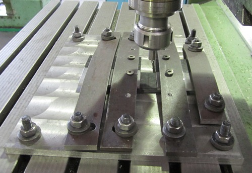
Figure 2. Clamping fixture used in experiment
Geometric features of the four tools are shown in Table 1. These tools were used with a fixed rotational speed of 1000 rpm, welding speed of 16 mm/min, and tilt angleof 1°after conducting a number of trial runs to select the above values for these parameters. Figure 3 alsoshows the FSW tools in the present study.
Table 1. Different pin profiles of four friction stir tools
     
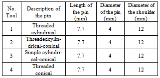
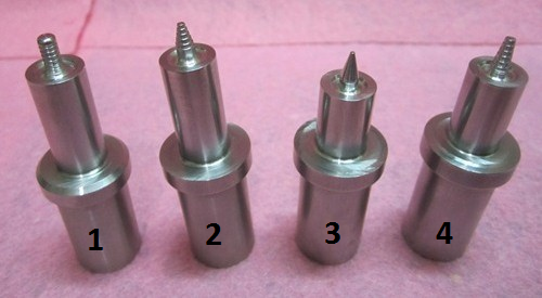
Figure 3. FSW tools with different pins and shoulders

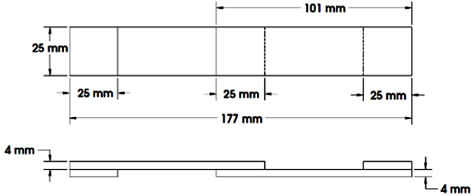
2.2. Tensile Shear Strength Test Specimen Preparation

The tensile shear strength test specimens whosedimensions are given in Figure 4 were prepared according to ASTM D5868[15] from the middle of the welded plates to eliminate the start and end effects of the welding process.
Figure 4. Tensile shear strength test specimen [15]
Tensile shear strength tests were conducted using aSANTAM Universal Testing Machine-STM-150, keeping the cross-head speed at 2 mm/min during the loadingconditions. Figure 5 shows a specimen during the test.
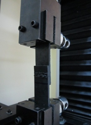
Figure 5. specimen during tensile shear strength testing

3. Results and Discussion

3.1. Effect of Tool Pin Profile on Surface Appearance

The shoulder diameter, the pin length and diameter are geometric features of the tool which affect the amount of heat generated and material flow during welding[16-18]. After contacting the work piece, the shoulder creates friction and causes heat generation which consequentlyresults in weld width. The more the heat created by the shoulder, the material flow will occur more and easier, however, this heat should not exceed a certain limit because in that case; partial melting occurs and the material sticking to the tool surface results in low weld quality. If the length of the pin is short for the thickness of the two plates, the second piece which is under the first one will not be welded well, therefore, lack of penetration defect will occur. Although the shoulder has the main role of creating heat, the pin to a lesser degree also plays a role in creating heat[16-18]. Therefore, shortness of the pin because of decrease in contact surface with the lower piece results in decrease of the created heat in the lower piece. Compensating the shortness of the pin through pushing the tool more in the work piece causes pressure increase which forces the materials out of themolten pool, therefore, flash defect forms. Figure 6 shows such a defect. As a result, the pin length should be chosen accurately. To do so, it is better to choose the pin length 0.2 mm to 0.3 mm shorter than the sum of the thickness of the two pieces[19].
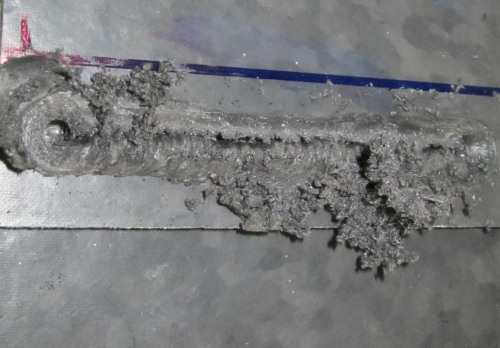
Figure 6. Formation of flash defect while welding
The surface appearance of welds produced by the four different tools is shown in Figure 7. As seen in Figure 7, the resulted weld surface appearance from tool number 2 (Figure 7-b) is better in comparison to the surface appearance produced by other welding tools. Tool number 2 results in better weld because its pin is threaded cylindrical-conical, therefore, its contact surface with the work piece is wider and greater friction will be created and as said creating more friction results in more heat [13]. On the other hand, the thread around the tool pin causes great amount of turbulence on the weld seam and molten material mixes better and as a result a better quality weld is produced. Tool number 3 creates the worst weld surface quality (Figure 7-c) because it is the only tool whose pin is simple and this does not cause the materials to mix well when the tool pin enters the molten material and creates lesser turbulence compared to other tools. When material turbulence in the weld pool drops, lesser heat and friction is created, which results in weld quality to drop. In addition, it can be observed that tools number 2 and 3 are alike except for their pins. The presence of thread on tool pin issignificantly important therefore tool number 2 is the best and tool number 3 is the worst one. Tool number 1 has a lesser contact surface with the work piece in comparison to tool number 2 and this contact surface decrease results in friction and heat drop and ultimately decreases weld surface quality (Figure 7-a). Tool number 4 whose pin is threaded conical, creates lesser contact surface with the work piece compared with tool number 1, which causes the quality of the weld surface (Figure 7-d) in tool 4 to decrease in comparison to that of tool 1 because lesser heat and friction are generated at the contact area.
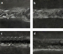
Figure 7. Effect of tool pin profile on weld surface appearance, a: tool 1, b: tool 2, c: tool 3, d: tool 4

3.2. Effect of Tool Pin Profile on Tensile Shear Strength

Figure 8 shows the results of tensile shear strength tests. According to these results, it can be observed that tensile shear strength of the weld from tool number 2 is higher than all other tools and is about 5.70 MPa. As said in the previous section, weld surface appearance achieved from tool number 2 is higher than all other tools and it can be another reason for higher tensile shear strength with tool number 2. The tensile shear strength from tool number 3 is lower than other tools and ( 3.84 MPa ) and this is because the materialturbulence on the weld pool using tool number 3 is lower compared to other tools and therefore lesser friction and heat As seen in Figure 7-c, porosity and voids created on the weld surface can be the reason for lowertensile shear strength with tool number 3.
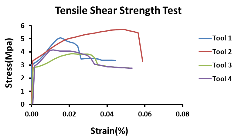
Figure 8. Results of tensile shear strength test
All the tensile shear strength test specimens fractured from the weld zone as shown in Figure 9 indicating this zone is the weakest part of the joint.
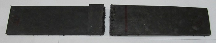
Figure 9. The tensile shear strength test fractured specimen

4. Conclusions

In the present study, four different tools for FSW of PP composites with 20% CF were used in order to investigate the effect of tool pin profile on weld appearance and tensile shear strength. Results showed that tool pin profile plays a significant role in creating friction, heat and material flow in FSW. By keeping constant parameters such as rotational speed, welding speed and tilt angle, it was observed that the tool pin profile has a significant effect on the surfaceappearance and weld strength.It was observed that tool number 2 produced a weld without any surface porosityand voids with better tensile shear strength in comparison to other tools. Therefore, tool number 2 is considered to beappropriate for friction stir lap welding of PP composites with 20% CF because it creates both better weld surface appearance and tensile shear strength.

References

[1]  Z.S. Colak, F.O. SonmezandV. Kalenderoglu, “Process Modeling andOptimization of Resistance Welding for Thermoplastic Composites,”Journal of Composite Materials, vol.36, pp.721, 2002.
[2]  S. Zokaei, M.R. Lesan Khosh, R. bagheri, “Study of Scratch Resistance in Homo- and Co- Polypropylene Filled withNanometric Calcium Carbonate,” Materials Science andEngineering A, vol.445- 446, pp.526 – 536, 2007.
[3]  J. Song, G.W. Ehresntein, “Advances in CompositeTribology,” Elsevier Science Publishers, pp.19, 1993.
[4]  S. Benavides, Y. Li, L.E. Murr, D. Brown, J.C. McClure,“Low Temperature Friction-Stir Welding of 2024 Aluminium,” Scripta Materialia, vol.41(8), pp.809–815, 1999.
[5]  K.V. Jata, S.L. Semiatin, “Continuous Dynamic Recrystallization During friction Stir Welding of High Strength AluminumAlloys,” Scripta Materialia, vol.43(8), pp.743–749, 2000.
[6]  D. Fersini, A. Pirondi, “Fatigue Behaviour of Al2024-T3 Friction Stir Welded Lap Joints,” Engineering Fracture Mechanics, vol.74, pp.468–480, 2007.
[7]  G. Buffa, G. Campanile, L. Fratini, A. Prisco, “Friction StirWelding of Lap Joints: Influence of Process Parameters on the Metallurgical and Mechanical Properties,” Materials Science and Engineering A, vol.519, pp.19-26, 2009.
[8]  A. Scialpi, L.A.C. De Filippis, P. Cavaliere, “Influence of Shoulder Geometry on Microstructure and MechanicalProperties of Friction Stir Welded 6082 Aluminium Alloy,” Materials and Design, vol.28, pp.1124-1129, 2007.
[9]  K. Kumar, Satish V. Kailas, T.S. Srivatsan, “Influence of Tool Geometry in Friction Stir Welding,” Materials and Manufacturing Processes, vol.23(2), pp.188 -194, 2008.
[10]  T. Watanabe, K. Kagiya, A. Yanagisawa, H. Tanabe, “Solid State Welding of Steel and Magnesium Alloy Using a Rotating Pin-Solid State Welding of Dissimilar Metals Using a Rotating Pin,” Quarterly Journalof the Japan Welding Society, vol.24, pp.108-15, 2006.
[11]  X. Cao, M. Jahazi, “Effect of Welding Speed on the Quality of Friction Stir Welded Butt Joints of a Magnesium Alloy,”Materials and Design,vol.30, pp.2033-2042, 2009.
[12]  K. Kumar, Satish V. Kailas, “The Role of Friction StirWelding Tool on Material Flow and Weld Formation,” MaterialsScience and Engineering A, vol.485, pp.367-374, 2008.
[13]  G. Buffa, J. Hua, R. Shivpuri, L. Fratini., “Design of the Friction Stir Welding Tool Using the Continuum Based FEM Model,” Material Science and Engineering A, vol.419, pp.381-388, 2006.
[14]  G.H. Payeganeh, N.B. Mostafa Arab, Y. Dadgar Asl, F.A. Ghasemi and M. Saeidi Boroujeni, “Effects of Friction Stir Welding Process Parameters on Appearance and Strength of Polypropylene Composite Welds,” International Journal of the Physical Science, vol.6(19), pp.4595-4601, 2011.
[15]  ASTM Standard D 5868., “Standard Test Method for Lap Shear Adhesion for Fiber Reinforced Plastic(FRP) ,” In: Annual book of ASTM standard, 2002.
[16]  Yuh J. Chao, X. Qi, W. Tang, “Heat Transfer in Friction Stir Welding-Experimental and Numerical Studies,”Transactions of the ASME, vol.125, pp.138-145,February 2003.
[17]  M. Song, R. Kovacevic, “Thermal Modeling of Friction Stir Welding in a Moving Coordinate System and Its Validation,”International Journal of Machine Tools & Manufacture, vol.43, pp. 605-615, 2003.
[18]  P. Colegrove, “Three Dimensional Flow and ThermalModeling of the Friction Stir Welding Process,”Proceedings of the second International Symposium on Friction Stir Welding, Sweden, August 2000.
[19]  K. Elangovan, V. Balasubramanian, “Influences of Tool Pin Profile and Tool Shoulder Diameter on the Formation of Friction Stir Processing Zone in AA6061 Aluminium Alloy,” Materials and Design, vol.29, pp.362-373, 2008.