-
Paper Information
- Previous Paper
- Paper Submission
-
Journal Information
- About This Journal
- Editorial Board
- Current Issue
- Archive
- Author Guidelines
- Contact Us
International Journal of Mechanics and Applications
p-ISSN: 2165-9281 e-ISSN: 2165-9303
2012; 2(1): 20-24
doi:10.5923/j.mechanics.20120201.04
Comparing Plastic Deformations Produced by HPT and ECAP Processes Using the Finite Element Analysis Method
Zeynali E., Bisadi H.
Mechanical Engineering Department, Iran University of Science & Technology, Tehran, Iran
Correspondence to: Zeynali E., Mechanical Engineering Department, Iran University of Science & Technology, Tehran, Iran.
| Email: |  |
Copyright © 2012 Scientific & Academic Publishing. All Rights Reserved.
Applying Sever Plastic Deformation (SPD) to metals in order to form a nanocrystalline structure in them has been the subject of many recent researches. Investigations show that the nanocrystalline structure improves mechanical properties such as the yield strength and wear resistance. Among the SPD methods, more attention has been paid to the High Pressure Torsion (HPT) and Equal Cannel Angular Pressing (ECAP) methods. Irrespective of different work-piece geometries produced through these methods, studying the amount of plastic deformation as well as the method of applying it could be useful in comparing these processes and choosing the more effective ones. In this article, the results of finite element analysis of the HPT and ECAP processes on pure commercial aluminum are provided and the rate of success of each process in applying the SPD to the part is studied. Plastic deformation is considered as a parameter for calculating the amount of grain refinement. The two methods are compared and their advantages and disadvantages are discussed in the end.
Keywords: HPT, ECAP, nanocrystal, finite element, plastic deformation
Cite this paper: Zeynali E., Bisadi H., Comparing Plastic Deformations Produced by HPT and ECAP Processes Using the Finite Element Analysis Method, International Journal of Mechanics and Applications, Vol. 2 No. 1, 2012, pp. 20-24. doi: 10.5923/j.mechanics.20120201.04.
Article Outline
1. Introduction
- The grain size in polycrystalline materials plays a very important role in their mechanical strength and wear resistance. In general, a fine-grained material structure has many advantages over a coarse-grained one, and besides improving the mechanical properties, it helps raise the possibility of applying superplastic deep drawing processes to that material [1-6]. Such structures in polycrystalline materials are known as Ultra Fine Grained (UFG)[7,8]. UFG materials are divided into microcrystal and nanocrystal groups, and in the latter group, the size of the grains is reduced to 200nm. The two main methods for making UFGs are the bottom-up and the top-down methods[9]. In the bottom-up method, the bulk is made through the merging of atoms or solid nanometric particles. Like the inert gas condensation[10] and electro deposition[11] methods. These methods too, have the ability to produce materials with desired grain refinements; however, they have their own disadvantages and flaws as well. One flaw is the high risk of pollution infiltration, while the other is the inevitability of residual porosity. But in the top-down methods, there are no problems of pollution and porosity. In these methods, the initially coarse-grained work-pieces go through the relevant process and the desired grain refinement is achieved. There are several methods in this category, and all of them are based on imposing high deformation upon the material. The top-down methods are generally known as severe plastic deformation (SPD) processes[12].
2. The SPD Processes
- The SPD is a process in which the formation of the desired metal is achieved through applying high hydrostatic pressure. The initial metal part is subjected to high deformation, and the desired grain refinement is achieved, without changing the overall dimensions of the initial workpiece. Among the SPD methods, more attention has been paid to the HPT and ECAP processes[13-15].
2.1. The ECAP Process
- So far, many useful investigations have been conducted by researchers on the ECAP process. In Fig. 1, the principles of the ECAP process are shown[13]. In this figure, the conduit angle
 and the bend angle
  are shown. Both of these angles play an important role in the process. The workpiece in this case is a rod or a wire which is placed in the conduit and then is forced into the die with the help of a punch press. The workpiece deforms by means of simple shear strain that accumulates and builds up when the workpiece passes the edges of the die. In practice, for simplifying the process, the angle of conduit is set at 90 degrees. The bend angle has a lesser effect on the amount of applied deformation, and in detachable dies it could be disregarded; however, in fixed and non-detachable dies, some bend angle is inevitable. Although, severe plastic deformation is applied while the workpiece passes through the shear plane, the sample leaves the die without any changes on its cross sectional area. Therefore, it could be placed within the die again and go through another pass of the process. In practice, repetition of several passes is common in order to increase the applied plastic deformation. Therefore, in each pass, relative to the previous one, the samples are rotated 90 to 180 degrees around the axis normal to the cross sectioned area [13].
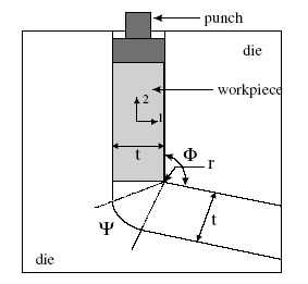 | Figure 1. The schematic principles of the ECAP process[13] |
2.2. The HPT Process
- In this method, while the workpiece is under a high axial pressure, it is subjected to a moment as well; so, a severe shear strain is applied to the material. This deformation would finally lead to a grain refinement of nanometric scale. Fig. 2 shows a schematic view of this process[16].
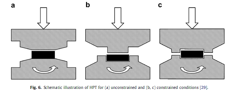 | Figure 2. schematic principle of the HPT process [16] |
 | (1) |
 is the friction stress, ky is the constant of yielding, and d is the grain size.According to this relation, it becomes clear that the yield stresses of the materials resulting from the HPT are high, because the grains are refined at nanometric levels as a result of this process. In the HPT process, hydrostatic pressure is increased up to 5GPa and even to 7GPa in some reports. Due to such high pressures, the workpieces producible in the HPT method are relatively small, and also owing to the nature of the process, they have an axisymmetrical geometry. The HPT process is used more for producing discs with a diameter of about 10mm and a thickness of 1mm, and rings with an equal surface area. In Fig. 3, the geometry of the workpiece is shown, depicting the deformation applying angle and the parameters that are used for calculating the deformation[19].
 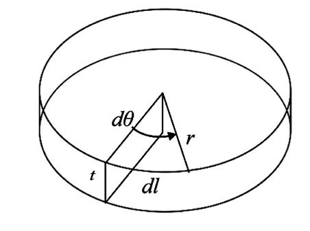 | Figure 3. Deformation applying angle and the parameters for calculating the deformation[19] |
 | (2) |
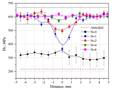 | Figure 4. the results of hardness measurement for a disc along the radial positions[22] |
3. Finite Element Simulation
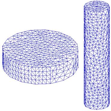
- When it comes to the geometry and dimensions of workpieces, the ECAP process is more versatile and accommodating than the HPT process. In this article, a cylinder with a diameter of 20mm and a length of 10cm was used as an ECAP workpiece, and a disc with a diameter of 20mm and a thickness of 5mm was used to simulate the HPT process. The finite element analysis was performed using the commercially available software “DEFORM 3D” and triangular elements were used to simulate both processes. Both workpieces were made of pure commercial aluminum. The meshed workpieces are shown in Fig. 5.
 | Figure 5. Meshed workpieces for the simulation of ECAP and HPT processes |
3.1. The ECAP Process Simulation
- In order to simulate the ECAP process, a die with a conduit angle of 90 degrees and a bend angle of 0 degree was used. The punch's movement speed within the conduit was
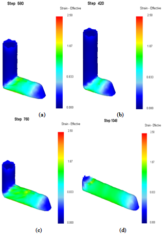
 . The workpiece went through one ECAP pass and the simulation process was stopped once the entire workpiece had passed by the conduit angle. The simulation results of the ECAP process are shown in Fig. 6. Changes in the amount of effective strain in the workpiece, throughout the ECAP process, are shown in Figs. 6(a) to 6(d). In Fig. 6(a) only a small portion of the workpiece has passed the conduit angle, and in Fig. 6(d), the entire workpiece has experienced one ECAP pass. As shown in this figure, plastic deformation is applied as the workpiece passes by the conduit angle. After passing through this area, deformation remains almost contant at every point of the workpiece. Although, as a result of friction with the conduit wall, a small amount of strain may be produced on the workpiece surface as it moves through the conduit, but this strain could be disregarded. According to the simulation results, the amount of strain produced from one ECAP pass is about 1.5, and in order to increase the effective strain, the workpiece must be placed within the conduit again and the process must be repeated.
 | Figure 6. Simulation results of the ECAP process |
3.2. The HPT Process Simulation
- The HPT process simulation is carried out on a semi- constrained workpiece. Fig.7 shows the deformation of the workpiece during the process as well as the amount of effective strain at every point of the workpiece.
 | Figure 7. Deformation of the workpiece during the HPT process |
4. Discussion and Conclusions
- According to the results of the finite element simulations, the HPT and ECAP processes could be compared to one another from three aspects:1) The amount of plastic deformationBecause of the high pressure applied in the HPT process, and the continuous circular deformation, the amount of plastic deformation caused by the HPT process is more than the ECAP process. Therefore, it could be concluded that more grain refinement is obtained in metals through the HPT process.2) The ease of process operation In the ECAP process, we have to repeat the operation and the workpiece must experience multiple passes through the conduit in order to achieve a large amount of plastic deformation. While, the increase in the amount of deformation in the HPT process is simply obtained by increasing the number of rotations. Therefore, it is easier to increase the amount of deformation in the HPT process than it is in the ECAP process.3) Geometry and dimensions of the partsWhen it comes to geometrical forms and dimensions of the parts, a much larger cross sectional area can be accommodated by the ECAP process compared to the HPT process. In the ECAP method, the workpieces could be thin rods, cylindrical parts with a diameter of 20mm, or even workpieces with square sections. But, since in the HPT process, pressures of several GPa are applied on the surface of the workpiece, there are size limitations, and in order to achieve such pressures, the researchers usually use small workpieces. On the other hand, as a result of the axisymmetrical nature of the HPT process, the parts produced through this process have an axisymmetrical form which includes discs and rings.
 Abstract
 Reference
 Full-Text PDF
 Full-text HTML