D. Abdullah H. AlEssa
Department of Mechanical Engineering, Engineering Faculty, Northern Borders University, Arar, Kingdom of Saudi Arabia
Correspondence to: D. Abdullah H. AlEssa, Department of Mechanical Engineering, Engineering Faculty, Northern Borders University, Arar, Kingdom of Saudi Arabia.
| Email: |  |
Copyright © 2012 Scientific & Academic Publishing. All Rights Reserved.
Abstract
The enhancement of natural convection heat transfer from a rectangular fin provided with rectangular perforations is investigated. The perforated fin is compared with its equivalent solid one. The parameters considered are geometrical dimensions and thermal properties of the fin and that of the perforations. The study considered the gain in fin area and of heat transfer coefficients due to perforations. The results showed that, for certain values of rectangular perforation dimension, the perforations lead to an augmentation in heat dissipation of the perforated fin over that of the equivalent solid one. The magnitude of heat dissipation enhancement depends upon the fin thickness, its thermal conductivity, the perforation dimension, lateral and longitudinal spacings. Finally, the study showed that, the perforating of the fins enhances heat dissipation rates and at the same time decreases the weight of the fin.
Keywords:
Finite Element, Perforated Fin, Heat Dissipation, Heat Transfer Augmentation, Natural Convection
Cite this paper: D. Abdullah H. AlEssa, Augmentation of Heat Transfer of a Fin by Rectangular Perforations with Aspect Ratio of Three, International Journal of Mechanics and Applications, Vol. 2 No. 1, 2012, pp. 7-11. doi: 10.5923/j.mechanics.20120201.02.
1. Introduction
The study of improved heat transfer performance is referred to as augmentation or enhancement of heat transfer. The heat transfer augmentation is very important subject in industrial heat exchangers and other thermal application. There are many techniques which are available for augmentation for single or two-phase heat transfer in natural or forced convection. These techniques may be passive methods or active schemes[1]. The heat transfer improvement may in general be achieved by increasing the heat transfer coefficients, by increasing the heat transfer surface areas or by both[1,2]. In most cases, the area of heat transfer is increased by utilizing extended surfaces in the form of fins attached to walls and surfaces[2]. Fins as heat transfer enhancement devices have been quite common. As the extended surface technology continues to grow, new design ideas emerge including fins made of anisotropic composites, porous media, interrupted and perforated plates[1-5]. Due to the high demand for lightweight, compact, and economical fins, the optimization of fin size is of great importance. Therefore, fins must be designed to achieve maximum heat removal with minimum material expenditure taking into account the ease of the fin manufacturing. Large numbers of studies have been conducted on optimizing fin shapes. Other studies have introduced shape modifications by cutting some material from fins to make cavities, holes, slots, grooves, orchannels through the fin body to increase the heat transfer surface area and/or coefficient[3-7]. One popular heat transfer augmentation technique involves the use of rough surfaces of different configurations. The surface roughness aims at promoting surface turbulence that is intended mainly to increase the heat transfer coefficient rather than the surface area[1,2]. For the natural convection from the rough surfaces, it concluded that there is an increase in heat transfer coefficient up to 100%[1]. It was reported that non-flat and interrupted surfaces have free convection coefficients that are 50 to 100% more than those of flat surfaces[2]. Several other researchers reported a similar trend for interrupted (perforated) fins. The improvement in heat transfer coefficient is attributed to the restarting of the thermal boundary layer after each interruption[2]. Perforated plates and fins represent an example of surface interruption and are widely used in different heat exchanger, film cooling and solar collector applications[1-5]. This study aims mainly at examining the extent of heat transfer enhancement from a horizontal rectangular fin under natural convection as a result of introducing surface modifications (perforations) to the fin. The modifications in this work are longitudinal vertical rectangular perforations with aspect ratio of 3 (b by 3b) made through the fin thickness. The study investigates the influence of perforations on heat transfer rate or heat dissipation rate of the perforated fin. The modified fin as it is called perforated fin, is compared to the corresponding solid (non-perforated) fin in terms of heat transfer rate. The study eventually attempts to make the best use of the material and size of a given fin, which involves some sort of optimization (maximization).
2. Assumptions for Analysis
The classical treatment of fins, which assumes one- dimensional heat conduction as the Biot number is very small, that is, less than 0.01[8,9] is considered. The perforated fin with rectangular perforations considered in this study is shown in Fig. 1. From which it is obvious that the transverse Biot number in z direction can be calculated by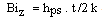 | (1) |
And the transverse Biot number in y direction () can be calculated by 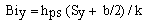 | (2) |
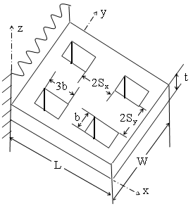 | Figure 1. The fin with (b by 3b) rectangular perforations |
As the values of (Biz) and (Biy) less than .01[8, 9] then the heat transfer in z and y directions can be assumed negligible and the one dimensional solution can be considered. If the values of (Biz) and (Biy) are greater than 0.01, the heat transfer solution must be in two or three dimensions. In this study the parameters of the perforated fin are restricted as they lead to values of (Biz) and (Biy) smaller than 0.01. According to the above discussion, the analysis and results reported are based on the following assumptions:1. Steady state one-dimension heat conduction.2. Homogeneous and isotropic fin material with constant thermal conductivity.3. No heat sources/sinks in the fin body.4. Uniform base and ambient temperatures.5. Uniform heat transfer coefficient over the whole fin solid surface (perforated or solid)6. Uniform heat transfer coefficient within the perforation
3. Heat Transfer Analysis
Based on the above assumptions, the energy equation of the fin along with the boundary conditions may be stated as below[10] | (3) |
The associated boundary conditions are1- At the fin base (x = 0):- | (4) |
2- At the perforated surfaces. 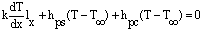 | (5) |
The fin with rectangular perforations as it is shown in Fig. 1 is solved numerically utilizing the finite-element technique as it is described by Abdullah H. M. AlEssa[11]. It is established that everything else being the same, heat dissipation from a fin, solid or perforated, depends on fin surface area and heat transfer coefficients. For the solid fin, both aspects are established. The average value of hsf in natural convection is given by[12]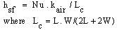 | (6) |
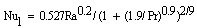
The average Nusselt number, Nu, is given by[12]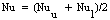 | (7) |
 | (8) |
 | (9) |
For the fin considered in this study, both perforated and non-perforated, the fin tip is a vertical surface for which the Nusselt number is given by[12]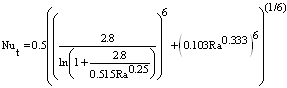 | (10) |
 | (11) |
For the perforated fin, three distinct heat transfer coefficients exist. The first one is the heat transfer coefficient of the solid portion of the perforated surfaces which can be calculated by the following expression[3]: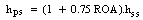 | (12) |
The second one is that the heat transfer coefficient within the perforation (hpc) where its Nusselt number (Nuc) is given by[12]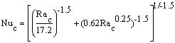 | (13) |
The third one is that the heat transfer coefficient at fin tip (ht) which its Nusselt number (Nut) is given by equation (10). The ratio of heat dissipation of the perforated fin to that of the solid one (RQF) is introduced and given by: | (14) |
The heat dissipation of the perforated fin (Qpf) is computed according to the finite element heat transfer solution described by Abdullah H. M. Al-Essa[11]. The heat dissipation of the solid fin (Qsf) is computed according to the exact solution described by Frank P. Incropera and David P. Dewitt[13]. The weight of the perforated fin is compared with that of the non-perforated one by using the weight ratio (RWF) which is given by: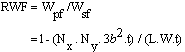 | (15) |
4. Results and Discussion
It is believed that comparing of the perforated fin with its solid counterpart is the best means to evaluate the improvements in heat transfer brought about by introducing the perforations. It is assumed that both fins have the same dimensions (the fin length is L= 50 mm and its width is W= 200 mm), same thermal conductivity, same base and ambient temperatures (100 and 20℃) respectively. The effect of introducing the perforations on the perforated fin performance is examined by comparing the perforated fin with its solid counterpart.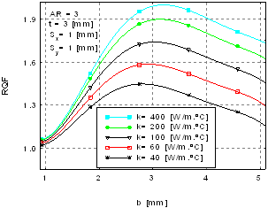 | Figure 2. Ratio of heat dissipation rate (RQF) vs. perforation dimension with variable fin thermal conductivity |
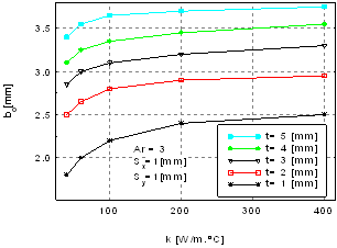 | Figure 3. Values of the optimum perforation dimension (b0) as a function of the fin thermal conductivity with variable fin thickness |
4.1. Ratio of Heat Dissipation Rate (RQF)
The ratio of heat dissipation rate from the perforated fin to that of the corresponding solid one RQF is studied in terms of perforation dimension b for different values of fin thickness. The results are shown in fig. 2. It shows that thicker fins produced larger heat transfer enhancement at any b. The variation of RQF with b at various t showed a consistent trend of increasing to a maximum followed by a decrease. This trend may be explained by the net effects of variation in fin heat transfer surface area and heat transfer coefficients due to perforations. Furthermore, the figure shows that RQF is a strong function of the perforation dimension b. The perforation dimension at which RQF ratio has its maximum value is referred to as the optimum perforation dimension b0. Fig. 2 indicates that the optimum dimension b0 is a function of the fin thickness and its thermal conductivity. The approximate values of b0 can be obtained from the graphs and their curves like that shown in figure 2. To obtain the approximate values of b0, fig. 2 was plotted for the fin thicknesses of (1, 2, 4 and 5 mm) and for thermal conductivities of (40, 60, 100, 200, 400 W/m.oC). The obtained values of b0 were plotted in figure 3 from which it is obvious that b0 is a strong function of the fin thickness while it slightly varies with its thermal conductivity.
4.2. Longitudinal Spacing (Sx)
To investigate the effect of longitudinal spacing Sx on the perforated fin performance, the heat dissipation ratio RQF was plotted as a function of the spacing Sx as shown in Fig. 4. This figure indicates that at any t, the RQF decreases with increase in Sx. This behavior is due to the fact that the increase in Sx means smaller number of perforations. This means loss of the element that causes heat transfer enhancement. So according to Sx spacing it is preferable to minimize it as possible.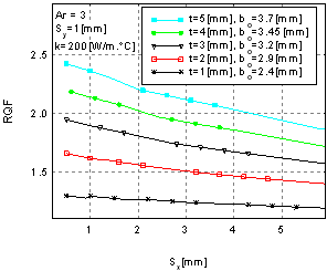 | Figure 4. Ratio of heat dissipation rate (RQF) vs. longitudinal spacing with variable fin thickness |
4.3. Lateral Spacing Sy
The effect of lateral spacing Sy on the perforated fin performance can be investigated by plotted RQF as a function of Sy for various values of the fin thickness and its thermal conductivity as shown in Fig. 5. The figure shows that RQF increases for low values of Sy and then tends to decline thereafter. It may be suggested here that the conflicting effects of fin thermal resistance and surface area are responsible for this trend. 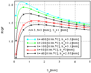 | Figure 5. Ratio of heat dissipation rate vs. lateral spacing with variable fin thermal conductivity |
Fig. 5 shows that RQF heavily depends on Sy. The figure also indicates that RQF values which is closely related to the optimum perforation dimension b0 are strong relation of the spacing Sy. In this region, the ratio RQF attains maximum value and then decreases as Sy increases. This means that there is an optimum associated value of Sy which is abbreviated as Sy0. Sy0 values strongly depend on the fin thickness and its thermal conductivity. The approximate values of Sy0 can be obtained graphically as shown in Fig. 5. The approximate values of Sy0 are plotted in Fig. 6. This figure shows that Sy0 decreases as fin thermal conductivity and its thickness increase.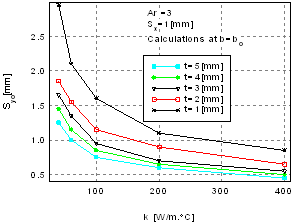 | Figure 6. Optimum lateral spacing vs. thermal conductivity with variable fin thickness |
To summarize the advantages of using the perforated fin at the optimum values of perforation geometry, the ratios of heat dissipation RQF and of weight RWF as functions of the fin thickness with variable fin thermal conductivity at the optimum perforation dimension b0 and optimum lateral spacing Sy0 are plotted in figures 6, 7 and 8. These figures show that the use of perforations in fins leads to enhance heat dissipation and decrease the fin weight. The enhancement increases and the weight decreases as the fin thickness and its thermal conductivity increases. This means that the use of perforated fin leads to enhance heat dissipation rates and at the same time leads to decrease in expenditure of fin material.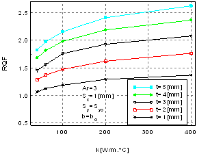 | Figure 7. Ratio of heat dissipation rate (RQF) vs. thermal conductivity at (b0 and Sy0) |
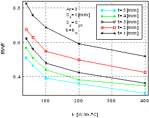 | Figure 8. Weight ratio (RWF) vs. thermal conductivity at (b0 and Sy0) |
5. Conclusions
1. For certain values of rectangular perforation dimension, the perforated fin enhances heat transfer. The magnitude of enhancement is proportional to the fin thickness and its thermal conductivity.2. The extent of heat dissipation rate enhancement for perforated fins is a complicated function of the fin dimensions, the perforation geometry and the fin thermophysical properties.3. The gain in heat dissipation rate for the perforated fin is a strong function of both the perforation dimension and lateral spacing. This function attains a maximum value at a given perforation dimension and spacing called the optimum perforation dimension ( ), and the optimum spacing (
 ) respectively.4. The perforation of fins enhances heat dissipation rates and at the same time decreases the weight of the fin.Nomenclature
References
| [1] | S.Kakac, A. E. Bergles, F. Mayinger , “ Heat Exchangers, Thermal- Hydraulic Fundamentals and Design” , Hemisphere Publishing Corporation, 1981. |
| [2] | A. E. Bergles, Technique to augment heat transfer. In Handbook of heat transfer Applications, (Edited by Werren M. Rohsenow, James P. Hartnett, and Ejup N. Ganic), Ch. 3, Second Edition, McGraw-Hill Book company, NY. |
| [3] | Al-Essa, A.H., Al-Hussien, F. M.S., “The effect of orientation of square perforations on the heat transfer enhancement from a fin subjected to natural convection", Heat and mass transfer 40 (2004) 509-515. |
| [4] | R. Mullisen and R. Loehrke, A study of flow mechanisms responsible for heat transfer enhancement in interrupted-plate heat exchangers, Journal of Heat Transfer (Transactions of the ASME) 108, 377-385 (1986). |
| [5] | C. F. Kutscher, Heat exchange effectiveness and pressure drop for air flow through perforated plates with and without crosswind, Journal of Heat transfer 116, 391-399, (May 1994). |
| [6] | AlEssa, A.H., 2000, “Enhancement of thermal performance of fins subjected to natural convection through body perforation”, Ph.D. thesis, Department of Mechanical Engineering, University of Baghdad, Iraq and University of Science and Technology. Jordan. |
| [7] | B. V. S. S. S. Prasad, A. V. S. S. K. S. Gupta, “ Note on the performance of an optimal straight rectangular fin with a semicircular cut at the tip”, Heat transfer engineering Vol. 14 , No. 1 1998. |
| [8] | P. Razelos and E. Georgiou , “Two–Dimensional effects and design criteria for convective extended surfaces”, heat transfer engineering Vol.13, No.3, 1992, p 38-48 |
| [9] | A. Aziz and V. Lunadini, Multidimensional steady conduction in convicting, radiating, and convicting-radiating fins and fin assemblies, Heat Transfer Engineering 16(3), 32-64 (1995). |
| [10] | Rao, S. S., "The Finite Element Method in Engineering", Second Edition, Elmsford, NY: Pergamon, 1989. |
| [11] | Abdullah H. M. AlEssa, "One Dimensional Finite Element Solution of the Rectangular Fin with Rectangular Perforations", WSEAS TRANSACTIONS on HEAT AND MASS TRANSFER, Issue 10, Volume 1, October 2006, p 762-768. |
| [12] | G. D. Raithby, K. G. T. Holands, Natural convection, In Handbook of Heat Transfer Applications 2nd Edn, (Edited by W. Rohsenow, J. Hartnett and E. Ganic), Ch. 6. McGraw-Hill Book Company, New York (1984). |
| [13] | Frank P. Incropera and David P. Dewitt, Fundamentals of Heat and Mass Transfer (Forth Edition), p. 110, John Wiley and sons, New York (1996). |
 Abstract
 Reference
 Full-Text PDF
 Full-text HTML