Daryoush Safarzadeh 1, Shamsuddin Sulaiman 1, Faieza Abdul Aziz 1, Desa Bin Ahmad 1, Gholam Hossein Majzoobi 2
1Department of Mechanical and Manufacturing Engineering-Faculty of Engineering-University of Putra Malaysia, 43400, UPM, Serdang, Selangor Darul Ehsan, Malaysia
2Department of Mechanical Engineering, Faculty of Engineering, Bu Ali Sina University, Hamadan, Iran
Correspondence to: Daryoush Safarzadeh , Department of Mechanical and Manufacturing Engineering-Faculty of Engineering-University of Putra Malaysia, 43400, UPM, Serdang, Selangor Darul Ehsan, Malaysia.
| Email: |  |
Copyright © 2012 Scientific & Academic Publishing. All Rights Reserved.
Abstract
One of the factors which affects on the sway of payload is crane hook. For determination the relationship between payload sway and hook peculiarities including mass and length, an approach was proposed based on the Lagrange equation to obtain equations of motion for a system with seven-degrees-of-freedom. A laboratory test by use of a special hook with adjustable mass and length was carried out to validate the results. Both theoretical and experimental outcomes confirmed the effect of hook on payload sway. Increasing the mass and length of hook will cause the pendulum motion of the payload to be suppressed in a short time.
Keywords:
Equation of Motion, Hook, Payload, Pendulum Motion, Sway Angle
Cite this paper:
Daryoush Safarzadeh , Shamsuddin Sulaiman , Faieza Abdul Aziz , Desa Bin Ahmad , Gholam Hossein Majzoobi , "An Approach to Determine Effect of Crane Hook on Payload Sway", International Journal of Mechanics and Applications, Vol. 1 No. 1, 2011, pp. 30-38. doi: 10.5923/j.mechanics.20110101.04.
1. Introduction
Among various types of cranes, hydraulic cranes are most important types used for transporting the loads from one place to another as well as loading and unloading the payload. One of the most important issues in cranes is swinging of payload produced by various factors deriving mostly from crane maneuvers and motions of crane components for performing the desired operations. Uncontrolled swaying motion slows down the movement and transmission of the payload process because extra time is required to let the swaying motion come to a stop. Uncontrolled swaying is also a safety issue that can result in serious injury. The natural sway of crane payload causes safety hazards, time delay and difficulty in positioning payload[4].To eliminate the adverse effects of most vibrations, one of the approaches is to make a complete study of the equation of motion of the system in question. The equation of motion expresses displacement as a function of time or will give the distance between any instantaneous position of the mass during its motion and the equilibrium position[12]. The sway of the payload is the most important contributor to dynamic loads, once these dynamic forces are known; however, it is then possible to predict a load spectrum that is the basis for modern fatigue and reliability design[2,1]. There are only a few researches regarding crane hook and already no research in the field of impression of hook peculiarities on pendulum motion in payload. Nevertheless, numerous approaches dealing with the sway-free transportation of crane loads and sway suppression control systems, for instance[4-7] and motion analysis of payload[10,11] have been proposed. However, up to now, the focus has been mainly on gantry and overhead cranes. For rotary or boom cranes, the anti-sway and trajectory tracking problem is treated only in theory[7] .There are contributions which focus on the modeling, simulation and analysis of rotary or boom cranes. For example, Kiss et al. (1999) investigated the flatness property for a class of cranes. They used Lagrange multipliers associated with geometric constraints between generalized coordinates in order to obtain dynamical models and to show differential flatness. Jerman et al. (2004) studied the dynamics of slewing crane and formulated a non linear mathematical model of the load sway during the slewing motion with consideration of damping, the friction in the main bearing and the air resistance. Wei et al. (1993) presented a mathematical model of the load sway on tower cranes. None of these researchers, however, considered the condition of simultaneous motion of crane and booms. They mainly studied the linear crane. In this paper, effect of mass and length of hook on pendulum motion of the payload in automotive hydraulic cranes is studied. Thus, a mathematical model of the load sway is proposed for a typical hydraulic crane. This model takes into account the entire crane motions together, including straight movement, steering and rotation of booms, which have not been considered in previous publications. Based on this model, the equations of motion for the system are determined.
2. Mathematical Model
2.1. Assumptions
For mathematical description, co-ordinate system xyz is introduced based on the following assumptions: 2.1.1. The entire crane and its components motions are considered simultaneously in determining the equations of motion. 2.1.2. The mathematical model is identical for most of the hydraulic cranes with two booms. However, in this study, an automotive hydraulic floor crane with two booms and two hydraulic cylinders is considered because of the best correspondence with the mathematical model (Figure 1). In this model, the effect of all crane motions including rotation of booms, steering and straight movement on the sway of payload is studied.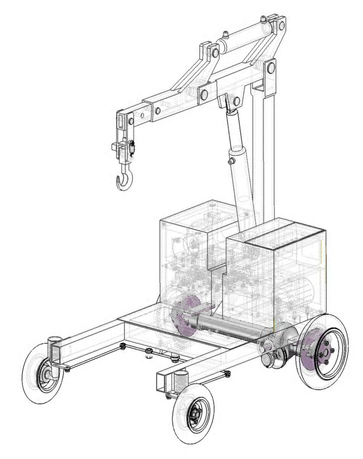 | Figure 1. Computer model of a typical automotive hydraulic floor crane. |
2.1.3. The entire motions of the components (except for steering), including the rotation of booms, hook and payload are considered as a general plane motion because of the crane movement. Therefore, the mass moment of inertia of the rotating parts is represented by [I] in the equations. Steering is assumed as a fixed-axis rotation. 2.1.4. Lp which represents the length of the element connecting the payload to the hook is considered weightless.2.1.5. Link Lp has displacement in x, y and z directions, but links Lh, LBm and LBa have displacement in x and z directions.2.1.6. Air resistance and wind effect on the crane and its components are not considered. Small and large angles of load sway are studied.
3. Equations of Motion
For determination of the equations of motion, the Lagrange's equation is used which a scalar procedure is starting from the scalar quantities of kinetic energy, potential energy and work expressed in the terms of generalized coordinates[7].It is presented here as: | (1) |
Where: is Generalized Coordinates, T is Kinetic Energy, U is Potential energy,
  is Non Potential Forces and
  is Generalized velocity. The mathematical model and assumptions give a seven DOF crane model and the generalized coordinate vectors can be chosen as follows: For determination of the equations of motion by using Lagrange's equation, the first step is to find the displacement and velocity of all masses.
3.1. Equations of Displacement, Velocity and Kinetic Energy of the Payload
 | Figure 2. Mathematical model for an automotive hydraulic floor crane. |
The equations of a payload which is hanging to the hook and has a 3D pendulum motion (Figure 2) can be expressed as follows:  | (2) |
 | (4) |
 | (5) |
 | (6) |
 | (7) |
 | (8) |
 | (9) |
 | (10) |
3.2. Equations of displacement, Velocity and Kinetic Energy of the Hook
Hook has only 2D motion in x and z directions. Therefore,  | (11) |
 | (12) |
 | (13) |
 | (14) |
 | (15) |
 | (16) |
 | (17) |
 | (18) |
 | (19) |
3.3. Equations of Displacement, Velocity and Kinetic Energy of the Auxiliary Boom
 | (20) |
 | (21) |
 | (22) |
 | (23) |
 | (24) |
 | (25) |
 | (26) |
3.4. Equations of Displacement, Velocity and Kinetic Energy of the Main Boom
 | (27) |
 | (28) |
 | (29) |
 | (30) |
3.5. Total Kinetic Energy
Total kinetic energy is the sum of all components' kinetic energy,  | (31) |
 | (32) |
3.6. Potential Energy
For Potential Energy calculations, zero point is considered in booms when they are in horizontal condition.  | (33) |
 | (34) |
 | (35) |
 | (36) |
3.7. Total Potential Energy
 | (37) |
 | (38) |
By taking derivatives of, from equations (32) and (38) and using the equalities in (39),the equations of motion (40-46) are obtained:
 | (39) |
 | (40) |
 | (41) |
 | (42) |
 | (43) |
 | (44) |
 | (45) |
 | (46) |
Where the vector components Vi are defined as follow: | (47) |
 | (48) |
 | (49) |
 | (50) |
 | (51) |
 | (52) |
 | (53) |
4. Results
Equations of motions (40-46) are non-linear equations which have complicated results after solving. Replacing the quantities for parameters in the equations will convert them to the linear equations and can be solved easily by MATLAB. Study was carried out for a typical automotive hydraulic floor crane with 2 tons capacity and total weight 450 kg. Other specifications of this crane are as follows: | (54) |
By utilizing equations of motion and quantities in (54) for different angles, the eight matrices (7x7) will be constructed. The matrix for angle of 30° is shown here,  Other matrices for angles of 45°, 60° and 90° for both mass and length of hook are constructed in the same manner. The matrices are then solved to determine the magnitudes of sway angles. Figures 3 and 4 were obtained through solving the matrices by Math lab for the time of one second.
  | Figure 3. Theoretical outcomes, effect of hook mass on the sway angles. |
 | Figure 4. Theoretical outcomes, effect of hook length on the sway angles. |
5. Experimental Study
For experimental test, a special hook with variable length and weight was built. Initial weight of hook was 3 kg which could be increased up to 5 kg by adding the metal sheets. Variation of hook length was considered 400 to 500 mm. The hook was mounted on a hydraulic floor crane. Measurement of acceleration was achieved by a two axis accelerometer with the measurement accuracy of 10 micro second which was able to measure the sum of sway angles in two axis of x and y.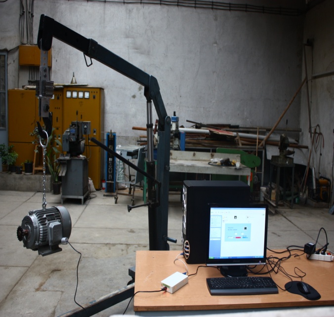 | Figure 5. Laboratory test to study hook peculiarities on the sway angles. |
Experiment was carried out for four different length and weight of hook in four repetitions. In each case, the load was released with zero velocity off a definite location to create the sway. This location was considered on the tip of pump lever which had been adjusted with angle of 30° relative to the longitudinal axis of the crane boom to create the sway in various directions. The sensor of accelerometer was attached to the load for transmitting data to the accelerometer and a computer. The test was accomplished in a time period of 30 seconds. Thus, the output data could be saved in computer after this period. Figures 6 and 7 show the results for minimum and maximum magnitudes of mass and length of hook. The entire repetitions produced already the same results.  | Figure 6. Experimental outcome,effect of hook mass on the sway of payload. |
 | Figure 7. Experimental outcome,effect of hook length on the sway of payload. |
6. Conclusions
In this paper, effect of the crane hook peculiarities including mass and length on sway angles was investigated by use of Lagrange equation and determination of the equations of motion for the system with seven-degrees-of-freedom. Laboratory test was performed to validate the results. Both theoretical and experimental results verify the effect of hook mass on the sway angles. Figure 3 indicates that in almost the entire angles of movement, increasing the mass of hook has caused the pendulum motion of the payload to be suppressed in a shorter time. Figure 6 obtained from laboratory test confirms the theoretical outcomes. The altitude of the wave and time of wave suppression have been reduced in heavier hook. Results indicate that the length of the hook has smaller effect on the sway angles than mass, although the variation of hook length has been carried out in a small range (about 100 mm) .Theoretical results show a depression of sway due to increasing the hook length in most of the movement angles. However, experimental outcome (Figure 7) indicates a distinct but small variation in the increment of sway for shorter hook because in laboratory test, in fact sum of the entire sway angles have been measured instead of considering the sway angles solely.
References
| [1] | Jerman, B., and Kramar, J., 2008, A study of the horizontal inertial forces acting on the suspended load of slewing cranes., Journal of Mechanical Science, 50, 490-500 |
| [2] | Jerman, B., Podrza, j., and Kramar, J., 2004, An investigation of slewing crane dynamics during slewing motion-development and verification of a mathematical model., International Journal of Mechanical Sciences, 46, 729-750 |
| [3] | Posiadata, B., Skalmierski, B ., Tomski, L., 1990, Motion of the lifting load brought by a kinematic forcing of the crane telescopic boom., Mechanisms and Machine Theory, 25, 547-56 |
| [4] | Kim, D., and Singhose, W., 2006, Reduction of double-pendulum bridge crane oscillations. The 8th international conference on motion and vibration control (MOVIC) |
| [5] | Schaub, H., 2008, Rate-based ship-mounted crane payload pendulation control system., Control Engineering Practice,16,132-145 |
| [6] | Neupert, J., Arnold, E., Schneider, K., Sawodny, O., 2010, Tracking and anti-sway control for boom cranes., Control Engineering practice, 18, 31-44 |
| [7] | Khalid, L.S ., Sinhose, W., Dickerson, S., 2007, A controller enabling precise positioning and sway reduction in bridge and gantry cranes., Control Engineering Practice, 15, 825-837 |
| [8] | Wei, L ., Zhixin, W., Baoliang, Q., Shijun, S ., and Caishan, L ., 1993, The mathematical model of the load vibration-sway on fixed type tower cranes.Modelling,Measurement and control., Solid and Fluid Mechanics and Thermics,Mechanical Systems, 51, 1-12 |
| [9] | Kiss, P . Levine, M., and Mullhaupt, P., 1999, Modeling, flatness and simulation of a class of cranes., Periodica Polytechnica, 43, 215-225 |
| [10] | Huilgol, RR ., Christie, JR., and Panizza, MP., 1995, The motion of a mass hanging from an overhead crane., Chaos, Solitons and Fractals, 5, 1619-1631 |
| [11] | Lau, W. S. M., and Low, K. H., 2003, Motion analysis of a suspended mass attached to a crane., Applied Ergonomics, 18, 297-304 |
| [12] | Seto, W., Mechanical vibration, 2nd ed, McGraw-hill International Book Company, New York, 1983 |
| [13] | Thomson, W., and Dahleh, M.D., Theory of Vibration with Applications, 2nd ed, Prentice Hall, New Jersy, 1998 |
 Abstract
 Reference
 Full-Text PDF
 Full-Text HTML