-
Paper Information
- Next Paper
- Paper Submission
-
Journal Information
- About This Journal
- Editorial Board
- Current Issue
- Archive
- Author Guidelines
- Contact Us
International Journal of Mechanics and Applications
p-ISSN: 2165-9281 e-ISSN: 2165-9303
2011; 1(1): 1-11
doi: 10.5923/j.mechanics.20110101.01
Three Dimensional FE Model of Stud Connected Steel-Concrete Composite Girders Subjected to Monotonic Loading
 Abstract
 Reference
 Full-Text PDF
 Full-Text HTML
Amar Prakash , N. Anandavalli , C. K. Madheswaran , J. Rajasankar , N. Lakshmanan
CSIR-Structural Engineering Research Centre, CSIR Campus, Taramani, Chennai, 600113, India
Correspondence to: C. K. Madheswaran , CSIR-Structural Engineering Research Centre, CSIR Campus, Taramani, Chennai, 600113, India.
| Email: |  |
Copyright © 2012 Scientific & Academic Publishing. All Rights Reserved.
Nonlinear behaviour of stud connected steel-concrete composite girders is numerically studied in this paper. Focus of the study is to develop and validate a three-dimensional finite element model. Numerical results are compared with that obtained from an experimental study conducted by authors. Brief description of the experiment to the extent required for validation is provided in the paper. A sophisticated 3D finite element model of the composite girder is developed using ABAQUS software. Nonlinear damage plasticity model is considered for modelling concrete. Suitable interface elements combined with the constraints are used to describe interaction among the concrete slab, steel beam and studs. Besides the interaction between concrete and steel, appropriate value of friction coefficient is also used. Validation of the model is done in terms of comparing the predicted energy absorption capacity, slip at interface, cracking and crushing of the concrete, yielding and local buckling of steel beam flanges with the corresponding values obtained in the experiments. Energy absorption capacity of the composite girder obtained from the finite element analysis corroborated well with corresponding measured values. It is observed that the FE model predicts a conservative value for ultimate load.
Keywords: Steel-Concrete Composite Girder, Shear Studs, FE Model, Concrete Damage Plasticity Model, Response Validation
Cite this paper: Amar Prakash , N. Anandavalli , C. K. Madheswaran , J. Rajasankar , N. Lakshmanan , "Three Dimensional FE Model of Stud Connected Steel-Concrete Composite Girders Subjected to Monotonic Loading", International Journal of Mechanics and Applications, Vol. 1 No. 1, 2011, pp. 1-11. doi: 10.5923/j.mechanics.20110101.01.
Article Outline
1. Introduction
- Performance of steel-concrete composite (SCC) girders for static and dynamic loads depends significantly on force transfer mechanism at the interface between steel beam and concrete[1,2]. Stud connected SCC girders consists of an effective mechanism to resist the shear force at the interface between concrete slab and steel beam[3]. Stud connectors significantly increase the shear resistance of interface and hence assist in increasing the load carrying capacity of the SCC girder through dowel action. It is important to understand nonlinear behaviour of the stud interface in order to exercise control in the design of SCC girder.Nonlinear behaviour of SCC girders has been extensively studied by conducting experiments[4-8] or through numerical modelling[9,10]. Evidence and understanding developed through experiments are made use of to develop and validate sophisticated finite element models[11-13]. Simple analytical models are also available to depict the force transfer mechanism between the concrete slab and steel girder[14-18]. These models are useful to obtain an approximate estimate of the capacity of a SCC girder. Two dimensional finite element model representing a cross-section can be used to study the behaviour of a SCC girder[19-21]. These 2D models, however, impose restrictions on representation of interface and its actual behaviour. Three dimensional models are versatile to represent the actual geometry including the interface behaviour in SCC girders. In fact 3D finite element models are useful for a variety of conditions such as simulation of push-out tests[22-24], analysis of SCC bridge decks[25], and modelling of full and partial shear connection in SCC beams[26]. Combination of solid, shell, beam and link elements enable accurate modelling of interface behaviour besides the actual representation of geometry. In spite of using sophisticated models simplifying assumptions are introduced with the aim to limit the modelling requirements. One such simplification is due to imposing linear relation between stress and strain across the depth of a SCC girder under flexure[27,28]. This implies equal curvature for concrete slab and steel beam which may not be true due to difference in their stiffness. Another common assumption is to neglect the local buckling of constrained steel flange. Notwithstanding these simplifications 3D finite element model[29,30] provide excellent correlation with experimental results on ultimate capacity. Liang et al.[13] used a 3D beam element to model stud shear connectors in their numerical studies. Studs were assumed to connect the mid plane of concrete slab and the top steel flange of the steel beam, both of which were modelled with the shell elements. Equivalent shear connection stiffness was used in the 3D model due to variation in modelled length of shear connector. Quieroz et al.[26] have modelled concrete slab using solid element while elasto-plastic shell element is used to model the steel section. Slab-girder interface has been modelled using nonlinear springs and smeared approach has been adopted to represent steel reinforcement in the slab. This model has failed to capture the concrete behaviour in the vicinity of stud connector. Research publications on stud-connected SCC girders using 3D finite element models are found to be limited. Even among those available, a detailed study that includes contact and interaction among the stud and concrete could not be identified. The present paper contributes to understanding of the nonlinear behaviour of stud connected SCC girder through comprehensive numerical investigations. The paper is focused towards developing a 3D finite element model of stud connected SCC girder and validating it by using responses measured from an experiment conducted by authors. Finite element model of the SCC girder is unique by accounting for local interactions among the studs and concrete slab. Results indicate capability of the 3D model to predict local buckling of the constrained steel beam flange in SCC girder. The finite element model incorporates suitable interface elements in combination with tie constraints to describe structural interaction among the steel components like stud base and top flange of steel beam, stiffener to web and flanges. Concrete is idealized to behave as an elasto-plastic material under compression and linear elastic material upto cracking under tension.Damage plasticity model, which considers cracking as damage, is used to represent concrete. The same material model is used to account for stiffness degradation of concrete due to cracking. The finite element model is validated by comparing critical global and local responses such as energy absorption capacity of SCC girder, deformation, interface slip, cracking and crushing of concrete, yielding and local buckling of girder flanges measured in experiments. The present study proves better performance of the finite element model in predicting energy absorption capacity.
2. Experimental Investigation
- As a part of the present study, experiments were carried out on SCC girder to investigate their flexural behaviour. A series of six large-scale SCC girders were tested under monotonic (quasi-static) and cyclic loading. The test set up for the experimental study is shown in Figure 1.Each specimen was 4 m long simply supported over a span of 3.8 m. Besides reinforced concrete slab, SCC girder comprises of rolled steel beam with workshop welded stud connectors and plate type stiffeners at the ends. The width of the concrete slab was 665 mm. The test setup was basically same for both quasi-static and cyclic loading. The tests were carried out after the concrete had achieved its design strength (cylinder strength, 36 MPa). A hydraulic actuator capable of applying up to a maximum load of 600 kN was used to test the specimens.
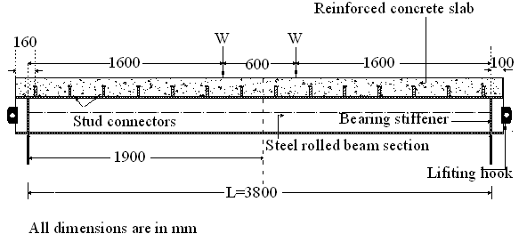 | Figure 1. Details of steel-concrete composite girder specimen. |
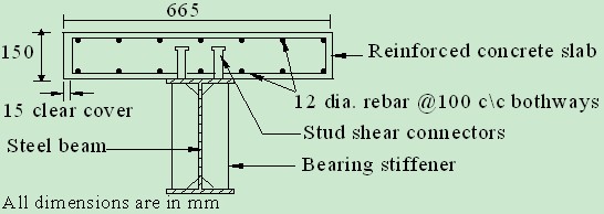 | Figure 2. Cross-section of the steel-concrete composite girder. |
3. Finite Element Model
- Steel-concrete composite girder with a clear span of 3.8 m having simply supported ends is modelled using ABAQUS[31]. The load is applied on the top surface of concrete slab distributed over full width of the girder. Due to symmetry in geometry, loading and boundary conditions only a quarter model is developed as shown in Figure 3. Three coordinate axes X, Y and Z are represented as axes 1, 2, 3 in the model. Symmetry boundary conditions are shown with restrained degrees of freedom.
 | Figure 3. Quarter model of the SCC girder. |
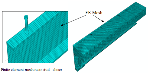 | Figure 4. Finite element mesh of the quarter SCC girder. |
|
|
3.1. Loads
- The concentrated loading (Figure 1) has been modelled as equivalent pressure on the top surface of concrete slab over a contact width of 100 mm at load point location (Figure 3). The load is applied in steps of 10 % of the maximum value.
4. Material Model
4.1. Concrete
4.1.1. Compression Behaviour
- Elastic–plastic behaviour of concrete in compression including strain softening has been modelled according to Carreira and Chu[32]. The model is expressed by following equations:
 | (1) |
 is the compressive stress in concrete;
  is the strain in concrete;
  is cylinder compressive strength of concrete;
  strain corresponding to
 in MPa; and
  is defined as:
 | (2) |
 is considered as 0.002[13]. In the present nonlinear FE analysis, the stress–strain behaviour of concrete in compression is assumed as linear elastic up to 0.4
 . Failure ratio option has been used to define failure surface of concrete. In the present study, ratio of the ultimate biaxial compressive stress to the ultimate uniaxial compressive stress was taken as 1.12. The ratio of the uniaxial tensile stress to the uniaxial compressive stress at failure is maintained as 0.1[13]. Nonlinear stress-strain behaviour of concrete in uniaxial compression and tension used in the study are shown in Figures 5 and 6 respectively.
 | Figure 5. Uniaxial compressive stress-strain behaviour of concrete (using eq. 1 and 2). |
4.1.2. Tension Behaviour
- Stress–strain relationship for concrete in tension assumes that the tensile stress increases linearly with tensile strain up to concrete cracking stress. After cracking of concrete, the tensile stress decreases linearly as the concrete softens. Post peak stress-strain behaviour is defined using tension stiffening option.
 | Figure 6. Uniaxial tensile stress-strain behaviour of concrete. |
4.1.3. Damage Model
- Elastic-plastic response of the concrete is described in terms of the effective stress,
 and the hardening variables,
  and
and  [31]:
[31]:  | (3) |
 and,
and,  ,where,
  is non-negative plastic multiplier and F is yield function both obey the Kuhn-Tucker conditions:
 =0;
=0; ; F. Plastic flow is governed by flow potential G. The Cauchy stress,
  is calculated in terms of the stiffness degradation variable,
 , and the effective stress as:
  | (4) |
4.1.4. Stiffness Degradation
- Evolution equations of the hardening variables in tension
 and compression
  are formulated by considering uniaxial loading conditions first and then extended for multi-axial conditions[31]. As shown in Figure 7, when the concrete specimen is unloaded from any point on the strain softening branch of the uniaxial nonlinear stress-strain curve, the unloading response weakened, due to which the elastic stiffness of the material appears to be damaged (or degraded). Degradation of the stiffness is significantly different between compression (Figure 7a), and tension (Figure 7b). In either case, the effect is more pronounced as the plastic strain increases. The response of degraded concrete is characterized by two independent uniaxial damage variables, dt and dc (both have the value between 0 and 1), which are assumed to be functions of the plastic strains, and field variables.
  | Figure 7. Graphical representation of the damage parameters in relation with uniaxial nonlinear stress-strain behaviour. |
 | (5) |
 and compression
 , are determined using equation (6):
 | (6) |
 | Figure 8. Uniaxial stress-strain behaviour of structural steel. |
4.2. Steel
- Nonlinear behaviour of steel is modelled using elastic and plastic models. The uniaxial tensile stress-strain behaviour of various steels is provided in following sub sections.
4.2.1. Steel Beam and Stiffener
- Elastic-plastic material model is employed based on the nominal stress-strain behaviour of steel shown in Figure 8. The true stress and strain values are given as input to the finite element model.
4.2.2. Stud
- Elastic-plastic bilinear model is used for the steel used in stud connectors. Nonlinear stress-strain behaviour as shown in Figure 9 is provided as input to the model. The yield stress given in Table 1 is obtained based on 0.2% strain criterion.
 | Figure 9. Uniaxial stress-strain behaviour of steel in stud connectors. |
5. Interaction Model
- Mechanical interaction between the stud and concrete surfaces is modelled using friction formulation in tangential direction and hard contact in normal direction to avoid penetration into each other. The penalty method is used for tangential behaviour along with the coefficient of friction as 0.4. For normal interaction, hard contact option is used and the separation was allowed after contact in the interaction model.For interaction between concrete slab and top flange of steel beam the concrete surface is modelled as slave and top flange surface of steel beam is modelled as master. Similarly, the concrete surface around stud is modelled as slave and curved surface of stud connectors as master. Finite sliding along with penalty contact method is used for the interaction between studs and concrete.Welded regions like stud to flange of steel beam and stiffener to web of steel beam were modelled using tie constraints assuming no separation at weld locations. Longitudinal and transverse reinforcement bars are used with embedded region option.
6. Validation of Finite Element Model
- Validation of the finite element model is carried out using the experimental study as described in section 2.0. The energy absorption capacity that is area under load-deflection curve, interface slip variation, stress and strain variation in steel and concrete elements are discussed in following sections. Numerical and experimental results are found to match very well. The ultimate load obtained by the finite element model is found to be only 90% of the corresponding experimental value (550 kN).
 | Figure 10. Load-deflection behaviour. |
6.1. Load-deflection Behaviour
- The numerical and experimental results are compared in the load-deflection plot of the girder shown in Figure 10. It is found that both numerical and experimental load-deflection curves coincide in the initial elastic region upto about 140 kN. This indicates that upto load value of about 25% of ultimate load no degradation occur in stiffness of SCC girder. With increasing load there is almost constant difference in the curve upto a load value of 400 kN and FE analysis shows higher deflection as compared to the experimental. The yield load for the composite girder was determined based on elastic analysis as 360 kN. During experiment, yielding in steel bottom flange has started at about 330 kN. However, flexural tension induced cracking in the bottom face of concrete slab was observed to initiate at a load of about 290 kN. After a load of about 400 kN, the numerical model predicts considerably more deflection than the experimental specimen. Also the descending post peak behaviour is found to have minor differences with that of experiments. This could be due to the bilinear model used for steel. Another possible reason for the difference in load-deflection behaviour may be due to neglecting the contribution of weld collar at the stud bottom. In FE model tie constraint is used for simplicity which does not account for the weld collar contribution in resisting the interface forces. The maximum deflection obtained numerically at mid span is found to be about 136 mm which is closer to experimental value of 138 mm, however corresponding loads are different. It can be seen that the numerically computed deflection is more for load beyond 400 kN as compared with experimental values. This difference can be minimized by considering the contribution of weld collar at the stud bottom and the effects of confinement of concrete. Beyond the peak load, the vertical deflection was found to increase rapidly and, therefore, dial gauges were removed to avoid any damage. However the vertical deflections after peak load were measured with the help of steel ruler. Due to this, few points just after the peak could not be recorded. Post peak response of the composite girder exhibited large displacement at failure. In experiment, the SCC girder was considered to have failed when concrete at top, near support got crushed and the load reduction (370 kN) at this stage was about 30% of peak load recorded (550 kN).
 | Figure 11. Slip behaviour at steel-concrete interface. |
6.2. Interface Slip Behaviour
- Predicted slip behaviour at the steel-concrete interface near yield load of SCC girder and at maximum load are shown in Figures 11(a) and 11(b), respectively. Interface slip is computed as difference in horizontal displacement in longitudinal direction between the adjacent finite element nodes in concrete slab and top flange of steel beam.
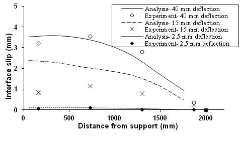 | Figure 12. Comparison of interface slip. |
 | Figure 13. Flexural cracks and location of concrete crushing. |
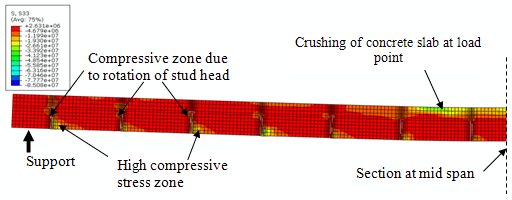
6.3. Cracking and Crushing in Concrete
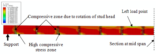
- In the experiment, flexural cracks started appearing at bottom face of concrete slab as shown in Figure 13. These cracks further grew upward with the increase in load till crushing at top of the concrete slab near the left side load point occurred. Stress contours shown in Figure 14 gives the damage due to compression at the bottom of the stud shank near yield load. A similar trend is observed till the ultimate load is reached (Figure 15).In the finite element analysis, top face of the concrete slab exhibited crushing near mid span for compressive stress in concrete of about 36 MPa and strain of 2030 µε. In experiment also similar values were obtained.
6.4. Yielding and Local Buckling in Steel Beam
- Yielding of bottom flange was observed in the rolled steel beam section. The predicted yield load capacity based on elastic analysis for the SCC girder was found to be about 380 kN and experimentally yielding in bottom flange was observed at load of about 330 kN.
 | Figure 14. Stresses in concrete slab near yield load. |
 | Figure 15. Stress in concrete slab near ultimate load. |
 | Figure 16. Local buckling of top flange in steel beam at failure load (Experimental). |
 | Figure 17. Local buckling of top flange near maximum load (FE Model). |
 | Figure 18. True strain contours at ultimate load. |
 | Figure 19. Stress distribution in stud shank. |
6.5. Stud Shank Response
- True strain contours as shown in Figure 18 exhibit that there occurs a pattern in the strain (or stress) within the height of the stud. The contours indicate the inflexion between compressive and tensile strains which indicate that stud tends to deform in double curvature. This observation is important to understand the damage zone in the vicinity of studs. It can be stated that stud can cause damage due to the compressive forces at diagonally opposite faces.Figure 19 shows that the stress in stud shank varies along its height as well as perimeter. Due to this nature of tensile and compressive stresses, the stud tends to deform in double curvature. Understanding of deformation behaviour of studs is useful in the design of SCC composite girders
7. Conclusions
- A three-dimensional finite element model of SCC girder is developed using the commercial software ABAQUS. The model has proved to be effective in terms of predicting the energy absorption capacity, load-slip at the steel-concrete interface, shear force carried by the studs and the mode of failure (stud failure or concrete crushing). It is also able to investigate SCC girders with either full or partial shear connectionThe following conclusions are drawn from this study 1. Damage plasticity model which is implemented in ABAQUS is found suitable for the modelling of cracking and crushing of concrete. 2. It is found that energy absorption capacity of the SCC girder predicted by the analysis is nearly same as obtained from experiment. It is also observed that present model predicts conservative value for ultimate load.3. Interface slips obtained from the present model are found to match well for linear elastic and ultimate deflection values. However, predicted interface slip corresponding to deflection at yield load show minor deviation though both had the same trend.4. Locations of high stress concentration zones near studs and crushing of concrete are found to be predicted exactly by FE analysis. 5. Location of local buckling in steel beam flange was also captured accurately by the FE analysis.6. Implementation of contact and interaction features in the modelling provided more realistic behaviour of SCC girder7. The proposed three-dimensional FE model provides the framework for developing more realistic model to capture the intrinsic behaviour of SCC girders. It is otherwise difficult, if not impossible, to obtain using experimental studies, due to cost and time factors. 8. The FE analysis provides a better insight into realistic behaviour (including the detection of local aspects of behaviour e.g., local deformations of steel beam and cracking and crushing of the concrete slab). The inflexion in stress and strain values for concrete is observed in the vicinity of stud specifically along the height of studs.
ACKNOWLEDGEMENTS
- The authors wish to acknowledge the help rendered by staff of Advanced Materials Laboratory and Structural Testing Laboratory of CSIR-SERC in conducting the experimental study. This paper is being published with the kind permission of Director, CSIR-Structural Engineering Research Centre, Chennai, India.