Richard de Medeiros Castro1, Alexandre da Silva Rocha2, Elvys Isaías Mercado Curi1, Fábio Peruch1
1Department of Mechanical Engineering, Faculty SATC, Criciúma-SC, Brazil
2Department of Metallurgical Engineering, UFRGS - Federal University of Rio Grande do Sul, Porto Alegre-RS, Brazil
Correspondence to: Richard de Medeiros Castro, Department of Mechanical Engineering, Faculty SATC, Criciúma-SC, Brazil.
| Email: |  |
Copyright © 2018 The Author(s). Published by Scientific & Academic Publishing.
This work is licensed under the Creative Commons Attribution International License (CC BY).
http://creativecommons.org/licenses/by/4.0/

Abstract
In order to obtain a wear and oxidation resistant surface, hydraulic cylinders are commonly coated with electrodeposited hard chromium. However, due to the wear, this type of coating exhibits a gradual increase of the bearing area for the sealing elements, interfering in the lubrication of the hydraulic rod, causing damage to the sealing elements and, consequently, oil leakage. Currently, the High Velocity Oxygen Fuel (HVOF) process appears as an alternative coating technique to Hard Chrome Plating, using composites (metal-ceramic), which provide low wear rates and a low friction. This work aims to compare the mechanical and tribological properties of hard chrome plated and WC-CoCr HVOF coated AISI 1045 steel for the use as hydraulic rods. The selected coatings thickness was in the order of 100-170 μm aiming to meet best wear test conditions, to facilitate the analysis of the microstructure, and to obtain better results regarding the hardness of each coating. Roughness measurements, hardness, bending and wear tests, including the measurements of friction coefficients were carried out for the coatings. Additionally, a microstructural analysis was performed by optical and Scanning Electron Microscopy (SEM) supported by Energy Dispersive Spectroscopy (EDS). The results indicated superior properties of the WC-CoCr HVOF coated steel in comparison to the chrome hard plated one, especially regarding roughness, friction and wear.
Keywords:
Wear, Friction, Thermal Spraying, WC-CoCr, Hydraulic Rods
Cite this paper: Richard de Medeiros Castro, Alexandre da Silva Rocha, Elvys Isaías Mercado Curi, Fábio Peruch, A Comparison of Microstructural, Mechanical and Tribological Properties of WC-10Co4Cr - HVOF Coating and Hard Chrome to Use in Hydraulic Cylinders, American Journal of Materials Science, Vol. 8 No. 1, 2018, pp. 15-26. doi: 10.5923/j.materials.20180801.03.
1. Introduction
As a power transmission element, the hydraulic cylinder can continuously transmit a wide range of power, which can be controlled easily and with accuracy. Its application usually occurs under difficult working conditions, in mining, offshore, aviation, agricultural equipment, and metallurgy. Hydraulic rods are normally exposed to extreme and hostile environments such as seawater or high temperature, and environments with a high amount of solid particles, as is the case of mineral extraction, that lead to rapid wear of the cylinders [1]. Consequently, the rods of the hydraulic cylinders are coated with a layer of protective material, usually hard chrome. The purpose of this coating is to improve surface characteristics and mechanical properties such as surface hardness, corrosion resistance, wear resistance, and even reduce friction. However, the electrodeposited hard-chrome layer, as the wear progresses, causes a gradual increase of the supporting area to the sealing elements and guides. This interferes directly in the lubrication of the rods, causing damage to the sealing elements and promoting fluid leakages. This is because the roughness peaks are broken during slippage and, thus, the height of the valleys decrease dramatically, not holding the lubrication oil anymore. Another problem in the use of Hard Chrome Plating is the presence of Cr6+ hexavalent chromium in high levels, leading to high carcinogenic and environmental contamination [2, 3]. Nowadays, several processes are under consideration as alternatives to replace Hard Chrome Plating. The main ones are Chemical and Physical Vapor Deposition (CVD and PVD) and Laser Cladding but the main disadvantages of these processes are the difficulties in the retreatment of the parts. Recent publications have shown that the High Velocity Oxygen Fuel (HVOF) technique can be used both for the manufacture of new coatings and for the recovery of rods that have already been used [4, 5]. An advantage of the HVOF process is that is produces a coating with high density, low oxide content and good adhesion [1-6]. Driven by the need to improve the wear of the components, some sealing industries are looking for new technologies to establish themselves in the market. They also allocate all set of actions carried out by environmental strategists on alternatives to hard chromium. A survey published by the Aerospace Sealing Technology News (ASTN) in 1999 presented results to the US Air Force over alternatives to Hard Chromium Plating in fluid power system components. In this study the WC-CoCr HVOF coatings have been evaluated, demonstrating excellent results [7, 8].The characteristics most often used to describe the topography of a surface are the roughness parameters Ra, Rz and Rmáx (μm), defined in DIN/ISO 4287. However, for hydraulic cylinders, it is necessary to know the parameter Rmr (%), which determines the support area for the seal. In several cases, different surfaces can have similar Ra values but, for other roughness parameters, totally different values can be found. According to Steep and Wüstenhagen (2006), 80% for Rmr should be an optimal value for hydraulic cylinders [9, 10].With the objective of identifying the performance of the WC-CoCr coating and establishing a comparison with the traditional hard chromium coating, the metallurgical, mechanical and tribological properties of an AISI 1045 steel used in hydraulic cylinder rods were evaluated. The tests were selected according to the conditions under which the coatings would be subjected. The coating thickness selected was of the order of 100-170 μm in order to meet the best wear test conditions, to facilitate the analysis of the microstructure and to obtain better results in relation to the hardness of each coating. Roughness, hardness, bending and wear measurements were performed, including the coefficient of friction measurements for both coatings. Additionally, the microstructural analysis was performed by optical microscopy and scanning electron microscopy (SEM) supported by energy dispersive spectroscopy (EDS). The bending tests were done according to ASTM E290, common in weld coatings, in order to identify the crack density for each bend angle [12]. The tribological evaluation was performed by the abrasive wear method, a mechanism that normally occurs during sliding of the hydraulic rods, so was selected the rubber and sand wheel method [13]. However, to identify and provide results on the coefficient of friction for both coatings, the pin on disk method was chosen [14].
2. Experimental Procedure
2.1. Characteristics of the Material of Substrate
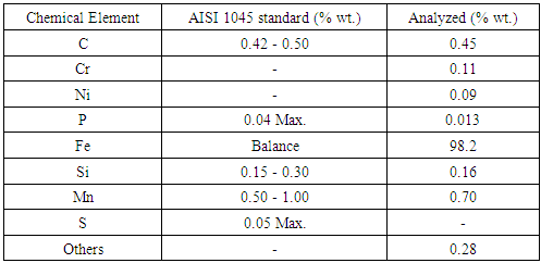
Specimens of AISI 1045 steel in the as delivered state (as hot-rolled), used to obtain the chemical composition of the material of substrate, were manufactured with 25 mm of diameter and 30 mm of height. The chemical composition presented in Table 1 was obtained using mass atomic spectrometry. After preparation, the samples were coated with two different types of coating: Hard Chrome, which is an electroplating process, and WC-CoCr - HVOF which is a thermal spraying process.Table 1. Chemical composition of the AISI 1045 used as substrate
 |
| |
|
2.2. Electroplating Process - Hard Chrome
Before hard chromium deposition, specimens were sandblasted to obtain an Ra roughness of 0.28 μm and then cleaned for improved adhesion. Basically, the process of cleaning the surface of the base material was carried out by chemical means, using a solvent, by cold degreasing and an aqueous solution to remove oxide layers. The roughness of the substrate in AISI 1045 in hard chromium deposition is lower than those used by HVOF. This average roughness value is necessary so that after the hard chromium deposition does not appear the scratches of the machining.The chrome plating procedure occurred as follows: the specimens were immersed in a reservoir containing the Cr2O3 compound, dissolved in water. H2SO4 acid was added to this solution to act as a catalyst. The specimens (cathode) were connected at the negative pole and the positive pole (anode) was a sheet metal made of inert metal (93Pb7Sn). The final chrome layer thickness was of approximately 101 ± 3 μm with a deposition time of 2 hours. After of hard chrome deposition a fine machining process, with sandpaper and polishing was done to remove the more peaks, leaving with the surface finish used on hydraulic rods.
2.3. Thermal Spray Process (HVOF) – WC-CoCr
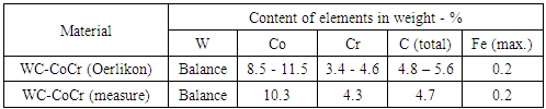
Before thermal spraying deposition, surfaces were grit-blasted with aluminium oxide (Al2O3) and cleaned with isopropyl alcohol in order to remove the impurities and obtain adequate roughness for the adhesion of the coatings, remaining with a roughness Ra of 6.4 μm. This roughness Ra difference, 0.28 to 6.4 um, is justified by the need for mechanical anchoring of the coating to the substrate by HVOF, requiring greater surface irregularity to fix the thermal spray coating.The spraying equipment was an HP-HVOF and commercial powder of WC-CoCr with a density between 4.8 to 5.0 × 10⁴ kg/m3 was used for deposition. Fig. 1 (a) shows the morphology of the as-received powder under a scanning electron microscope (SEM) with particle sizes in the range of 45 to +15 μm. The chemical composition of the powder was confirmed by electron dispersive spectrometer (EDS) analysis (Fig. 1 b). In the present study, WOKA 3653 powder was commercially provided by the company Oerlikon Metco and the chemical composition of this product is compared by measuring EDS (Table 2).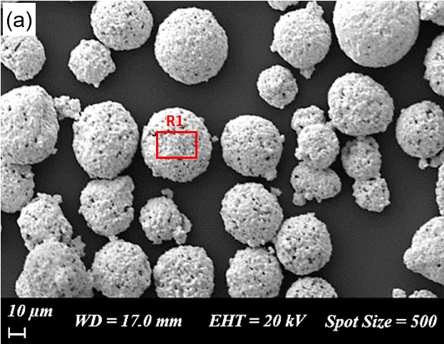 | Figure 1. SEM micrographs of WC-CoCr powder |
Table 2. Comparison of the Chemical Composition of WC-10Co4Cr
 |
| |
|
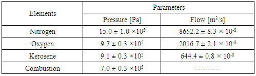
The parameters for HVOF spraying are presented in Table 3. The distance between the torch and the specimens was set at 305 mm with a gun size of 152.4 mm and the powder feed rate was set at 15 × 10-4 kg/s. At the end of the coating deposition process, the specimens were submitted to the grinding and polishing process, resulting in an average roughness Ra of 0.12 μm, used for hydraulic cylinder rods.Table 3. Thermal spray deposition parameters to WC-CoCr
 |
| |
|
The HVOF coatings had a final thickness of about 167 ± 7 μm with a deposition time of 5 minutes in total. The coating thickness was controlled by a defined number of passes by the substrate and according to the parameters of Table 3.
2.4. Microstructural Characterization and Hardness Test
For the microstructural characterization of the coatings and hardness tests (hardness profiles), specimens were cut in the cross section, then sanding and polishing. Vickers HV0.01 microhardness profiles with automatic loading and unloading rate and dwell time of 15 seconds were obtained by using a HMV-02 TADW-SHIMADZU microhardness tester, and tests were based on ASTM E 384-89 [11]. For each microhardness profile, four indentations were created in the substrate and twelve in the coating. This was repeated for three different regions of each specimen. An average microhardness profile was calculated from the 3 obtained profiles. Optical microscopy analysis was carried out in an OLYMPUS microscope model BX 51M with non-etched samples.
2.5. Guided Bending Test
Guided bending tests were carried out according to the procedures of ASTM E-290, using a Shimadzu® universal test machine, model AG-X plus 100 kN [14]. A sketch of the test apparatus is shown in Fig. 2. Specimens were bent to 24, 90 and 180° bending angles around a mandrel with a diameter of 15 mm and an approximate feed speed of 10 mm/min was used. At each test, the load was released, and the bended sample retracts, so that the final permanent angle of the tested specimens is smaller than the angles tested. In this test condition, the coating receives efforts of tension and compression. The specimens evaluated were strips with 50 mm of width and 100 mm of length, all with a thickness of 3 mm. The bending resistance and adhesion of WC-CoCr and hard chrome coatings were evaluated by analyzing the formed cracks on the specimens after the bend.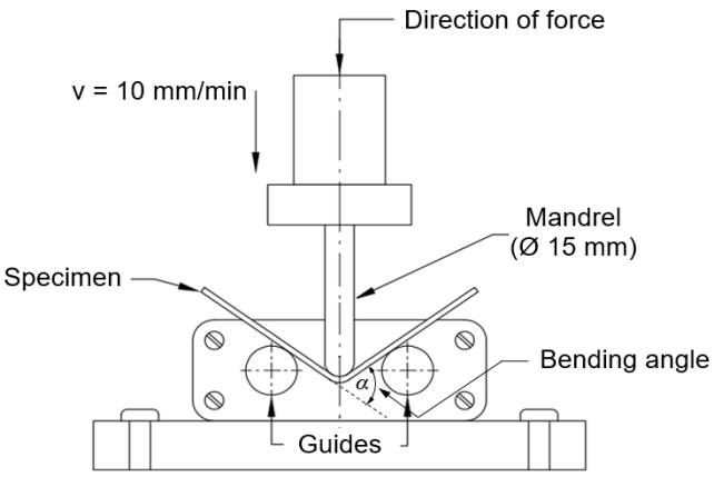 | Figure 2. Principle of the bend test |
After the bending test was performed for each angle, measurements and identification of cracks were carried out using a digital microscope with a magnification of 500 x. For each test specimen, the lengths of 20 cracks were measured to obtain a mean and a standard deviation at each angle, as shown in Fig. 6.
2.6. Wear and Friction Tests
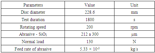
In order to characterize the wear and friction properties of the coatings, two different methods were employed: rubber and sand wheel wear test and pin-on-disc wear test [13, 14]. For the rubber and sand wheel wear test, the procedure A of the ASTM G65 standard was used. This test was used because it would simulate the worst abrasive wear condition a hydraulic rod would have. The test conditions are summarized in Table 4. This is a relatively severe test which will rank materials abrasion resistance. The wear response (loss of volume) was obtained according to Equation 1. The weight loss was measured using an electronic balance with 0.1 mg in accuracy. The wear tests were performed using the parameters of Table 4.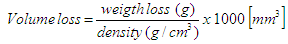 | (1) |
Table 4. Parameters of wear tests: ASTM G65
 |
| |
|
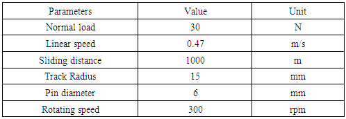
The friction measurement was performed using the procedures of ASTM G99 through the pin on disk test. The friction tests were performed using the same parameters of Table 5 for hard chromium and WC-CoCr coatings. For the friction test, a tungsten carbide sphere was used as the pin, with an average hardness of 1376 HV0.01/15, and a disc with 50 mm diameter. The experimental results of this wear test were determined by means of a profilometer model XP-2 from AMBIUS Technology, evaluating the average removed volume after five measurements by specimens. Additionally, the friction coefficients were monitored during the tests.Table 5. Parameters of wear tests: ASTM G99
 |
| |
|
To characterize the WC-CoCr coatings and to identify the wear micro mechanisms after rubber and wheel testing, Scaning Electron Microscopy equipped with Energy Dispersive X-ray (SEM-EDS) was used. The scanning electron microscope was an EVO MA 10 - ZEISS equipped with u QUANTAX. The surface roughness evaluation was performed before and after the rubber and sand wheel wear tests, using an SJ-210 roughness meter of Mitutoyo, with the Ra, Rz and Rmax recorded in μm and Rmr recorded in percentage, obtaining contact area of support the seal.
3. Results and Discussion
3.1. Microstructure and Hardness of the Coatings
The microstructures of the WC-CoCr coatings are shown in Fig. 3 and Fig. 4. A lamellar structure, typical of HVOF coatings was observed, containing a discrete oxide film in the lamella boundaries and a low number of pores [15]. 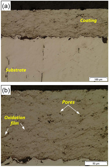 | Figure 3. Micrographs of the WC-CoCr: (a) 200x and (b) 500x. Not etched |
The level of porosity indicated in Fig. 3 (b) was evaluated by image analysis (software Image-Tool). The tungsten carbide-based coatings had a mean porosity of 1.0% with a standard deviation of 0.26%, which is in accordance with the criteria specified by the powder manufactures for this kind of coating (Oerlikon Metco) that establishes a mean porosity of less than 1.0%. In Fig. 4 (b), microcracks can be observed in the hard chrome coating. According to the literature, electrodeposited hard chromium coatings exhibit this micro-cracked morphology as a consequence of residual stress relief [16]. These aligned cracks facilitate the entry of oxygen to the substrate, easily causing oxidation which leads to a very rapid deterioration of the hydraulic component [17]. However, the cracks can be positive when controlled the quantity, as it would aid in the lubrication of the rods.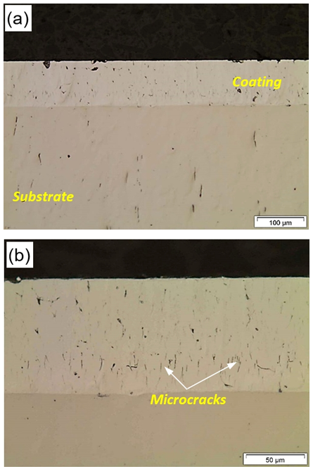 | Figure 4. Micrographs of the Hard Chrome: (a) 200x and (b) 500x. Not etched |
The WC-CoCr coating had an average thickness of 167 μm, with a standard deviation of 7 μm. On the other hand, the hard chrome coating had an average thickness of 101 μm with a standard deviation of 3 μm. The lower standard deviation in the thickness indicates that there is a greater regularity in the hard chromium electrodeposition process compared to the HVOF process. In Fig. 5 Vickers microhardness profiles for the two different coatings are presented.A larger hardness dispersion for the WC-CoCr is seen due to its heterogeneous microstructure (see Fig. 3) in comparison to hard chrome coating. Some studies show that the coatings sprayed with WC-based materials are described as metal-ceramic composites, and the microhardness values found are influenced by each microconstituent [18]. The average value for the coating deposited by HVOF was in the order of 1256 HV0.01, while the value for the electrodeposited chromium was of 952 HV0.01.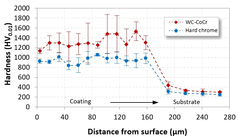 | Figure 5. Microhardness profiles of the coatings |
3.2. Bend Test - Analysis of Cracks and Delamination
The three-point bending test performed according to ASTM E-290 is an usual test to evaluate the adhesion of the coating to the substrate, i.e., to check if cracks and/or peeling of the coating will occur [12]. In this work, the specimens made of AISI 1045 steel are bended and the coatings on the surface are subjected to tensile and compression stress according to the specimen’s side (upper or lower). After the bending tests were performed in 24, 90 and 180 degrees, the cracks and delamination of the coatings were analyzed quantitatively and visually, according to Fig. 6.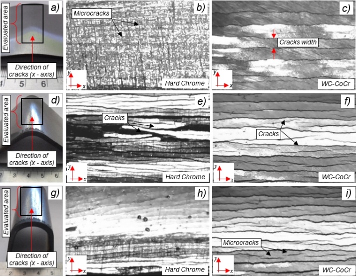 | Figure 6. Results of the bend test: (a, b, c) 24°, (d, e, f) 90° and (g, h, i) 180° |
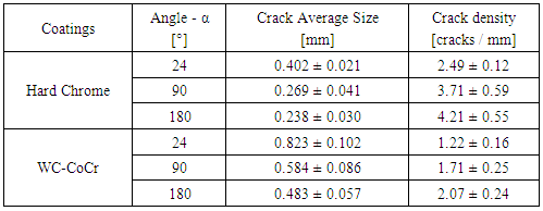
After the bending test, almost all the coatings remained adhered to the substrate with no spallation or peeling phenomena. However, all coatings presented cracks. In the case of the hard chrome coating, the microcracks were in higher quantities than for WC-CoCr, and they very heterogeneous in size. Previous research has pointed out that higher bending angle values increase the damage level with an increase in cracking density [19]. Also, with hard chrome coating, spalling was observed at a 90° bend angle, influenced by the partial breakage of the substrate (see Fig. 8). However, for HVOF coating, the distance between the cracks is greater due to the lower adhesion force between the coating and the substrate. The adhesion process of the tungsten carbide to the substrate results from the impact shrinkage process, being related to a mechanical process of anchoring whereas in hard chrome it occur a electrolytic adhesion.The results of the bending tests are summarized in Table 6. In Fig. 7, the density of the radial cracks is presented as a function of the bending angle, proving that there is a linear relationship between bend angle and radial cracks size. For smaller bend angles, the distances between the cracks are larger, than with a larger angle. Cracks occur in proportion to the bend angle. In general, the failure mechanisms were similar for both coatings, but with longer cracks in the case of hard chrome and also a faster increase in crack size with decreasing bending angle (higher inclination of the curve in Fig. 7). It should be noted that these tests are intended to characterize coatings under extreme conditions that would hardly be required for hydraulic cylinder applications. Fig. 8 (a) and (b) show the failures in the edge of the specimens.Table 6. Influence of bending angle on the frequency of cracks
 |
| |
|
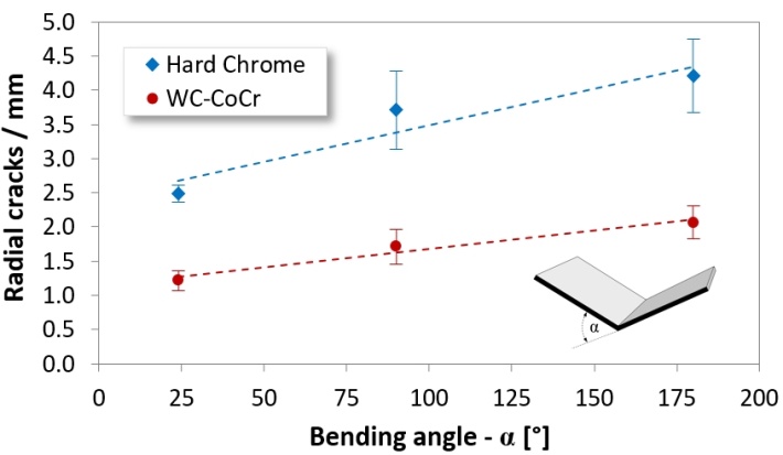 | Figure 7. Influence of bending angle on the frequency of radial cracks |
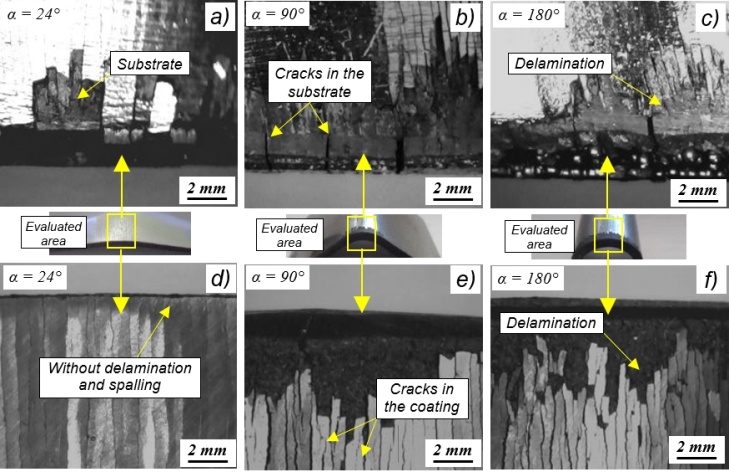 | Figure 8. Macrographic images of specimens for identification of failures on the edge for each bend angle: (a, b, c) Hard Chrome and (d, e, f) WC-CoCr |
Fig. 8 shows the behavior of the coatings in regions considered to be critical, i.e., at the edge of the specimen, where the coating is not supported on the side. Failure mechanisms, such as cracking, delamination and spalling have occurred in this area. A crack initiation was also observed on the substrates at 90 and 180° bending angles, both for hard chromium and WC-CoCr. For a 24° angle with the WC-CoCr coating, no critical failure mechanisms were found, only microcracks that had been observed before, in Fig. 6.
3.3. Friction and Wear Performance
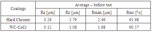
Evolution of the friction coefficient and wear rate for the coatings were evaluated by carrying out tests according to ASTM G99 and ASTM G65. During the polishing of the specimens, the initial roughness was controlled to avoid exceeding the Ra value of 0.8 µm so that the roughness does not influence the surface cracks and the wear rate. Table 7 presents the initial roughness values for the established parameters of these surfaces.Table 7. Measurement of initial roughness of specimens
 |
| |
|
First, the results of the pin on disc are presented for three specimens of each coatings. During the tests, the evolution of the friction coefficients for the two coatings was evaluated (Fig. 9). The hard chrome coating showed an unstable friction coefficient from the beginning of the test. This instability is explained by plastic deformation contribution in the wear mechanism for this coating, observed in Fig. 10. Cancundo (2009) further justifies that, in the beginning of friction tests, a zone of instability occurs, i.e., the friction mechanisms are basically originated by the adhesion phenomenon [20]. The frictional force of the relative movement between the pin and the disk should be sufficient to overcome the inertial force and then the opposition to the motion generated by the initial peaks of roughness. These mechanisms were more evident in the hard chromium coating, identified up to the first 100 m of sliding, according to Fig. 9 (a). Blau (2005) states that this temporary fluctuation is a phenomenon called running-in, historically presented by Abbott Firestone in 1933. The author explains that this initial instability of the coefficient of friction in time not only has relation to aspects of asperities but also occurs in the materials adjacent to the surfaces, such as elastic and plastic irreversible deformation. During that deformation process, changes in crystallographic orientation and the state of work hardening (especially in metals) can occur [21]. Debris can accumulate, and interfacial transfer can occur. Therefore, not only do the shape, texture, and roughness of the surface features change but their substructure and micro-mechanical properties do as well, and this can best justify the region of initial instability.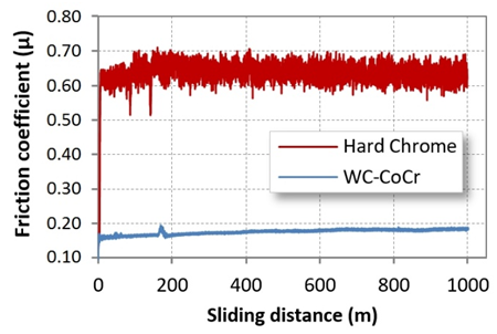 | Figure 9. Results of pin-on-disc test for the coatings: evolution of the friction coefficient |
However, in the WC-CoCr coating, these phenomena were practically not observed. Almost throughout the whole test time, material removal from the coating surface in the form of chips was observed. In the WC-CoCr coating, there was a stabile behavior of the coefficient of friction, characteristic of a lubricated sliding, which was justified by the detachment of fine reddish-brown particles. According to Fang (2009), the low friction of WC-CoCr is due to the formation of oxides particles (WO3) that have lubricating properties, resulting in lower friction coefficients [22, 23]. Fig. 10 shows the wear tracks formed from the friction tests.The first observation is that for the same pin diameter used in tests, the tracks showed different widths. This fact is associated with the high hardness of the spray coating in comparison to the chrome coating, which inhibited plastic deformation and surface material pull-out. In the WC-CoCr coating, only a mild wear path was observed. However, for hard chrome, the wear mechanisms such as plastic deformation and micro-cutting are confirmed by Fig. 10 (a) and 10 (b), respectively.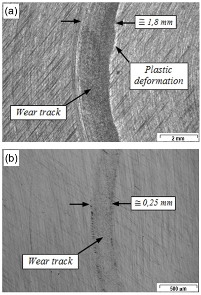 | Figure 10. Wear tracks for coatings: (a) Hard chrome and (b) WC-CoCr |
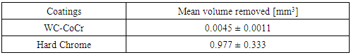
Also, Fig. 11 shows the significant difference of wear depth relative to the surface. For the carbide-based coating, the value was of 0.28 μm and, for hard chrome, this value exceeded 10 μm. According to Table 8, it is observed that the WC-CoCr test samples showed greater regularity in their values in relation to the volume of removed material. Considering the methodology used to quantify the volume withdrawn from the material, the hard chromium presented an approximate amount of removed material 212 times higher than that of the WC-CoCr coating, for a selected line width and its mean radius.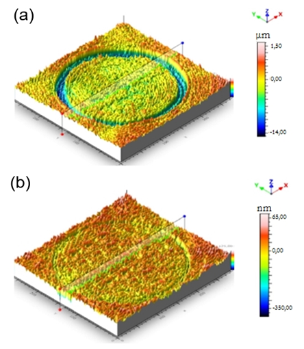 | Figure 11. 3D topography of surface (True Map software): (a) Hard chrome and (b) WC-CoCr |
With the top images of the surfaces, created with 2D/3D profilometry, it was possible to estimate the wear volume by the average profile of each coating, as presented in Table 8.Table 8. Removed material volume of coatings quantified by profilometry
 |
| |
|
For hard chrome, the mean width of the track was approximately 1.8 mm, while for WC-CoCr it was 0.25 mm. According to Bailey (2011), the high wear on electrodeposited hard chrome coating is justified by the density of microcracks presented by the hard chromium coating [17]. This method of measurement did not consider plastic deformation occurring during sliding in the hard chromium coating. However, this result was important to show only one qualitative on the WC-CoCr coating, confirmed also later by the results ASTM G65 test, Fig. 16.After the friction tests, the coatings were subjected to the abrasive wear test using dry sand and rubber wheel. To understand the wear behaviour, the worn coatings were examined using SEM. Fig. 12 and 13 shows the worn surface of each coating wiped by rounded silica sand (SiO2) of 250-300 μm after 30 minutes, shown in two levels of magnification.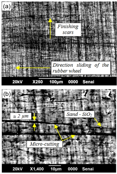 | Figure 12. Surface of hard chrome coated surfaces after wear test. No etched |
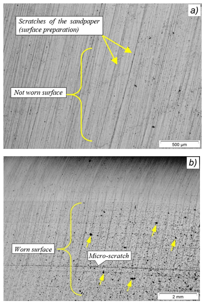 | Figure 13. Microstructural analysis of the WC-CoCr surface at different magnifications: a) not worn surface and b) worn surface |
In Fig. 12 (b), scratches with a width of approximately 2 μm in the sliding direction are seen. This characterizes the action of a micro-cutting mechanism in the surface of the hard chrome. It is also important to note the concentration of sand particles (SiO2) embedded in the tested surface. Fig. 13 shows the surface of the WC-CoCr before the abrasion test and after the abrasion test for the worn and not worn regions.After the abrasion test, the WC-CoCr micrograph reveals carbide removal (marked by arrows in Fig. 13 b). However, with a reduction of ploughing mechanisms, compared to the hard chromium coating. The evidence, even when punctual, of the WC matrix pull-out is visible, and occurs due to the low hardness of the binder (Co). Removal of cobalt leads to a lack of bonding material, eventually resulting in carbides being plucked from the surface [24-26]. Carbide removal is evidenced by the increase of the roughness Ra (Table 9) and by the images produced with SEM-EDS analysis. Additionally, Fig. 13 (b) showed some micro-scratches from the test process but with extremely small track width dimensions (approximately 0.033 μm) compared to hard chrome. Figures 14 and 15 show the SEM-EDS analysis. Fig. 14 (a) shows the coating’s topography; Fig. 14 (b) shows the splitting of the WC matrix; Fig. 14 (c) shows microcracks; and in Fig. 14 (d) shows a remaining grain of sand resulting from the sandblasting process. 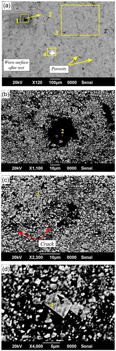 | Figure 14. SEM micrographs after abrasive wear test in WC-CoCr specimens. a) worn surface after test, b) splitting of the WC matrix, c) crack and d) grain of sand |
The first observations obtained by SEM of the specimens sprayed with WC-CoCr (Fig. 14 a) showed a high-density coating characteristic of the HVOF process, although porosity is present, as a characteristic of the HVOF process. Fig. 14 (b) shows a structure with a pull-out characteristic of the WC matrix (hard phase), which was then confirmed by EDS analysis at this point (point 2). Cracks were detected in the longitudinal direction of the sprayed layer (Fig. 14 (c)). Usually, this defect is related to incorrect procedures in the preparation of the surface for the wear test, as high speed and force used in the sanding and polishing of the specimens. Fig. 14 (d) shows an SiO2 particle, which was the abrasive material used in the wear tests. The same image shows, even after the cleaning performed to obtain the images, that a small particle of silica of approximately 10 to 15 μm remained embedded in the surface of the coating. Fig. 15 shows the composition of the elements identified by SEM at the points indicated in Fig. 14.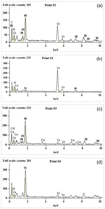 | Figure 15. EDS patterns of the four points analyzed for WC-CoCr coatings: (a) point 1, (b) point 2, (c) point 3 and (d) point 4 |
In order to identify the defects produced in the WC-CoCr tests, images were captured at the points 1, 2, 3 and 4 of the microstructure. For the point 1 in Fig. 15 (a), the EDS spectra identified particles containing carbide and chromium, which are main elements of the sprayed coating, confirming it was a pore. At point 2, a large concentration of chromium was found and a smaller amount of cobalt. It is estimated that, with the sliding of the SiO2 grain particles, pull-out of hard WC particles occurred, with only residues of the CoCr binder matrix remaining. At point 3, a coating region containing the WC-CoCr alloy was also identified in higher concentration. Point 4 revealed the presence of the silicon element present in the abrasive material (SiO2), which means that, at some points, the abrasive material remained in the coating.The tracks characteristic of the abrasive test made by rubber wheel and sand, as well as the wear volumes of the tested coatings, are shown and quantified in Fig. 16.The hard chrome specimen (Fig. 16 a) shows a more visually pronounced wear than the WC-CoCr specimen. In Fig. 16 (b) the HVOF coating presented a higher performance than that of the hard chrome, with volume removed of 2.2E-10 m3 and 14.8E-10 m3, respectively. The wear rate occurs due to the higher difference in hardness between the abrasive material (SiO2, HV0.01 ≈ 1100) and hard chromium (HV0.01 ≈ 952). According to the literature, this would lead to higher plastic deformation increasing the removed material rate [27]. For the WC-CoCr coating, a higher hardness (1256 HV0.01) was identified than that of the abrasive material, resulting in a low volume of removed material.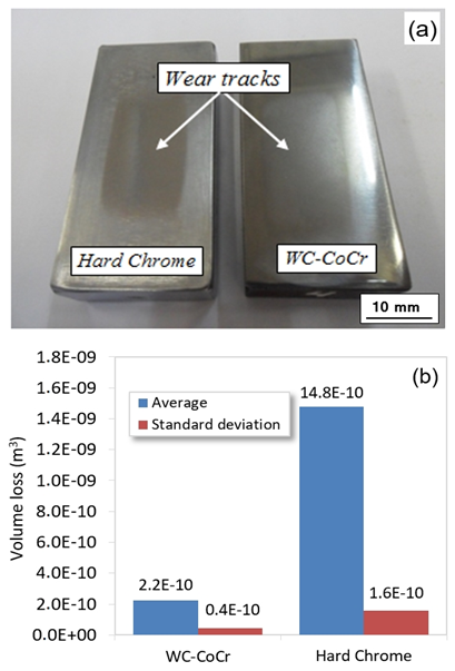 | Figure 16. Results of wear test - ASTM G65-00: (a) Tracks characteristic of the test and (b) mean of the removed volume according to equation 1 |
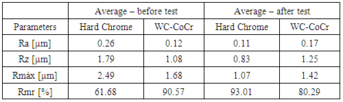
To evaluate the surface finishing of the coatings after testing, roughness was measured. The comparative values of the measurements are shown in Table 9. Based on the presented results, it is possible to state that the WC-CoCr coating presented better performance in relation to the main parameters, Ra and Rmr, because was found the best indexes applied to the sealing surfaces in application of hydraulic cylinders [2].Table 9. Measurement of roughness before and after the wear test
 |
| |
|
It was observed that an increase in roughness values (Ra) occurred for WC-CoCr coatings. This increase occurs due to the pull-out of carbides (appearance of pores) seen in the SEM images, Fig. 14 (a) and (b). Koutsomichalis et al., (2017) describe the phenomenon of pull-out of carbides in wear tests [28]. However, for the hard chrome coating, the Rmr values would be not promising for hydraulic sealing applications due to its polishing, observed by the Ra drop and the Rmr increase in relation to the values recommended in the literature [9-10], which should be around 80% while the observed values after the wear tests are of 93%. The polishing effect would cause the deformation of the sealing member due to the difficulty of lubrication by the low levels of valleys on the surface. However, for the Ra parameter, the chrome coating still appears within the limit range for sealing surfaces.It is important to point out that these results alone do not define an ideal condition for surfaces applied to hydraulic seals. Other factors in actual working conditions for the hydraulic rods will also be important in determining a new coating, and it is important to obtain data from dynamic tests of rods and hydraulic sealing behavior measuring the leakage rates.
4. Conclusions
The microstructure of the WC-CoCr coating showed a discrete oxide film between the layers with low porosity (<1.0%). Moreover, the sprayed coating presented high hardness, of the order of 1250 HV0.01/15, but with a higher standard deviation when compared to hard chromium coating, which presented microcracks in the analyzed layer. This shows that the electrodeposited process contributes and anticipates the abrasive wear and the oxidation of the base material. However, microcracks, when in controlled amounts, can become positive, in the lubricated contact, which is the case of hydraulic rods.In bending tests, cracking and peeling of the coating depends on the bending angle. Low crack density was observed in the WC-CoCr coating compared to hard chromium. Additionally, no scattering was found at the 24° bend angle. In the tests, there was radial cracking and delamination of the coatings at the specimen edges. The number of cracks was smaller for thicker coatings.In the pin on disc tests, the WC-CoCr coating presented a lower friction coefficient, resulting in a wear track of significantly smaller width than for hard chrome. Furthermore, the WC-CoCr coating presented a lower friction coefficient, resulting in a significantly smaller wear track than for hard chrome. In these tests, the hard chromium presented greater deformation and greater removed volume than the WC-CoCr coating. Also, the low values of the coefficients of friction of the WC-CoCr coating are due to the formation of oxides WO3, previously described. The abrasion wear resistance of the WC-CoCr coating is much higher than that of the hard chromium coating due to surface hardness. In the tests of hard chrome, the abrasive mechanisms of micro cuts and micro-scratches were present. However, in the WC-CoCr coating, only the spalling of carbide micro particles, which was caused by the removal of the cobalt matrix, was observed.Roughness measurement of the parameter Rmr for the WC-CoCr coating results, for seal support area, in a value of 80%, showing that the coating produced by HVOF benefits the hydraulic sealing systems of the rod. This result is mainly related to the topographic characteristics of the WC CoCr coating produced by HVOF.
ACKNOWLEDGEMENTS
The authors thank Rijeza Metalúrgica LTDA for the cooperation in this project supplying the coatings and equipment for thermal spraying, the colleagues of the Surface Engineering Group (GES) of the LdTM-UFRGS, and the Faculty SATC for the availability of the laboratories. The authors would also like to thank Brazilian CNPq (National Council for Scientific and Technological Development) for the support in the process 311348/2015-7.
References
| [1] | L. Pawlowski, The Science and Engineering of Thermal Spray Coatings. 2nd. ed. England: John Willey & Sons; 2008. |
| [2] | B. Flitney. Alternatives to Chrome for Hydraulic Actuators. Sealing Technology. 2007; 10: 8-12. |
| [3] | Sartwell BD, Legg KO, Zimmerman Z, Reynolds M, Gribro J, Mason R. Validation of HVOF Thermal Spray Coatings as a Replacement for Hard Chrome Plating on Hydraulic/Pneumatic Actuators. U.S. Department of Defense, Environmental Security Technology Certification Program (ESTCP), Washington, USA; 2006. |
| [4] | Mojena MAR, Orozco MS, Fals HC, Zamora RS, Lima CRC. A Comparative Study on Slurry Erosion Behavior of HVOF Sprayed Coatings. Revista DYNA, 2017: 84: 239-246. |
| [5] | Pathak S, Saha GC. Development of Sustainable Cold Spray Coatings and 3D Additive Manufacturing Components for Repair/Manufacturing Applications: A Critical Review. Coatings, 2017; 7 (122): 1-27. |
| [6] | Degennaro T. Air Force Evaluation of Chrome Rod Alternative Coatings’. ASTN - Aerospace Sealing Technologic News., 1999; 11: 3-4. |
| [7] | Ghabchi A, Varis T, Turunen E, Suhonen T, Liu X, Hannula, SP. Behavior of HVOF WC-10Co4Cr Coatings with Different Carbide Size in Fine and Coarse Particle Abrasion. Journal Thermal Spray Technology, 2010; 19: 368–377. |
| [8] | Wesmann JAR, Espallargas N. Effect of Atmosphere, Temperature and Carbide Size on the Sliding Friction of Self-mated HVOF WC–CoCr Contacts. Tribology International, 2016; 101: 301-313. |
| [9] | Leach R. The Measurement of Surface Texture Using Stylus Instrument. Measurement Good Practice Guide. 2001: 37. United Kingdom. |
| [10] | Steep F, Wüstenhagen G. Counter Surface Hydraulic Seals for Heavy Duty Applications. Sealing Technology, 2006: 8-9. |
| [11] | ASTM E 384-89. Standard Test Method for Microindentation Hardness of Materials. Philadelphia, PA. 2008. |
| [12] | ASTM E 290-92. Standard Test Method for Guided Bend Test for Ductility of Welds. Philadelphia, PA. 2008. |
| [13] | ASTM G65-00. Standard Test Method for Measuring Abrasion Using the Dry Sand/Rubber Wheel Apparatus. West Conshohocken, PA, 2001. |
| [14] | ASTM G99-04. Standard Test Method for Wear Testing Whit a Pin on Disc Apparatus. West Conshohocken, PA, 2000. |
| [15] | Vencl, A., Arostegui, S., Favaro, G., Zivic, F., Mrdak, M., Mitrovic, S., Popovic, V. (2011) Evaluation of Adhesion/Cohesion Bond Strength of the Thick Plasma Spray Coatings by Scratch Testing on Coatings Cross-sections. Tribology International, 2001; 44: 1281–1288. |
| [16] | Agüero A, Camón F, García J, Hoyo JC, Muelas R, Santaballa A, Ulargui S, Vallés P. HVOF-Deposited WCCoCr as Replacement for Hard Cr in Landing Gear Actuators. Journal of Thermal Spray Technology, 2011; 20: 1292-1309. |
| [17] | Bailey M. Case Study - Hard Chrome Plating Problems - Crazing and Pin Holes, 2011. http://www.finishing.com/157/56.shtml (Accessed 12 July 2014). |
| [18] | Chatha SS, Sidhu HS, Sidhu BS. Characterization and Corrosion-Erosion Behaviour of Carbide based Thermal Spray Coatings. Journal of Minerals & Materials Characterization & Engineering, 2012; 11 (6): 569-586. |
| [19] | Iacoviello F, Di Cocco V, Natali V. Cracking Mechanisms in a Hot-Dip Zinc Coated Steel’. In: 11th International Conference on Fracture (ICF11); 2005. March 20-25; Turin, Italy. |
| [20] | Cangundo EM. Avaliação Experimental da Condição Tribológica no Processo de Corte por Arranque de Apara. Dissertação de Mestrado, IST – Instituto Superior de Lisboa, 2009. |
| [21] | Blau PJ. On the Nature of Running-in. Tribology International, 2005; 38: 1007-1012. |
| [22] | Fang WC. Processing Optimization, Surface Properties and Wear Behavior of HVOF Spraying WC–CrC–Ni Coating. Journal of Materials Processing Technology, 2009; 209: 3561-3567. |
| [23] | Wesmann JAR, Espallargas N. Investigation of Oxide Formation on Sliding Interfaces of WC-CoCr in Relation to Friction and Wear. ASM International, Proceedings from the International Thermal Spray Conference, 2014: 6: 674 - 679. |
| [24] | T. Sudaprasert, P.H. Shipway, and D.G. McCartney, Sliding Wear Behaviour of HVOF Sprayed WC–Co Coatings Deposited with Both Gas-Fuelled and Liquid-Fuelled Systems, Wear, 2003, 255, p 943–949. |
| [25] | D.A. Stewart, P.H. Shipway, and D.G. McCartney, Abrasive Wear Behaviour of Conventional and Nanocomposite HVOF-Sprayed WC–Co Coatings, Wear, 1999; 225: 789-798. |
| [26] | Wang, Q. Zhang, S. Cheng, Y. Xiang. J. Zhao, X. Yang, G. Wear and corrosion performance of WC-10Co4Cr coatings deposited by different HVOF and HVAF spraying processes. Surface and Coatings, 2013; 218: 127-136. |
| [27] | Magnani M. Estudo da Resistência ao Desgaste e à Corrosão de Revestimentos Metálicos-Cerâmicos Aplicados na Liga AA7050 Mediante Aspersão Térmica Oxicombustível de Alta Velocidade (HVOF). Tese de Doutorado, UNESP - Universidade Estadual Paulista, Araraquara, SP, Janeiro, 2014. |
| [28] | Koutsomichalis A, Vardavoulias M, Vaxevanidis N. HVOF sprayed WC-CoCr Coatings on Aluminum: Tensile and Tribological Properties. IOP Conf. Series: Materials Science and Engineering, 2017; 174: 1-10. |

 Abstract
 Reference
 Full-Text PDF
 Full-text HTML