-
Paper Information
- Next Paper
- Previous Paper
- Paper Submission
-
Journal Information
- About This Journal
- Editorial Board
- Current Issue
- Archive
- Author Guidelines
- Contact Us
American Journal of Materials Science
p-ISSN: 2162-9382 e-ISSN: 2162-8424
2017; 7(5): 170-173
doi:10.5923/j.materials.20170705.09

Study of Composite Glass Laminate Reinforced with Carbon Fiber at Cutout Locations
 Abstract
 Reference
 Full-Text PDF
 Full-text HTML
Karnam Srinivasa Rao1, Mahendra M. A.2, Kiran Aithal S.1
1Department of Mechanical Engineering, NMIT, Bengaluru, India
2Department of Aeronautical Engineering, NMIT, Bengaluru, India
Correspondence to: Karnam Srinivasa Rao, Department of Mechanical Engineering, NMIT, Bengaluru, India.
| Email: |  |
Copyright © 2017 Scientific & Academic Publishing. All Rights Reserved.
This work is licensed under the Creative Commons Attribution International License (CC BY).
http://creativecommons.org/licenses/by/4.0/

The present work deals with the finite element analysis of effect of cutout of different shapes in laminates and influence of fiber orientation on the strength of the woven Glass/Epoxy - Carbon/Epoxy hybrid composite laminate. Investigations have been carried out on laminated composites with and without cut-outs of different shapes and also for different fiber orientation. Simulation of tensile tests was carried out in system using Abaqus software. From analysis, it was noticed that straight-ply oriented composite laminates possess the maximum strength as compared to other types of fiber orientations. Also it is noticed that the maximum load carrying capacity increases with introduction of carbon fiber insert and it decreases with the introduction of cut-out.
Keywords: Abaqus, Hybrid composites, Tensile properties
Cite this paper: Karnam Srinivasa Rao, Mahendra M. A., Kiran Aithal S., Study of Composite Glass Laminate Reinforced with Carbon Fiber at Cutout Locations, American Journal of Materials Science, Vol. 7 No. 5, 2017, pp. 170-173. doi: 10.5923/j.materials.20170705.09.
Article Outline
1. Introduction
- A composite can be defined as a macroscopic combination of two or more structural materials which are insoluble with each other and having different physical and chemical properties. The composite material is manufactured and preferred for many reasons, some being for their strength, light weight, inexpensiveness, etc when compared to traditional materials. Hybrid composites are the fiber reinforced composites made by combining more than two different types of fiber. Numerous studies have been made experimentally and analytically on hybrid composites. Gergely Czél, Meisam Jalalvand and Michael R. Wisnom [1] proposed elimination of stress concentrations in tensile and compressive testing of unidirectional carbon and epoxy composites. R. Murugan, R. Ramesh and K. Padmanabhan [2] investigated static and dynamic mechanical properties of carbon/epoxy-glass/ epoxy hybrid laminates. K Anand Babu and Dr MD Abid Ali [3] focused his study on the finite element analysis of Glass/Epoxy composite laminate. Aditya Kumar Akshay Agrawal, Ranjan Ghadai and Kanak Kalita [4] conducted his research work in Ansys APDL for the analysis of stress concentration in isotropic and orthotropic laminates. K.Krishnamoorthy and T.Sasikumar [5] carried out his research in predicting the deformation of glass epoxy composite laminates in Ansys and compared it with the experimental values obtained from UTM.From the literature review, it can be noted that study has been focused on pure laminates and interlayer hybrid laminates. But study on reinforcement at the cut-out locations has not considered. So, the present research deals with the local reinforcements of carbon fibre at the cut out locations and on the orientation of fibre directions on the strength of the material.
2. FEA Analysis
- The modelling of the composite tensile test specimens was done in Abaqus CAE software. The models considered for analysis were pure Glass-Epoxy and hybrid Glass-Carbon laminates with orientations of zero degree, ninety degree and forty five degree to the loading directions.The following are the steps to be followed to model the specimen in Abaqus.Ÿ Create the part with required dimensionsŸ Create the material and feed in the mechanical properties of the materialŸ Create composite lay-upŸ Mesh the partŸ Apply boundary conditions and analyse the part
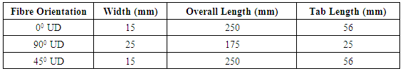
2.1. Tensile Specimen Dimensions
- The tensile specimens were modelled according to the ASTM D 3039/ D 3039M standards. The dimensions are given in the table 1 below.
|
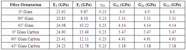
2.2. Material Properties
- The material properties of pure glass laminate and glass carbon hybrid laminate are given in the below table 2.
|
2.3. Modelling in Abaqus CAE
- Figure 1(a) shows the part of zero degree tensile specimen. Figure 1(b) shows adding of the material properties of the zero degree tensile specimens. Figure 1(c) shows the tensile specimen after adding the boundary conditions. Figure 1(d) shows the tensile specimen after meshing.
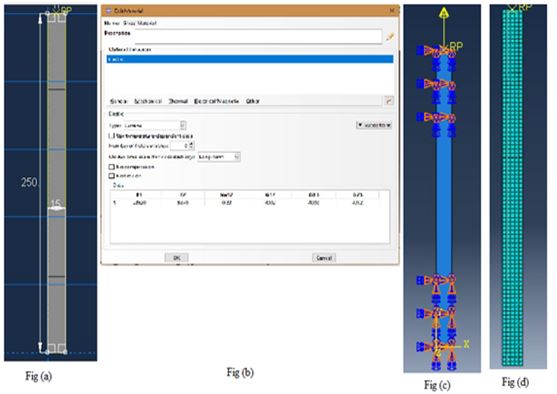 | Figure 1. (a) Creating the part (b) Creating the material (c) Applying boundary conditions (d) Meshing the part |
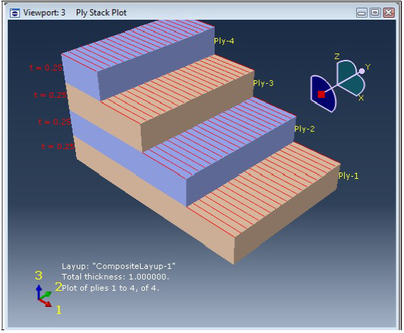 | Figure 2. Composite layup |
|
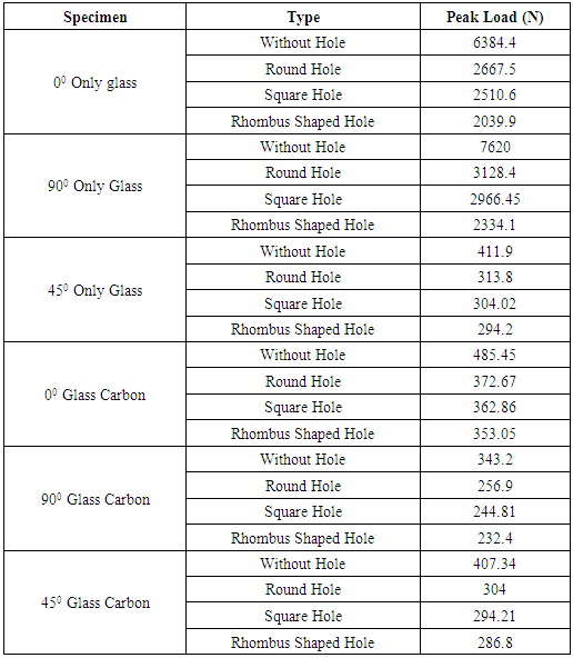
3. Results
- The maximum in-plane principal stresses were obtained from Abaqus for different specimens. Figure 3 shows the maximum in-plane principal stress for zero degree only glass specimen.
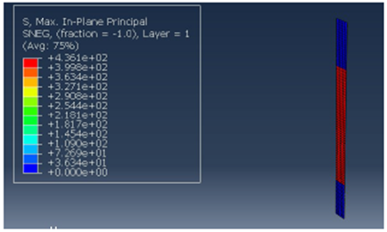 | Figure 3. Maximum in-plane principal stress for 00 only glass specimen |
|
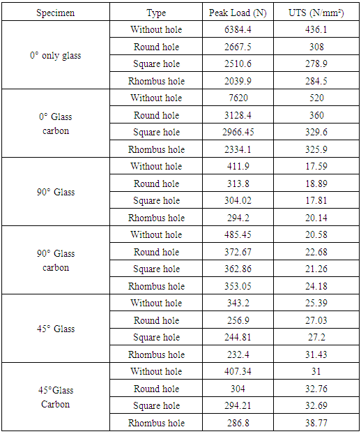
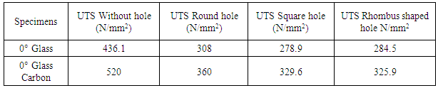
4. Conclusions
- The UTS obtained from the Abaqus is compared in the below table 5 for various tensile specimens.
|
ACKNOWLEDGEMENTS
- Foremost, I would like to express my deepest gratitude to my guide Mr Mahendra M A, Assistant Prof. Department of Aeronautical Engineering, NMIT, Bangalore, for the continuous support to my research, for his patience, motivation, enthusiasm, and immense knowledge. His guidance helped me in all the time of research.Apart from my guide, I would like to thank our PG coordinator Dr. Desai Gowda H S, Prof. Department of Mechanical Engineering, NMIT for his kind support.I am immensely grateful to Dr. P G Mukunda, Prof. Department of Mechanical Engineering, NMIT for sharing his pearls of wisdom with me during the course of this research. I express my sincere gratitude to Dr. Kiran Aithal S, Professor, Department of Mechanical Engineering, NMIT Bangalore, for his support during the course of this research.I am privileged to thank Dr. H.C.Nagaraj, Principal, NMIT, Bangalore, for his support during the course of this project work.Lastly I would like to thank my parents, friends and staff of Mechanical Engineering and Aeronautical Engineering Department of NMIT, Bangalore for their constant support in completing this research.