-
Paper Information
- Next Paper
- Paper Submission
-
Journal Information
- About This Journal
- Editorial Board
- Current Issue
- Archive
- Author Guidelines
- Contact Us
American Journal of Materials Science
p-ISSN: 2162-9382 e-ISSN: 2162-8424
2017; 7(4): 78-82
doi:10.5923/j.materials.20170704.02

Failure Analysis of Woven Glass Fiber Reinforced Epoxy Plastic Composite Laminates by Drilling Using Finite Element Method
 Abstract
 Reference
 Full-Text PDF
 Full-text HTML
Jaimon D. Quadros1, Suhas2, Vaishak N. L.2
1Department of Mechanical Engineering, Birla Institute of Technology, Offshore campus, Ras-Al-Khaimah, UAE
2Department of Mechanical Engineering, Sahyadri College of Engineering & Management, Mangalore, India
Correspondence to: Jaimon D. Quadros, Department of Mechanical Engineering, Birla Institute of Technology, Offshore campus, Ras-Al-Khaimah, UAE.
| Email: |  |
Copyright © 2017 Scientific & Academic Publishing. All Rights Reserved.
This work is licensed under the Creative Commons Attribution International License (CC BY).
http://creativecommons.org/licenses/by/4.0/

The present research work aims at studying the failure of woven glass fiber reinforced epoxy polymer composite laminates by drilling. The drilling experiments are conducted by using three drill bits of different drill point geometries of industrial grade by selecting suitable cutting speed and feed rate values. The drill bits used are made of High Speed Steel (HSS) and Tungsten Carbide materials. The thrust force signals were recorded using a drill tool dynamometer. Stress analysis of the drilled composite laminates based on the thrust force values was conducted in order to predict the design safety by finite element modeling (FEM). Furthermore, failure of the composite laminates is examined theoretically and analytically by using Tsai-Wu failure criterion for predicting ply failure. The results showed that HSS 8 facet drill is not recommended for drilling woven composite laminates as it recorded the highest failure index for high thrust force values. The surfaces of the drilled composites have been examined through SEM micrographs.
Keywords: Drilling, Woven, Finite element modeling, Tsai-Wu failure
Cite this paper: Jaimon D. Quadros, Suhas, Vaishak N. L., Failure Analysis of Woven Glass Fiber Reinforced Epoxy Plastic Composite Laminates by Drilling Using Finite Element Method, American Journal of Materials Science, Vol. 7 No. 4, 2017, pp. 78-82. doi: 10.5923/j.materials.20170704.02.
Article Outline
1. Introduction
- Polymer matrix composites have recently acquired prominence in industry and other engineering applications due to their special characteristics such as high specific strength and specific modulus. The techniques and methodologies involved in processing such composite materials are different from those for metals. Composite manufacturing technology can be classified as primary manufacturing and secondary manufacturing. Standard processes are available for primary manufacturing of composite materials such as molding, pultrusion etc. However, secondary manufacturing requires extensive research input and standardization [1, 2]. Composite design generally necessitates the assembly of sub-components in order to manufacture the final product. The diverse properties of matrix and fibers in combination with fiber orientation play a prominent role in deciding its effect on the drilling process. Thus hole generation becomes an intricate part of component assembly. Drilling operations are basically done in order to contemplate assembly operations. Therefore drilling of composites is crucial for verifying the structural rectitude of the complex composite parts. Delamination has perhaps been recognized as the most fundamental cause for failure of composites during machining. The factors empowering Delamination have been optimized in different ways. Various experimental and theoretical models, optimization procedures have been endorsed for a typical objective of reducing Delamination. Most of the researches on drilling of Composites have focused on minimizing Delamination while prediction of failure stress has comparatively received less attention. Bhatnagar et al. [3] attempted to correlate Delamination with drilling parameters. A major factor that influences Delamination was considered to be tool point geometry. Singh et al. [4] conducted drilling experiments on GFRP on the basis of L27 orthogonal array using 8-facet solid carbide drills. A model based on fuzzy rule was incorporated for predicting thrust force and torque. The results indicated effective use of the model for predicting the outcome based Delamination which could be controlled. Arul et al. [5] studied drilling of glass fiber/epoxy and carbon fiber/epoxy laminates using HSS and tungsten carbide coated drills. The recorded variables were thrust, torque and tool wear. It was concluded that carbide drill gives better performance when compared to HSS drills. Tsao et al. [6] studied the concept of Delamination factor for drilling of carbon fiber-reinforced plastic (CFRP) composite laminates. Effects of drill parameters and drill point geometry on variations observed in cutting force during CFRP composite material drilling were experimentally examined. The results concluded that, Delamination-free drilling process may be obtained by the suitable election of tool geometry and drilling parameters. Based on the literature cited above, the present research work is one such attempt to drill holes by using drill bits of different geometries and materials, on Woven composite laminates of specific dimensions, predict the failure stress based on the Tsai-Wu failure criteria.
2. Experimental Procedure
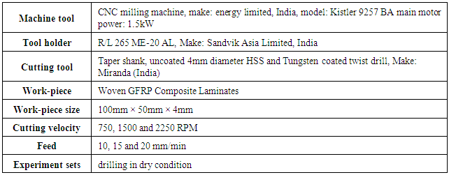
- The primary factors governing composite material drilling are feed rate, speed, tool geometry and material parameters. These factors are recognized to considerably influence Delamination. Woven composites laminates were fabricated by hand lay-up technique. The curing was done at room temperature for 24 hours. The matrix was epoxy L12 and K6 hardener was employed. The specimens were incised to a size of 100*50 mm having 4mm thickness. Holes were drilled in the composite laminates using a CNC milling machine under dry conditions. A drill tool dynamometer was interfaced to a vice on which the specimens were mounted for the recording of thrust force signals. Tungsten carbide and High speed steel (HSS) twist drills of 4mm diameter were used in the experiments. Three types of drills were used-4-Facet, 8-Facet and Jodrill. The drills used were considerably of different geometry and exhibited unconventional behavior under similar drilling conditions. The detailed experimental conditions are as shown in Table 1.
|
3. Experimentation
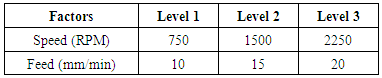
- Experiments were carried out by considering three levels of speed and feed rates. The factors and their levels involved in this study are shown in Table 2. The experiments are conducted using an L9 orthogonal array. An initial run of experiments was conducted for comparative analysis by selecting an appropriate scope of speed and feed rate. The cutting speed was then chosen to be 750, 1500 and 2250 rpm and feed rate was 10, 15 and 20 mm/min respectively. The cutting force i.e. Thrust force (N) which is considered to be the response of the study is recorded using drill tool dynamometer as shown in Figure 1. For each level and factor, a set of three holes were drilled per drill point geometry. Variations in the recorded values were found to be infinitesimal and average values for thrust force responses were considered.
|
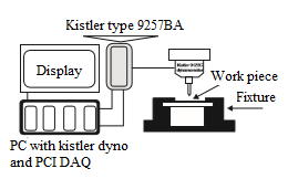 | Figure 1. Experimental Set up |
4. Results and Discussions
4.1. Thrust Force Response
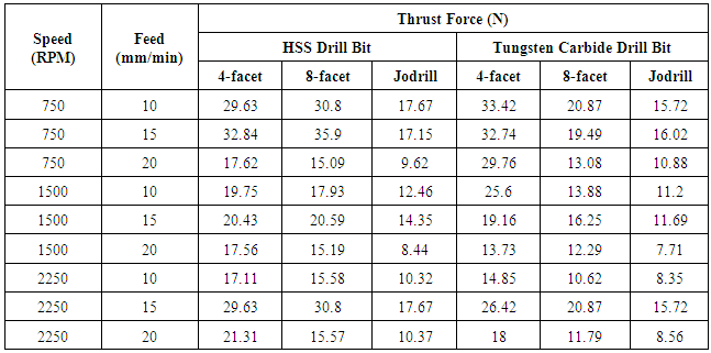
- The Thrust force signals obtained during the drilling process were processed for analysis. In Table 3, it is well noticed that, average thrust force values for jodrill tungsten carbide are found to be minimum when compared to all the drill bits. This is mainly due to the drill point geometry wherein the chisel edge tends to make a mere point contact tending to develop a point contact rather than an edge contact with the composite laminate during the drilling process. Thus, during penetration of the drill into the laminate, there is successive reduction in thrust force. A similar trend is observed in jodrill HSS. However, 8-facet HSS drill produced maximum values of average thrust force owing to constant feed of 15 mm/min and varying speed of 750, 1500 and 2250 RPM. In this case, the High Speed Steel (HSS) tends to cause cumulative Delamination producing a poor surface finish and more number of holes to failure.
|
4.2. Finite Element Modeling
- Experiments are used to study the parametric variations depending on the available responses thereby consume a lot of material and time. Once a model can be validated by using some experimental results, a number of independent parameters can be considered to generalize it. For this purpose, Finite element modeling is one method that is frequently employed. FEM primarily is used to predict stresses, strains and deformations imposed in the material by application of boundary conditions. The present study attempts to model the drilling processes using the FEM approach. The basic focus is to study the influence of thrust force, delivering stresses into the woven composite laminate. The analysis is basically conducted in order to predict the design safety and limit forces to minimize Delamination. The modeling of woven composite laminate drilling is executed as a plate with an inbuilt centric hole at as shown in Figure 2. The drilled hole is simulated as a form of transient drilling action. The present analysis uses shell 181 for modeling the composite material as a 4 noded 3D element with 6 degrees of freedom at each node. The plate is constrained from all four sides so as to minimize the plate bending during application of force. The steps taken for modeling of element include modeling of composite sheet with layers up to 16. A work piece of dimension 10*5 cm with thickness of 4mm has been modeled in ANSYS 13.0 workbench with 0 ̊/90 ̊ oriented layers, 16 in number having density of 2.45 gm/cm3. The model created has taken orientation of fibers into consideration to make the composite laminate.
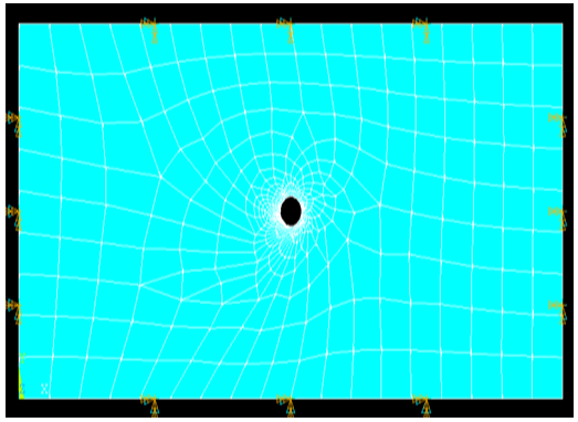 | Figure 2. Inbuilt hole and boundary conditions applied to the specimen |
4.3. Failure Criteria
- To determine laminate failure due to the load applied, the ANSYS program initially estimates stresses across the different plies. When stress is high enough in the first ply or group of plies, it fails. This is the point even beyond which the laminate can still carry the load. However for a safe design, laminates should not experience stress high enough to cause first ply failure. Failure of composites occurs on a micromechanical scale due to fiber breakage, cracking of the matrix, interface or interphone failure etc. The current research work applies Tsai-Wu Failure Criterion for the drill damaged hole. This criterion is used to predict the failure of composites. This failure theory is widely used to predict failure of anisotropic composite materials having similar and varying strengths in tension and compression. On the basis of the information available, a woven composite laminate is developed using general purpose software package, ANSYS, by using the following property data. The stress values in different directions are obtained from analysis through ANSYS. The corresponding tensile, compression and shear properties are taken from Gibson [8]. The properties are as follows:1. Young’s Modulus in longitudinal direction and transverse direction, Exx, Eyy= 21× 103MPa.2. Allowable tensile stress in X, Y direction f1t= f2t= 900×103MPa3. Allowable compressive stress in X, Y direction f1c= f2c= 900×103 MPa4. Poisons ratio ν12=0.28.The combination of stress components are formulated into a functional form for defining failure
 | (1) |
4.4. Critical Thrust Force
- The thrust force has been cited as the primary cause of Delamination [9]. Critical thrust force is a thrust force during drilling at which Delamination initiates failure at different ply locations. The theoretical calculations done by using the Tsai-wu failure criteria predicted the value of critical thrust force Fc= 22.23 N for the range of thrust force values obtained from drilling experiments on Woven composite laminates. Hocheng et al. [10] obtained critical thrust force in graphite epoxy composites by used of an analytical model which was found to be 28N. Tsao et al. [11] used the LEFM approach to predict the critical thrust force for a ply of thickness 5mm and found it to be 26.5 N. At this value of critical thrust force, Tsai-Wu failure index F becomes unity.
 | (2) |
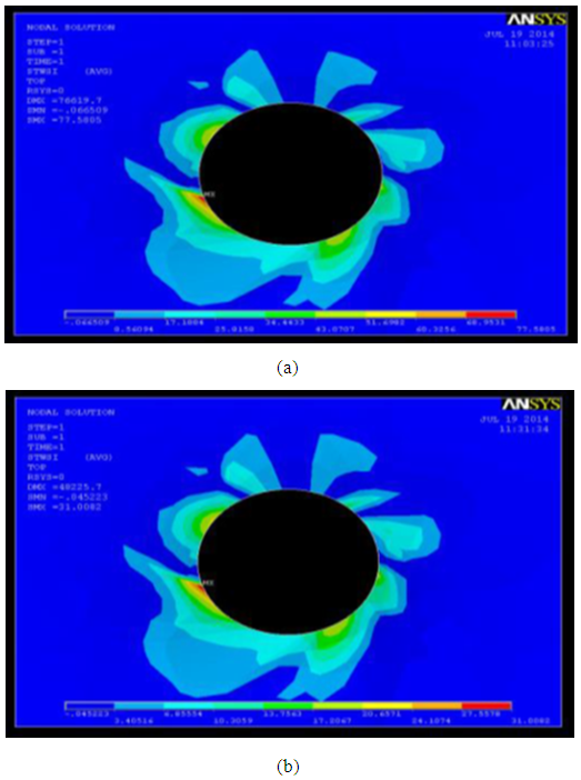 | Figure 3. Tsai -Wu failure stress contour for (a) Critical Tsai-wu failure stress (b) Tungsten carbide 4 facet drill geometry |
|
4.5. Morphology of the Cut Surface
- The SEM micrographs of the drilled hole from HSS 8-facet drill bit and tungsten carbide 8 facet drill bit for specimens are as shown in Figure 4(a, b). It is clearly evident that the hole drilled by 8 facet HSS drill bit of the GFRP specimen has been severely damaged. This is mainly due to fiber pull out causing surface cracks in radial direction. This eventually leads to de-bonding of the matrix and fibers causing severe Delamination [12, 13]. In case of drilling with tungsten carbide drill, the high strength of the composite tends to pull out less amount of fiber at the cutting surface causing lesser number of cracks thereby. Also the crack formation in GFRP is difficult to propagate in the plane of lamina to meet together, thereby resulting in lesser Delamination.
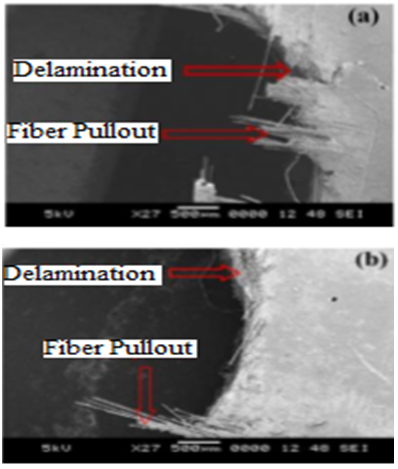 | Figure 4. SEM micrographs showing surface morphology of the drilled hole a) HSS 8-facet drill bit and b) tungsten carbide 8-facet drill |
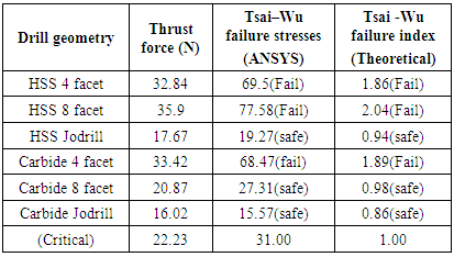
5. Conclusions
- The objective of the present work is to predict failure of woven composite laminate by drilling with 4 facet, 8 facet and jodrill bit geometries. The experiments are carried out in order to study the effect of cutting forces such as thrust force on failure. The main findings include:Ÿ HSS 8 facet drill is not recommended for drilling Woven composite laminates as it recorded the highest failure index for high thrust force values. Ÿ Tsai-wu failure stresses for HSS 4 facet, HSS 8 facet, and carbide 4 facets drills are detected to be more than critical Tsai –wu failure stresses obtained from analysis thereby eliminating the use of these drill bits for drilling of Woven composite laminates. However, Tsai-wu failure stresses for HSS jodrill, 8- facet tungsten carbide, and tungsten carbide jodrill are comparatively lesser than critical Tsai-wu failure stresses hence recommended for drilling Woven composite composites.Ÿ The SEM analysis evidenced that, the hole drilled of the GFRP specimen was severely damaged mainly due to fiber pull out causing surface cracks in radial direction. This eventually led to de-bonding of the matrix and fibers causing severe Delamination.