-
Paper Information
- Next Paper
- Paper Submission
-
Journal Information
- About This Journal
- Editorial Board
- Current Issue
- Archive
- Author Guidelines
- Contact Us
American Journal of Materials Science
p-ISSN: 2162-9382 e-ISSN: 2162-8424
2016; 6(5): 125-134
doi:10.5923/j.materials.20160605.02

Mechanical and Thermal Properties of Graphene Nanoplates and Functionalized Carbon-Nanotubes Hybrid Epoxy Nanocomposites
 Abstract
 Reference
 Full-Text PDF
 Full-text HTML
Ahmed A. Moosa1, Faris Kubba1, Maysam Raad1, Ahmad Ramazani S. A.2
1Department of Materials Eng. Technology, Engineering Technical College, Middle Technical University Baghdad, Iraq
2Department of Chemical and Petroleum Engineering, Sharif University of Technology, Tehran, Iran
Correspondence to: Ahmed A. Moosa, Department of Materials Eng. Technology, Engineering Technical College, Middle Technical University Baghdad, Iraq.
| Email: |  |
Copyright © 2016 Scientific & Academic Publishing. All Rights Reserved.
This work is licensed under the Creative Commons Attribution International License (CC BY).
http://creativecommons.org/licenses/by/4.0/

The effect of dispersion of carbon nanofillers on mechanical properties, wettabiliy and thermal stability of epoxy nanocomposites prepared by direct mixing method were studied. Field Emission Scanning Electron Microscopy (FESEM) was used to study dispersion of carbon nanofiller in epoxy matrix. The tensile properties of the prepared Epoxy/GNPs nanocomposites by direct mixing method using (0, 0.1, 0.25, 0.5, 0.75 and 1 wt %) GNPs showed significant improvement (ca. 59% and 62%) in the ultimate tensile strength and Young's modulus of nanocomposites respectively at a loading of 0.5 wt % GNPs. At loading higher than 0.5%, the mechanical properties start to decrease but still higher than that of neat epoxy due to agglomeration of GNPs. The Epoxy/ GNPs-FMWNTs nanocomposites was prepared using 0.5 wt % GNPs:FMWNTs nanofiller with different GNPs:CNTs mixing ratio (1:9, 2.5:7.5, 5:5, 7.5:2.5, and 9:1). The best improvements in mechanical properties was found at two mixing ratios of GNPs: FMWNTs (5:5) and (9:1). Water absorption of neat epoxy was 0.56% and decreases to 0.48% by adding 1 wt % of GNPs, and decrease to 0.49% by adding 0.5 wt. % FMWNTs. The contact angle of neat epoxy was 43.5°. The hydrophilic of epoxy resin decreases by adding 1 wt % GNPs where contact angle is 67.5°.
Keywords: Hybrid nanocomposites, Multi-walled carbon nanotubes, Graphene, Epoxy, Tensile Strength
Cite this paper: Ahmed A. Moosa, Faris Kubba, Maysam Raad, Ahmad Ramazani S. A., Mechanical and Thermal Properties of Graphene Nanoplates and Functionalized Carbon-Nanotubes Hybrid Epoxy Nanocomposites, American Journal of Materials Science, Vol. 6 No. 5, 2016, pp. 125-134. doi: 10.5923/j.materials.20160605.02.
Article Outline
1. Introduction
- Graphene is a single layer of carbon atoms forming a two dimensional (2D) honeycomb lattice. In principle, Graphene is considered as the building block for all sp2–hybridized carbon allotropes such as fullerenes and CNTs [1]. Graphene nanoplates (GNPs) are the thinnest material discovered in the universe till now and the strongest materials ever measured [2]. Owing to its unique electrical, thermal, and mechanical properties, graphene has attracted great attention in many applications. Single layer graphene has high thermal conductivity 5000 W/mK [3] which is higher than the thermal conductivity of other carbon allotropes. Graphene has high electrical conductivity up to 6,000 S/cm [4] and excellent mechanical properties with Young’s modulus of 1 TPa and ultimate strength of 130 GPa [5]. Thus, graphene is a promising material for high-performance nanoelectronics, heat dissipation, sensors, field emission and transparent conductor [6]. CNTs are tubular 1D structure, have nanometer scale diameter and micrometer scale length. CNTs attracted the attention of many researchers since their discovery in 1991 by Iijima [7] until now because of their electronic, mechanical, and thermal properties as well as their good chemical stability and adsorptive properties [8]. The development of CNT reinforced polymer nanocomposites has been impeded by the agglomeration of CNTs due to their large aspect ratio and VanderWaals forces. This leads to the dispersion difficultly in polymer matrix [9].The potential applications of CNTs/polymer and GNPs/polymer nanocomposites are limited because of the aggregation of CNTs due to their size and large aspect ratio and the restacking of GNPs to form graphite due to their strong
 interaction and large van der Waals (Yang et al.) [10]. The major challenge is to successfully achieving homogeneous dispersion of CNTs and GNPs in the polymer matrix. Hybrid nanocomposites have attracted the attention of many researchers by using two or three nanofillers e.g. MWCNT with graphene platelets or with other nanomaterials (CNTs, inorganic nanowires and nanoparticles) [10]. MWCNTs can bridge adjacent GNPs and prevent their restacking, resulting in an increased contact surface area between GNPs/ CNTs structures [11, 12]. This improve the mechanical properties and thermal conductivity of GNPs-CNTs/ epoxy hybrid nanocomposites. Zhang et al., [13] showed significant improvement of the tensile strength and Young’s modulus of the PVA/GNPs-MWNT hybrids nancomposites with 0.6 wt% GNPs -CNTs. This is due to the homogeneous dispersion and synergistic interaction of the two kinds of nanofillers.Yue et al., [14] used ultrasonication method to disperse CNT-GNPs hybrid nanofillers into an epoxy matrix at different mixing ratios of CNT: GNP. A remarkable improvement in the mechanical properties and electrical conductivity of epoxy nanocomposites prepared by shear mixing followed by sonication and reinforced with (0.1, 0.2, 0.3, 0.4) wt% functionalized Multiwalled Carbon Nanotubes (FMWCNTs) as reported by Moosa et al., [15].
 2. Experimental Work
2.1. Materials
- Graphene Nanoplates with 97% purity consist of 4-5 graphene layers with an average thickness of 2 nm and an average diameter of 1 microns was purchased from XG Science Company, Lansing, MI, USA. Functionalized Multiwalled Carbon Nanotubes (FMWCNT) with
 in length and < 8nm in diameter are obtained from Neutrino Nanovation, TECNAN company, China. The epoxy material and the hardener were purchased from (Mokarrar Engineering Materials Co., Iran). The epoxy resin (Epikote 828) (density = 1.16 g/cm3, viscosity = 110-150 Poise). The hardener used is Aliphatic Amines produced from triethylenetetramine (TETA) with a commercial name EPI-CURE curing agent 3234. The epoxy to hardener mixing ratio is 100:15.
 2.2. Preparation of Nanocomposites
- The experimental work was done at Sharif University of Technology, Tehran, Iran. The epoxy/GNPs nanocomposite were prepared by direct mixing of (0.1, 0.25, 0.5, 0.75 and 1 wt%) graphene nanoplates (GNPs) with epoxy. The GNPs and the epoxy resin were weighted using digital balance. The epoxy/GNPs mixture was first mixed with mechanical mixer (Griffin & George Limited, Great Britain) at 1500 (rpm) for 15 min to achieve macro dispersion of GNPs in epoxy. This was followed by high shear mixer (Ultra-Turrax, T18 Germany) at 12300 (rpm) for 30 min in an ice-water bath to prevent excessive heating which caused by high shear forces. Micro-dispersion of GNPs into an epoxy resin was done using ultrasonication probe (UP400S, Germany) for 30 min at 144W power, 24 kHz frequency in an ice-water bath to prevent excessive heating generation during ultrasonication process. The hardener was then added into epoxy/GNPs with a ratio 100:15 wt. % (resin: hardener) and mixed thoroughly by hand using glass rod. Then, the mixture was degassed for 2 minutes to remove the bubble using centrifuge (EB series, Centurion Scientific, UK) at speed of 1500 rpm and then cast in a silicon rubber mold (ASTM D-638 type I). After casting of nanocomposite samples, the filled silicon molds were left at room temperature for 24 hours for curing process. The samples were then removed from the mold and heated in an oven at 80°C for 3 hours for post-cured. A neat epoxy reference sample was also prepared by the same procedures. The Epoxy/ GNPs+FMWNTs hybrid nanocomposite sample was prepared by the similar procedures that were used to prepare Epoxy/GNPs nanocomposite. The epoxy resin was mixed with 0.5wt.% (GNPs+FMWNTs) using different (GNPs:FMWNTs) ratio as (0:10, 1:9, 2.5:7.5, 5:5, 7.5:2.5 and 9:1).
2.3. Characterization and Instruments
- The Field Emission Scanning Electron Microscope (FESEM) with spatial resolution down to 1.5 nm (Mira 3 Tescan FESEM, Czech) was used for characterization of the MWCNTs, GNP and the morphology of fractured surface of tensile sample of the epoxy nanocomposites. The tensile test specimens were tested using Universal testing machine (HIWA 200, Korea) at maximum load.The tensile properties tests were performed based on the ASTM procedure by an Universal Testing Machine (HIWA 200, model 2125, HIWA Engineering Co., Korea) at maximum Load 5000 Kgf, with maximum speed 500 mm/min. The thermogravimetric analysis (TGA) was used to evaluate the thermal stability of all the fabricated nanocomposite samples as a function of the temperature using TGA/DSC 1 (METLER TOLEDO Compony, USA). The heating rate is 10°C /min under nitrogen gas flow rate 40 ml/min from room temperature to 700°C. The contact angles of the liquid drop on the surface of the nanocomposite samples were measured using a portable optical microscope with software Image J.
3. Results and Discussion
3.1. Tensile Properties of Epoxy/GNPs Nanocomposites
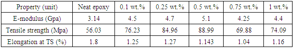
- The mechanical properties of Epoxy/GNPs nanocomposites with GNPs (0.1, 0.25, 0.5, 0.75, 1 wt%) are shown in Table 1. The addition of GNPs to epoxy increases the tensile strength up to 0.5wt% GNPs where the maximum tensile strength occurs. The ultimate tensile strength increases from 56.03 MPa for neat epoxy to 88.99 MPa for the epoxy nanocomposite containing 0.5 wt % GNPs. The tensile strength of the pure epoxy is 56.03 MPa and the tensile strength for nanocomposites with 0.1 wt. % GNPs is 76.23 MPa which is an increment of 36.05%. The tensile strength increments are 52%, 59 %, 25% and 32% at 0.25, 0.5, 0.75 and 1 wt% GNPs loadings, respectively. At 0.75 and 1 wt% GNPs the tensile strength starts decreasing. The tensile strength of epoxy/GNPs is higher than that of neat epoxy. The Young’s modulus of the epoxy/GNPs nanocomposites increases with increasing GNPs wt%. The maximum Young’s modulus of the epoxy/GNPs nanocomposites occurs at 0.5 wt% GNPs, Table 1. The Young’s modulus of pure epoxy is 3.14 GPa, and the Young’s modulus for nanocomposites with 0.1 wt. % GNPs is 4.50 GPa, which is an increment of 43%. The tensile modulus also shows 50%, 62%, 35% and 40% increments at 0.25, 0.5, 0.75 and 1wt % GNPs loading, respectively. At 0.75 and 1 wt% GNPs the Young’s modulus start decreasing but still higher than that of neat epoxy.
|
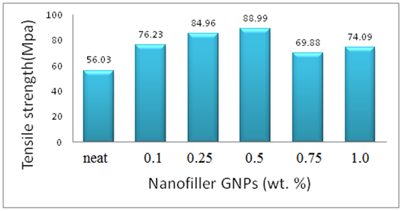 | Figure 1. Tensile strength of Epoxy/GNPs nanocomposites |
3.2. Tensile Properties of Epoxy/GNPs-FMWNTs Nanocomposites
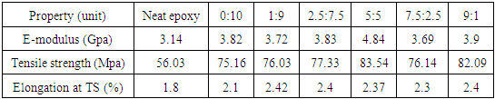
- The mechanical properties of Epoxy/GNPs-FMWNTs nanocomposites containing fixed weight fraction of GNPs / FMWNTs hybrids (0.5wt %) with different mixing ratio of GNPs:FMWNTs (0:10, 1:9, 2.5:7.5, 5:5, 7.5:2.5 and 9:1) are shown in Table 2. The ultimate tensile strength increases from 56.03 MPa for neat epoxy to 83.54 MPa for the epoxy nanocomposite containing 0.5 wt % GNPs -FMWNTs with mixing ratio GNPs:FMWNTs(5:5). The maximum tensile strength occurs at GNPs:FMWNTs 5:5 with an increment of 49%.
|
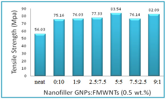 | Figure 2. Tensile strength of Epoxy/GNPs-FMWNTs nanocomposites |
3.3. Fracture Surface of Epoxy/GNPs Nanocomposite
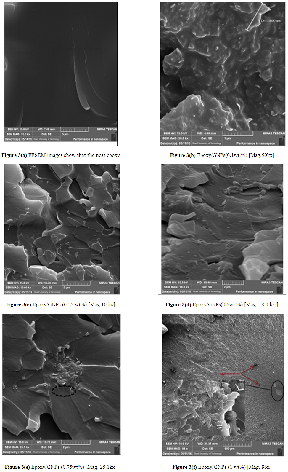
- FESEM images show that the neat epoxy, Figure 3(a). FESEM images of the fracture surface of Epoxy/GNPs nanocomposite specimens show a homogenous dispersion of GNPs with epoxy matrix, Figures 3 (b) (c) and (d) and this improves the mechanical properties and also enhancing the fracture toughness. The fracture surface morphology of Epoxy/GNPs nanocomposite specimens have rough surface produce from changing the crack propagation direction (i.e., the crack deviated from its original plane). Graphene nanoplates act as an obstacle for crack propagation. These obstacles provide the fracture surface micro ruptures with different size depending on weight fraction and dispersion of GNPs in epoxy. These micro- ruptures can arrest crack growth by releasing the stress and lead to improvement of mechanical properties. The increasing of wt% of GNPs will reduce the distance between graphene nanoplates which reduce the size of micro ruptures on the fracture surface. The Epoxy/0.5wt.% GNPs nanocomposite gives better dispersion with no agglomeration and this gives better increase in mechanical properties compared with (0.1, 0.25, 0.75 and 1) wt. % as shown in Figure 1.For epoxy with GNPs greater than 0.5 wt%, Figure 3 (e) and (f), agglomeration occurs and these agglomerates act as stress concentration sites due to smaller distance between GNPs as well as present strong van der waals forces and π-π interactions between GNPS, lead to restack GNPs and forming aggregates. At the same time, the aggregated GNPs would act and obstacles which restricting matrix flow and resulting in the formation of micro voids and micro holes between GNP and epoxy [10].
 | Figure 3. FESEM image of the fracture surface of Epoxy/GNPs |
3.4. FESEM of Fracture Surface of Epoxy/GNPs-FMWNTs Hybrid Nanocomposite
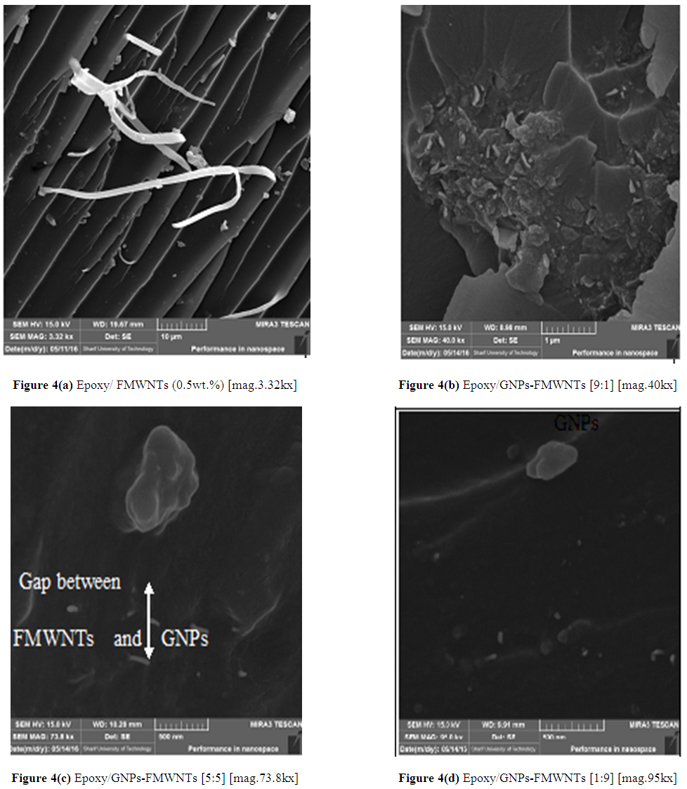
- Figure 4 (a) shows FESEM images of tensile fracture surface of Epoxy/ 0.5wt% FMWNTs nanocomposite with better dispersion due to the functional group (Carboxyl group). These functional groups lead to overcome the van der walls attraction forces between MWNTs by electrostatic/steric repulsive forces and increase interfacial bonding between MWNT and epoxy. In Epoxy/CNT nanocomposites, crack bridging mechanisms play important role in improving fracture toughness of nanocomposite samples. Large energy was dissipated within bridging mechanisms due to very small diameter in nanoscale and large length in microscale of nanotubes and crack deviation may take secondary role [21]. When nanotubes bridge two fracture surfaces, it may either fracture or pulling out from one of the surfaces and appear to lie on the fracture surface depending on the flexibility of the Epoxy - nanotubes interfacial strength, embedded length and angle to fracture surface of nanocomposite [22]. From the degree of pulling, one can suggest the weak interfacial bonding between epoxy- nanofiller. In Epoxy/ 0.5wt% GNPs Figure 3d, no GNPs appeared (no pullout) on fracture surface and this indicates strong interface interaction. For Epoxy/ 0.5wt% FMWNTs, Figure 4a, little pullout appeared on the fracture surface and this indicates that interface interaction was strong due to carboxyl group on the surface of functionalized MWNTs. These functional groups give a strong interfacial bonding between FMWNT and epoxy and more compatible than nonfunctionalized MWNTs. As a result, CNTs show lower enhancement in mechanical properties compared with the graphene nanoplates.Figure 4 (b) (c) and (d) show the FESEM images of hybrid nanocomposites containing fixed wt% (0.5 wt. %) of GNPs:FMWNTs with mixing ratio of [9:1], [5:5] and [1;9], respectively. The images show good dispersion of nanofillers. In general, surface functionalization of MWNTs enhances adhesion and compatibility between MWNTs and the Epoxy matrix due to functional groups. For the Epoxy/GNPs-FMWNTs images with mixing ratio [9:1], Figure 4(b), both of the GNPs and FMWNTs are embedded in the matrix, which will improve the mechanical properties of the composites compared with the Epoxy/GNPs-FMWNTs at mixing ratio of GNPs:FMWNTs [1:9] as in Figure 4 (d).
 | Figure 4. FESEM images of GNPs:FMWNTs hybrids nanocomposites containing fixed weight fraction (0.5 wt. %) with different mixing ratios |
3.5. Thermogravimetric Analysis (TGA)
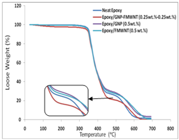
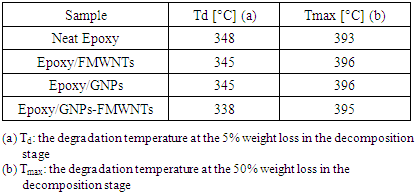
- The thermal behavior curves, Figure 5, of nanocomposite specimens can be divided into three stages: initial decomposition, Tg curve, and complete decomposition. All specimens show very small initial decomposition, Figure 5 for each of neat epoxy, Epoxy/GNPs, Epoxy/FMWNTs, and hybrid Epoxy/GNPs-FMWNTs which may be caused by the loss of volatiles. The hybrid Epoxy/GNPs-FMWNTs exhibit a little more initial decomposition. The onset temperature of decomposition (Td) can be considered as the temperature at the 5% weight loss. The relative thermal stability of the samples is evaluated by Td and (Tmax).
 | Figure 5. TGA of neat epoxy and its nanocomposites |
|
3.6. Differential Thermogravimetry (DTG)
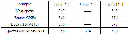
- Differential thermogravimetry (DTG) (1st derivative) was used to determine the peak degradation temperature of (Neat epoxy, Epoxy/GNPs, Epoxy/FMWNTs and Epoxy/GNPs-FMWNTs) with loading amount 0.5 wt.% of nanofillers. The degradation temperatures (TDTG) of nanocomposite specimens are shown in Table 4 and Figure 6. The TDTG1 (370± 3°C) value was not affected by the addition of the FMWNTs nanofillers. For Epoxy/GNPs, and Epoxy/GNPs-FMWNTs the TDTG1 (360 ± 4°C) value was not affected by the addition of nanofillers but it is 10°C lower than that for Epoxy/FMWNT. This may be caused by the presence of Graphene.
|
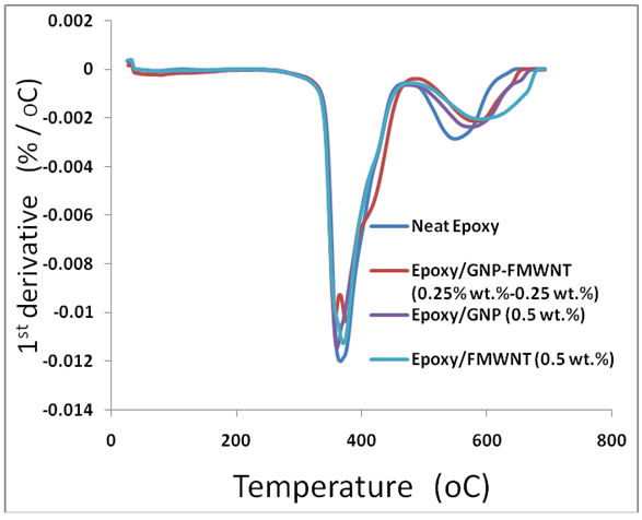 | Figure 6. DTG thermograms for neat epoxy and its nanocomposites with enlarge section of Epoxy/GNPs-FMWNTs samples |
4. Contact Angle of Nanocomposite
- The static contact angles of the water drop were measured over the surfaces of neat epoxy, Epoxy/GNPs, Epoxy/FMWNT, and Epoxy/GNPs-FMWNTs hybrid nanocomposite samples using optical microscope.
4.1. Contact Angle of Epoxy/GNPs Nanocomposite
- Figure 7 shows contact angle for Epoxy/GNPs. For neat epoxy the contact angle is 43.5° which is hydrophilic. For GNPs/epoxy composite the contact angle is higher than that for neat epoxy. The range of contact angle for GNPs/epoxy composite is between (43.5-67.5°) corresponding to GNPs range 0 - 1 wt%. The maximum contact angle is 67.5° at 1 wt% GNPs is and the GNPs/epoxy composite is a hydrophilic material.
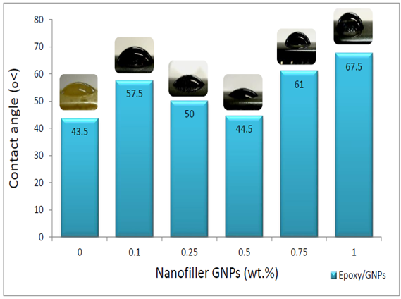 | Figure 7. Contact angle for Epoxy/GNPs Nanocomposites |
4.2. Contact Angle of Epoxy/GNPs-FMWNTs Nanocomposite
- Figure 8 shows contact angle for Epoxy/GNPs-FMWNTs. For neat epoxy the contact angle is 43.5° which is hydrophilic. For different ratios of GNPs: FMWNTs the contact angles are higher than that for neat epoxy. The range of contact angle for Epoxy/GNPs-FMWNTs nanocomposite is between (55.5- 62.5°) corresponding to GNPs: FMWNTs ratio ranges 0:10 – 9:1.
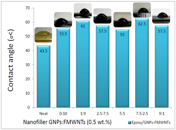 | Figure 8. Contact angle for Epoxy/GNPs-FMWNTs Nanocomposites |
5. Water Absorption of Nanocomposite
5.1. Water Absorption of Epoxy/GNPs
- Figure 9 shows the water absorption percentage of neat epoxy and Epoxy/GNPs nanocomposite samples. For neat epoxy the water absorption percentage is 0.56%. With the addition of 0.1 wt.% of GNPs to epoxy the water absorption percentage decreased to 0.52% because of the hydrophobicity of GNPs [26] and barrier properties of GNPs nanofiller [32, 33]. The creation of tortuous pathway for H2O molecules to diffuse inside the nanocomposite when using nanofiller with high aspect ratio on epoxy [33]. Thus, with increasing wt% of GNPs, these process opposes the influence of hydrophobic and barrier properties of GNPs and reduce it. So, with increase GNPs the water absorption percentage increases in the range (0.52%-0.55%) corresponding to GNPs range 0.1- 0.5 wt. % but still in range less than neat epoxy. The addition of more GNPs will lead to agglomerate and this reduce the interface pathway for H2O which reduce the water absorption percentage in range (0.55%-0.48%) for GNPs range 0.5- 1 wt.%.
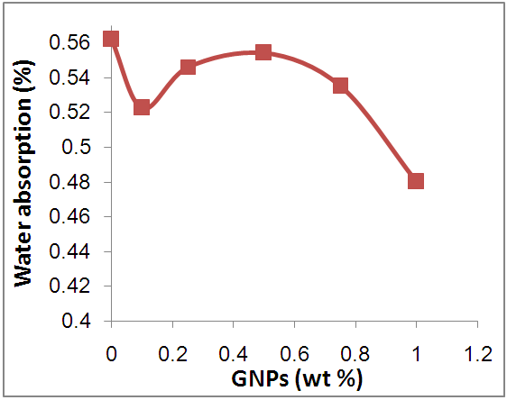 | Figure 9. Water absorption vs. nano-filler GNPs |
5.2. Water Absorption of Epoxy/GNP-FMWNT Nanocomposite
- Figure 10 shows the water absorption percentage of Epoxy/GNPs-FMWNTs hybrid nanocomposite samples with fixed nanofiller weight fraction (0.5 wt.%) and different mixing ratio. The water absorbency of Epoxy/ GNP-FMWNNT nanocomposite is affected by functional groups attached to the surface of CNTs.
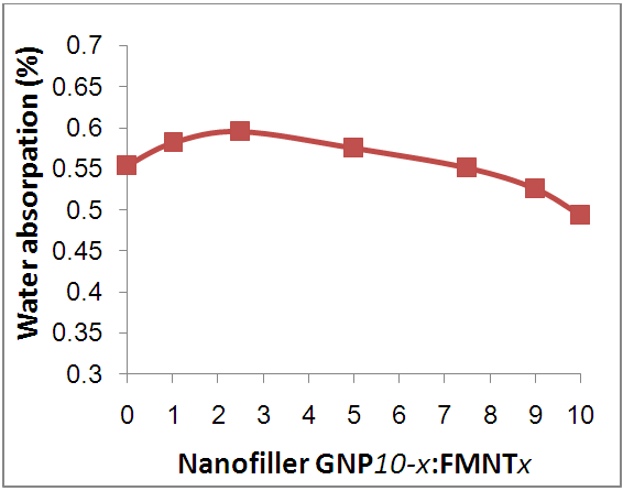 | Figure 10. Water absorption vs.GNPs-FMWNTs nano-fillers with fixed weight fraction (0.5 wt.%) at different mixing ratio |
6. Conclusions
- In this work, epoxy/GNPs and Epoxy/GNPs-FMWCNTs nanocomposites were prepared by direct mixing method. Good improvement in dispersion and stability of nanofillers in epoxy was obtained using "Direct Mixing" method (mechanical mixing and high shear mixing followed by sonication. This method is low cost, environmental friendly and fast. The best GNPs loading was at 0.5 wt% for epoxy/GNPs nanocomposites where both of ultimate tensile strength and Young's modulus of epoxy/GNPs were mechanical mixing and high shear mixing followed by sonication was used. This method is low cost, environmental friendly and fast. The best GNPs loading was at 0.5 wt% for epoxy/GNPs nanocomposites where both of ultimate tensile strength and Young's modulus of epoxy/GNPs were enhanced. For epoxy/ 1wt% GNPs nanocomposites, the contact angle changed from 43.5° for epoxy to 67.5°, and water absorption decreased from 0.56% to 0.48%. Thermogravimetric analysis results for neat epoxy, Epoxy/GNPs, Epoxy/FMWNTs, and Epoxy/GNPs-FMWNTs do not show any major influence on thermal stability of epoxy.The best improvements in Young’s modulus of prepared Epoxy/ GNPs-FMWNTs hybrid nanocomposite using 0.5 wt % GNPs:CNTs nanofiller with different GNPs:CNTs mixing ratio was found at two mixing ratios of GNPs: CNTs (5:5) and (9:1). The Young’s modulus of the Epoxy/GNPs-FMWNTs with mixing ratio (5:5) was 54% greater than the neat epoxy. This may be related to enhance nanofiller/matrix interface by functional group. The ultimate tensile strength of the Epoxy/GNPs-FMWNTs with mixing ratio (5:5) was 49% greater than the neat epoxy.