José Ernesto Tonon1, João Roberto Sartori Moreno2, Julio Cesar Sousa Francisco2, Marcelo Luiz de Freitas Fogal3
1Faculdade de Engenharia de Marilia, UNIMAR, Marília, São Paulo, Brazil
2Programa de Pós-graduação em Engenharia Mecânica, Universidade Tecnológica Federal do Paraná, Av. Alberto Carazzai, Cornélio Procópio, Paraná, Brazil
3Jacto Research Center and Development, Paulópolis, São Paulo, Brazil
Correspondence to: João Roberto Sartori Moreno, Programa de Pós-graduação em Engenharia Mecânica, Universidade Tecnológica Federal do Paraná, Av. Alberto Carazzai, Cornélio Procópio, Paraná, Brazil.
| Email: |  |
Copyright © 2015 Scientific & Academic Publishing. All Rights Reserved.
Abstract
This study was based on the combination of simple and quick techniques to substitute the conventional manufacturing system assembly of metal truss connected by wood structures for free environments and less movement. Although simple in its use, the bolted connections are extremely complex in their analysis and behavior. The study was based on evaluating bolted wood/wood and wood/wood with a metal divider interface connections, just to observe the strength of the set's performance under real loads of support coming from the roof elements of the work. Load tests to evaluate the shear behavior nonlinear of the connecting bolts were carried out with loads until 10 ton. On prototypes previously dimensioned according to NBR 6120 to determination of the values of the loads, with two, three and four bolts of the type SAE J 429 grade 5. It was observed that the insertion of a metal plate between the pieces of wood increased by about 50% in the shear strength of the connection. The models A1 and B1, with two bolts with or without plate, were the ones with least resistance, while with three bolts were most loads resisted. Simulations with FEMAP-Finite Element Modeling and Post-processing/NASTRAN were performed for comparison.
Keywords:
Bolted connections, Nonlinear, Strain levels, FEMAP/NASTRAN
Cite this paper: José Ernesto Tonon, João Roberto Sartori Moreno, Julio Cesar Sousa Francisco, Marcelo Luiz de Freitas Fogal, Evaluation of Shear Resistance of Bolted Connections in Wood/Wood and Wood/Steel Plate/Wood, American Journal of Materials Science, Vol. 5 No. 2, 2015, pp. 47-52. doi: 10.5923/j.materials.20150502.04.
1. Introduction
Wood is used in many structural applications around the world due to its economy, its good strength to weight ratio, and its status as a renewable resource. This widespread use demands a comprehensive understanding of the material properties and the mechanical behaviors of wood and wood connections. The connections, in particular, are vital to the safety and stability of wood structures with and without steel plate as in [1], as they distribute load between structural members, and provide ductility within the system. The integrity of a structure under load depends on the structural members and the connections. Bolts massive are one of the most important and common connectors and are used to attach wood members together in a variety of ways according to [2]. Appropriate connections are important for the structural performance and maintenance of a wood structure attached with bolts, although most concern is the direction perpendicular stresses of action of the loads.The various grades of structural steel bolts are based on mechanical properties such as strength, hardness, and ductility. These mechanical properties are dependent on the presence and percentage of different elements in the steel alloy, and on the processes used to form and treat the bolts. Accurate analysis of the connection is difficult due to the number of connection components and their non-linear behavior. The bolts, welds, beam and column sections, connection geometry and the end plate itself can all have a significant effect on connection performance.The deformations due to the action of loads, implies the failure in shear, which can generally occur in wood bolted connections as shown in (Figure 1).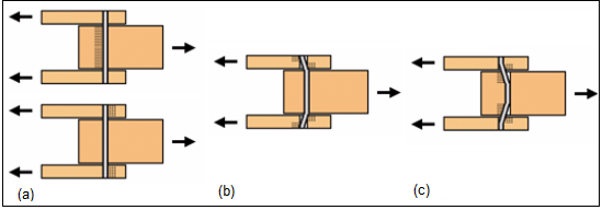 | Figure 1. Three members (double shear) bolts joint failures modes |
According to [3] the structural support function of a wood structure is to receive and transfer the loads of the plot for construction of distributive mode, which depends on the choice of an appropriate profile of the form loading as shown the diagram in (Figure 2).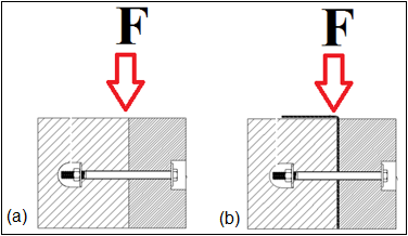 | Figure 2. Effort acting on the connection, (a) wood/wood and (b) wood/steel plate/wood |
The main feature of the structure in the system is besides connecting elements which are the sums of the diagonals, the action of the flanges that must be connected in different planes to support the overloads.The objective of this study is to evaluate the set of wood/wood connected by bolts when subjected to shear forces, and compare with similar connections, but using a metal plate pressed between parts of wood.
2. Experimental Procedure
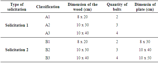
In this study the bolts and plate, will be embedded in the wood, so they are not shown. For further analysis of each material and assembly, three models were created and divided into two requests. In one application, the connection is performed with flat bolts, washers and nuts, whereas the second request, besides bolts, there will be cold folded thin plate and pressed between the pieces of wood.The identifications of the variables are presented in Table 1 and we highlight on requests and classifications as the dimensions of the beams and plates and quantities of bolts.Table 1. Classification of Variables
 |
| |
|
The first solicitation is classified as A1, A2 and A3, and has as templates varying the pieces of wood of the dimensions and quantities of bolts, while solicitation 2 is classified as B1, B2 and B3, which apart from the variations of dimensions and the quantities of the bolts varies the size of the sheet pressed between them.Compression tests were performed on wood/wood and wood/plate/wood supported on supports constructed of the same wood pieces set exactly to inhibit the movement of the model and this could rotate when applying the load. The mounting kit provided immobility of parts and guaranteed reliability of the results that would compare with the simulation by FEMAP.The tests were carried in connections as can be seen in (Figure 3) where the loads was always between 4000 and 10000 Kgf applied by the device speed 5 mm/min. 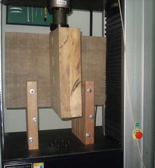 | Figure 3. Description of device and set to be tested |
The program FEMAP - Finite Element Modeling and Post-processing/NASTRAN generated a tension ratio of each element of the connection, which can be used to measure the resistance of the wood pieces, bolts and plates from a load stipulated. Such simulation is based and justified by the finite element analysis of bolted end-plate beam connections as related for [4].
3. Results and Discussion
The experiments were performed by following the references A1, B1; A2, B2; A3 and B3, and models without plates supported almost half the load, compared to those who had included the plate pressed between parts.Models A1 and B1, with two bolts were that received load to the total destruction of the wood. A2 and B2, with three bolts, revealed a fissure in the same location as the crosspiece of the two bolts, and A3 and B3 with four bolts did not show any crack in any of the pieces of wood.As show at (Figure 4) have a sequence of application of the load and the model behavior more precisely positioned transversally the set.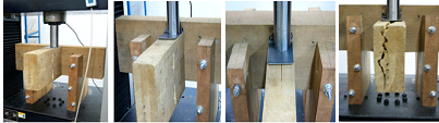 | Figure 4. Sequence of application of the load in the sets and models with and without plate |
It was noted that due to loads, the first material suffer from the wood which was load modulus of elasticity (18500 MPa) is approximately ten times lower than that of steel. This reflected precisely in the fact that the bolt nearest the load is applied to the shear compressive effects it deforms less than the farthest connectors location of load application.The first failure that occurred during the compression tests was plug shear followed by slight crack development and wood embedment failure. Also, the cracks started to open up and beam failure (e.g. bending failure and compression failure) started to occur. Examination of the tested specimens showed no visual bolt yielding had taken place at the joist member; however, the bolts of the column member were slightly bent according to [5].Table 2 present data of comparison between the connectors in wood/wood (A1, A2, A3) and wood/plate/wood (B1, B2, B3) models. The model with two bolts was considered as the base line (base reference) and factors for each piece is proportional to how much you can increase the load relative to the base line. It can be observed from the results that a significant improvement when added to plate even not increasing the number of bolts. It can be said that the model with 3 bolts and plate supports more load than the model without plate using 4 bolts.Table 2. Comparison between the connectors in wood/wood and wood/plate/wood models
 |
| |
|
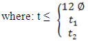
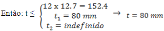
Calculations loads for two, three and four boltsThe calculation of the maximum strength bolted connection using flat bolts diameter of 12.7 mm with washers and nuts.Consider:A1 - Model in dimension 8.0 x 20 cm with two bolts;A2 - Model in dimension 10.0 cm x 30.0 cm with three bolts;A3 - Model in dimension 10.0 cm x 40.0 cm with four bolts.Determination of Kmod:.Datas: Loading long term: Kmod,1 = 0.7;Class of humidity 1 and 2: Kmod,2 = 1.0;Wood: Kmod,3 = 0.8
 Determination of the design strength:
 Determining the strength of wood in compression perpendicular the fibers:
 Calculation of the value of
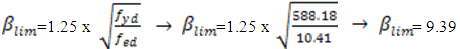 where:
 As ASTM A-325 the yield stress of the steel is 64.7kgf/mm² A1 - Determination of maximum strength on the connection: Model 8.0 cm x 20.0 cm with two bolts without plate.
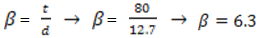
 If
If  have:
have: The total resistance (Rvd) is the result of the product of the resistance (Rvd,1) the amount of bolts in the connection, then for two bolts:
 A2 - Determination of maximum strength on the connection: Model 10.0 cm x 30.0 cm with three bolts without plate.Calculation of

 The resistance of various bolts corresponding to the cutting plane (Rvd) and is the result of the resistance of a product corresponding to the section plane (Rvd,1) the quantity of the bolts connection bolt. Then:
 A3 - Determination of maximum strength on the connection: Model 10.0 cm x 40.0 cm with four bolts without plate.
 However, the two bolts, one notes that the model presents crack in the wood along and toward the lower bolt, where the stress is applied perpendicular to the grain, tending to chip the wood by bending, because in this region the fibers are tensioned.
 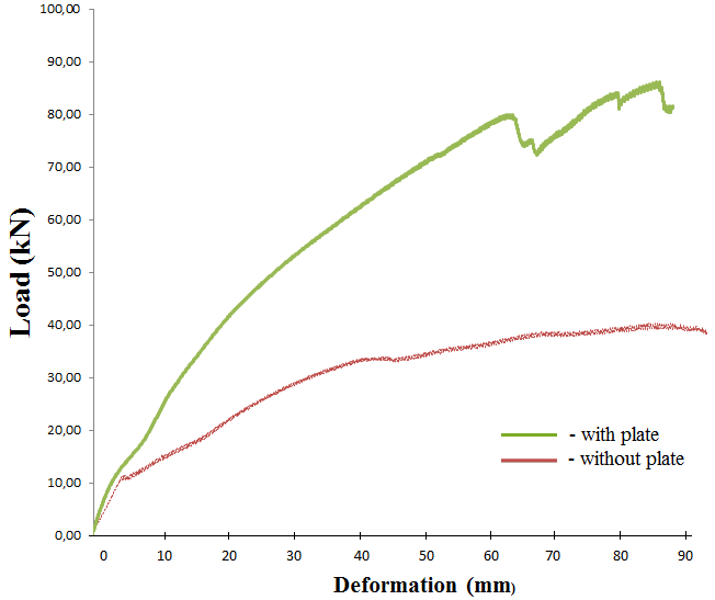 | Figure 5. Load resistance to compression connection with two bolts |
The graphs showed that to compression shear test (Figures 6, 7 and 8) where the load, was applied to register the exact tension that initiates the deformations in the joints.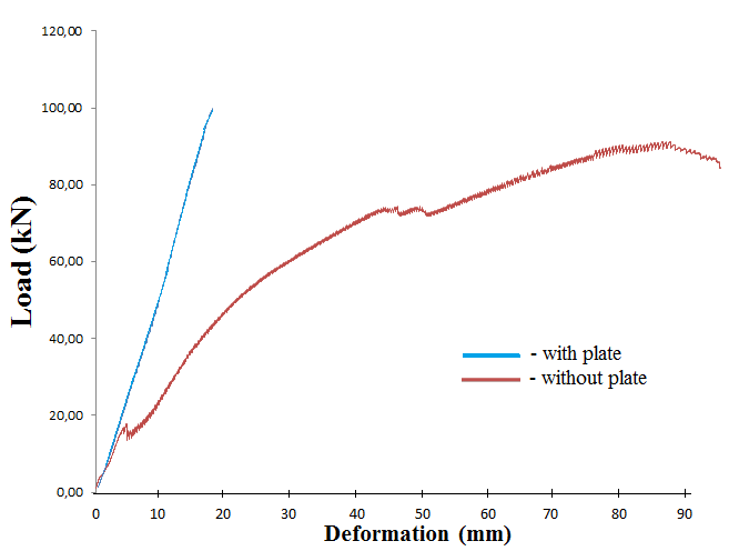 | Figure 6. Load resistance to compression connection with three bolts |
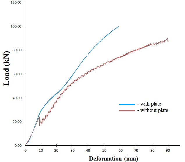 | Figure 7. Load resistance to compression connection with four bolts |
The maximum load for the set with three bolts, before the beginning of the smashing of the wood fibers occurs by bolts, was around 16.8 KN by the stress-strain graphics (Figure 7), with deformation smaller than 2.0 mm, which analytical calculations by the tension was 16.02 KN, without deformation, which shows the results efficiency and certainly.On the other hand the maximum load recorded for models A1 and B1, with and without the plate before it happened early crush the fibers of the wood by bolts, was approximately 11.0 kN, the physical test with a deformation below 2.0 mm, while tension of the analytical calculation is 8.46 kN without deformation, suggesting an error of approximately 30%. However the maximum stress, the A3 and B3 model, with and without plate before the start of the crushing of the wood fibers occur, was approximately 24.2 kN with a smaller deformation than 3.0 mm and the load as analytical calculation was 21.36 KN, without deformation, implying errors of the order of 11%.Note that the calculations and graphics load-strain showed well correlated, which demonstrates the efficiency of the results practical obtained.On the other hand, when we perform the simulations by Software FEMAP-Finite Element Modeling and Post-processing/NASTRAN, we aimed to evaluate the stress distribution in the regions of active tension. This allowed modulate the deformation of the wood and the connecting element bolt, and also in other situations as reported by [6] and [7].The applied tension in the specimens exerts shear forces on the spindle, which are distributed on the amount in of bolts connection as related for [8] and [9].So because the bolt positioned at the bottom, suffer greater resistance from the wood, try to have a larger deformation. This phenomenon is best seen in the model that used three bolts on the set, where the positioned closer to the applied load, penetrate the wood more, the middle has lower request, and is positioned below most requested by that is forced by the wood that is over it and also because the top of the wood to be the first to enter fatigue according to [10] and [11], as can be seen in (Figures. 8, 9 and 10), where a simulation treatment was performed.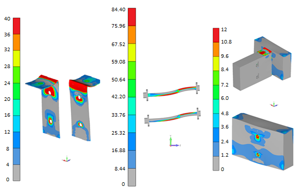 | Figure 8. Sections for distributing compression loads for bolts in medium carbon steel (grade 5) in connection wood/wood, wood/plate/wood with two bolts |
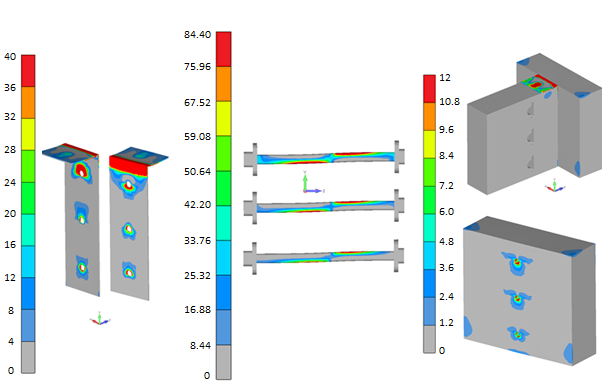 | Figure 9. Sections for distributing compression loads for bolts in medium carbon steel (grade 5) in connection wood/wood, wood/plate/wood with three bolts |
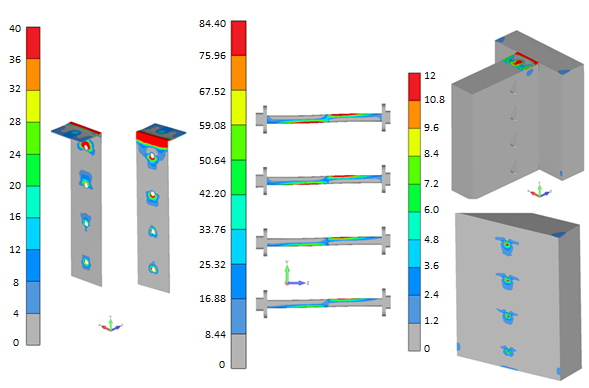 | Figure 10. Sections for distributing compression loads for bolts in medium carbon steel (grade 5) in connection wood/wood, wood/plate/wood with four bolts |
The results this study with the FEMAP, also was well demarcated from the stresses of the locations of the farthest bolt load application region. Therefore both results denote that the wood in the longitudinal position in this region received normal traction forces to the fibers arising from the tension caused by the bolt in the parts with and without the metal plate between them.
4. Conclusions
The results allowed determining the stiffness in service, the slip at failure and the reference loads (proportional limit, yielding, ultimate). A decreasing ductility of joints was observed at the increase of the number of bolts.It was observed that the insertion of a metal plate between the pieces of wood increased by about 50% in the shear strength of the connection. The models A1 and B1, with two bolts with or without plate, were the ones with least resistance, while with three bolts were most loads resisted. The B2 model with three bolts and the plate pressed between the pieces, which was performed best against the resistance of the shear stress, together with both the wood/wood connections, as for all wood/plate/wood.However, the B2 model with three bolts with plate resisted a higher load to the A3 model with four bolts and without plate. Therefore, as the size of the wood pieces and the diameter of the bolts used, the pressed plate metal inserted between the pieces, reasonably suggests a decrease in deformation of connection elements. Future research within these parameters can be developed for this certification, aiming due employability of wood, screws and connections with other auxiliary metallic elements, which were not exposed, and coming to play an important role of technology and innovation in engineering and architecture of constructions.
ACKNOWLEDGEMENTS
The author thanks main the CAPES and Foundation ARAUCÁRIA of the BRAZIL who approved resource for the student work, and to support of the UTFPR - Cornélio Procópio - PR which was sufficient for the development work.
References
| [1] | H. Isoda, M. Tachibana, N. Kawai and M. Koshihara, Case Study of Combination Ways of Steel and Timber in Japanese Buildings WCTE – World Conference on Timber Engineering (2010). |
| [2] | C.F. Bremer, and E. Carrasco, Parafusos ocos em ligações de peças de madeira laminada colada, Revista de Engenharia e Tecnologia, Brazil, Vol. 5 n 1 p. 59-69(2013). |
| [3] | J.C. Molina and C. Calil Junior, Wood frame systems for wood homes, Ciências Exatas e Tecnológicas, Brazil, Vol.31 n.2 p. 143-156 (2010). |
| [4] | S.H. Ju, C.Y. Fan and G.H. Wu, Three-dimensional finite elements of steel bolted in connections, Engineering Structures, Vol.26: p. 403–413(2004). |
| [5] | F. Lam, M. Gehloff and M. Closen, Moment-resisting bolted timber connections, Proceedings of the Institution of Civil Engineers Structures and Buildings, Vol. 163(4) p. 267-274 (2010); doi: 10.1680/stbu.2010.163.4.267. |
| [6] | L.B. Sandberg, W.M. Bulleit and E.H. Reid, Strength and stiffness of oak pegs in traditional timber-frame joints, Journal of structural engineering, Vol.126 p.717-723 (2000) doi:http://dx.doi.org/10.1061/(ASCE)07339445(2000)126:6(717). |
| [7] | A.K. Dessouki , A.H. Youssef and M.M. Ibrahim, Behavior of I-beam bolted extended end-plate moment connections, Ain Shams Engineering Journal, Vol. 4 n.4 p. 685-699 (2013), doi: 10.1016/j.asej.2013.03.004. |
| [8] | E. Mashaly, M. El-Heweity, H. Abou-Elfath and M. Osman, Behavior of four-bolt extended end-plate connection subjected to lateral loading, Alexandria Engineering Journal, Vol.50 n.1 p. 79-90, doi: 10.1016/j.aej.2011.01.011. |
| [9] | R.E.S. Ismail, A.S. Fahmy, A. M. Khalifa and Y. M. Mohamed, (2014) Behavior of End-Plate Steel Connections Stiffened with Stiffeners of Different Geometrical Dimensions, Global Advanced Research Journal of Engineering, Technology and Innovation, Vol. 3 n.3 p. 55-69. |
| [10] | C.D.M. Victoria, P. Martí and O.M. Querin, (2011) FE model of beam-to-column extended end-plate joints, Journal of Constructional Steel Research, Vol.67 p. 1578–1590. |
| [11] | M.E. Lemonis and C.J. Gantes, Mechanical modeling of the nonlinear response of beam-to-column joints, Journal of Constructional Steel Research, 2009, Vol. 65(4), pp. 879-890. |
 Abstract
 Reference
 Full-Text PDF
 Full-text HTML