-
Paper Information
- Previous Paper
- Paper Submission
-
Journal Information
- About This Journal
- Editorial Board
- Current Issue
- Archive
- Author Guidelines
- Contact Us
American Journal of Materials Science
p-ISSN: 2162-9382 e-ISSN: 2162-8424
2014; 4(5): 190-193
doi:10.5923/j.materials.20140405.02
A Non-polluting Option Using Cathodic Protection for Hydrostatic Testing of Petroleum Tanks with Seawater
Fernando B. Mainier1, Laerce de P. Nunes2, Luis P. Gomes2, Antonio Carlos M. da Rocha1
1Escola de Engenharia, Universidade Federal Fluminense, Niterói, RJ, Brazil
2IEC – Instalações Engenharia de Corrosão, Rio de Janeiro, Brazil
Correspondence to: Fernando B. Mainier, Escola de Engenharia, Universidade Federal Fluminense, Niterói, RJ, Brazil.
| Email: |  |
Copyright © 2014 Scientific & Academic Publishing. All Rights Reserved.
Oil storage tanks and derivatives must be evaluated by hydrostatic testing for leaks in sideways welds, possible cracks and failures that may have occurred during construction. Also in this test are observed defects and cracks in the concrete foundations that support the tank on the ground. The use of seawater as a fluid for hydrostatic testing in storage tank is economically attractive when the storage tanks are located near the sea. Due to its corrosive nature, seawater can cause damage to the internal surface of storage tanks. Generally, corrosion inhibitors and biocides are added to seawater in order to keep the corrosion rate under control. The disposal of water used in hydrostatic testing can represent an environmental problem whereas most corrosion inhibitors are toxic. Hydrostatic tests were run on bench scale tanks to investigate the efficiency of cathodic protection. These tests indicated that an aluminum anode (sacrificial anode) can efficiently replace corrosion inhibitors in storage tanks with the advantage that this corrosion protection system is not hazardous to the environment, as corrosion inhibitors can eventually be. The fixing of anodes in rubber floats and tubular modules represent a major innovation in the inner protection of tanks during the hydrostatic test with sea water.
Keywords: Corrosion, Hydrostatic testing, Cathodic protection, Petroleum tank, Failures
Cite this paper: Fernando B. Mainier, Laerce de P. Nunes, Luis P. Gomes, Antonio Carlos M. da Rocha, A Non-polluting Option Using Cathodic Protection for Hydrostatic Testing of Petroleum Tanks with Seawater, American Journal of Materials Science, Vol. 4 No. 5, 2014, pp. 190-193. doi: 10.5923/j.materials.20140405.02.
Article Outline
1. Introduction
- Industrial production processes, mainly chemical, petroleum and metallurgical, continue to exert strong pressure on the environment considering the inherent risks of their processes and equipment. The international media have highlighted a series of accidents involving spills, disposals, and contaminations with large environmental impact, including evacuations of entire communities on the basis of leaks of toxic gases and liquids, pollution, associated diseases and even deaths. All these facts are intended to show those responsible for large industrial complexes the need to respect the integrity of equipment standards and directives on environmental preservation. In addition, it is essential to develop clean technologies and secure systems to avoid environmental disorders. Their goal is to make the planet safer and less polluted. Therefore, it is very important to articulate the integration of environmental agencies, public health, safety and industrialization with the larger society organized to establish standards and procedures in order to ensure real quality of life [1].The objective of hydrostatic testing on storage tanks of petroleum, petroleum products, and other liquid products is to identify possible defects, cracks or construction failures that may occur during their assembly, operation or mechanical repairs and also assess the state of reinforced concrete foundations that support such tanks on the ground. Hydrostatic testing is universally known and accepted as a means to demonstrate the fitness of a pressurized component for service.There are various existing international standards for the design of petroleum installations, including the design and construction of low pressure, low temperature tanks for the storage and handling of petroleum products. The procedures adopted in hydrostatic testing are conducted in four stages filled with sea water for five days in each step. In the first step the filling is of 1/4 of the total volume, in the second half, the third represents 3/4 and finally the last comprises the filling up to 20 cm below the top edge.It is important to note that hydrostatic testing with pressurized water contributes effectively to the security of the enterprise; however, the inspection of welds by specific techniques (ultrasound, x-rays, etc.) before and after hydrostatic testing are also fundamental in the industrial assembly. Still, it is important to note that hydrostatic testing should be performed at necessary and sufficient time intervals for a safe and correct response to the industrial assembly process.In regions near the sea and lacking fresh water it is common to use seawater in the hydrostatic testing of pipelines, considering the runtime of the test and despite the significant possibility of generalized corrosion, pitting and corrosion by bacteria. To avoid or minimize problems with corrosion, corrosion inhibitors and biocides are commonly used. However, environmental agencies do not always allow this alternative, considering its toxicity in relation to environmental disposal of the test water in the sea itself. In most cases fresh water is the preferred choice to avoid the possibility of internal corrosion by seawater that can compromise the integrity of the enterprise according and cause a loss of thickness in the ducts [2].Hydrostatic testing of large storage tanks of oil and oil derivatives located in marine regions preclude the use of fresh water because it becomes too expensive considering the large volume of water used in testing and the cost of pumping fresh water from reservoirs or transporting it on barges (service ship). Considering these facts, the low cost of seawater is quite attractive. However, experience shows that severely corrosive seawater can compromise the bottom and sides of a tank, as shown in several photos (Figure 1) taken inside oil storage tanks.
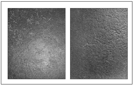 | Figure 1. Aspects of internal corrosion of petroleum tanks |
2. Galvanic Cathodic Protection as an Anti-corrosion Technique not Harmful to the Environment
- The galvanic cathodic protection mechanism shown in Figure 2 is not novel, because the use of aluminum and zinc anodes in protecting ships, pipelines, oil production platforms, tanks, piers and submarines is an accepted practice worldwide [7, 8, 9].
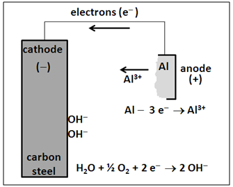 | Figure 2. Cathodic protection mechanism with aluminum anode |
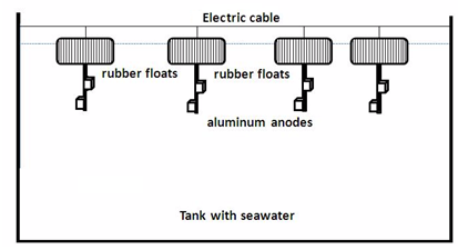 | Figure 3. Rubber float with an aluminum anode connected with an electric cable on the tank |
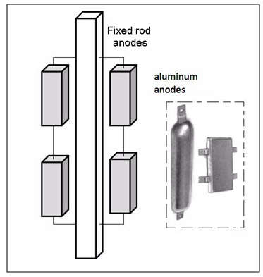 | Figure 4. Rod fixed on aluminum anode |
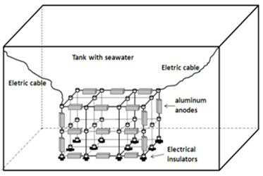 | Figure 5. Distribution of anodes in tubular module |
3. Laboratory Experiments
- To demonstrate the use and good performance of cathodic protection with aluminum anodes two experiments were carried out. The first consisted of an acrylic container with a volume of 60 L and the other a small carbon steel tank with a capacity of 200 L.
3.1. Evaluation in the Laboratory of Carbon Steel Plates in Seawater
- This assay consisted, essentially, in placing two carbon steel plates (20 cm × 10 cm) fixed in a holder and immersed in a transparent acrylic container with a capacity of 60 L of solution containing 3.5% (by weight) sodium chloride representing seawater, as shown in Figure 6. A carbon steel plate was connected to an aluminum anode while the other metallic plate was unprotected. Potential measurements were made twice daily to evaluate the cathodic protection. An agitator and an air bubbler were added to the system to generate oxygenation and a corrosive environment.
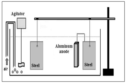 | Figure 6. Assay of cathodic protection with galvanic anodes |
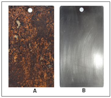 | Figure 7. (A) Steel plate after fifteen days in seawater; (B) Steel plate with cathodic protection |
3.2. Evaluation of the Internal Protection of a Carbon Steel Tank with a Capacity of 200 L (Internal Area 1.8 m2) Filled with Seawater (3.5% NaCl)
- The test consisted of placing 2 rubber floats attached to five aluminum anodes weighing 50 g connected with electrical cable in the tank. The current required for cathodic protection and the mass of the aluminum anodes was estimated based on the simplified equations:
 Where:I= current output (A)S = surface, m2d = current density = 0.08 a/m2δ = coating factor = 0 (uncoated)MAl = mass of the anode (kg)T = hydrostatic test timeF = utilization factor = 0.8C = anode current capacity = 1800 A.h/kg The aluminum anodes were analyzed and revealed the chemical composition presented in table 1:
|
4. Conclusions
- On the basis of the above it is concluded that:• The laboratory tests carried out with aluminum anodes in seawater showed excellent protection of carbon steel;• The use of seawater instead of using fresh water in hydrostatic tests of pressurized tanks near the sea is much more advantageous in relation to the cost of transporting treated fresh water;• It is a fact that the corrosion caused by seawater is more intense than fresh water corrosion;• The provisional system of cathodic protection technology proposed with rubber floats attached to aluminum anodes or metallic modules with aluminum anodes represents a technological innovation and can be successfully used in hydrostatic testing with seawater in place of the addition of corrosion inhibitors, since it avoids corrosion and environmental damage; • The use of corrosion inhibitors in hydrostatic tests can itself engender environmental contamination unless the formulations are biodegradable or innocuous to the environment;• Finally, whereas the majority of corrosion inhibitors is toxic, this technology represents an advance in environmental protection.
 Abstract
 Reference
 Full-Text PDF
 Full-text HTML