-
Paper Information
- Paper Submission
-
Journal Information
- About This Journal
- Editorial Board
- Current Issue
- Archive
- Author Guidelines
- Contact Us
American Journal of Materials Science
p-ISSN: 2162-9382 e-ISSN: 2162-8424
2014; 4(1): 1-6
doi:10.5923/j.materials.20140401.01
Characterisation and the Influence of Voids on Flexural and Tensile Modulus of Layered Silicate/Vinyl Ester Nanocomposites
 Abstract
 Reference
 Full-Text PDF
 Full-text HTML
A. I. Alateyah1, 2, H. N. Dhakal2, Z. Y. Zhang2
1Al Imam Mohammad Ibn Saud Islamic University (IMSIU) (Riyadh, Saudi Arabia)
2Advanced Polymer and Composites (APC) Research Group, School of Engineering, University of Portsmouth, PO1 3DJ, UK
Correspondence to: A. I. Alateyah, Al Imam Mohammad Ibn Saud Islamic University (IMSIU) (Riyadh, Saudi Arabia).
| Email: |  |
Copyright © 2012 Scientific & Academic Publishing. All Rights Reserved.
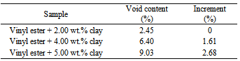
In this work, the flexural and tensile moduli of the neat vinyl ester and the corresponding nanocomposites are investigated. In addition, the influence of the voids content of the nanocomposites on the mechanical modulusis presented. Various amounts of clay were used in this work which include 2, 4, and 5 wt.% clay loading. To characterise interlaminar structure of the nanocomposites, XRD, SEM and TEM were performed. The mechanical modulusof the neat sample was improved by the incorporation of layered silicate up to 4 wt.%. Further addition of layered silicate resulted in decreasing the modulusproperties. This was due to the presence of high numbers of microvoids in the nanocomposites structure at high clay loading. The increment in microvoids content was proportional to the clay loading. At 2 wt.% clay content, the voids were about 2.45 %. However, at 4 and 5 wt.%, the voids amount represented 6.40% and 9.03 % respectively.
Keywords: Nanocomposites, Vinyl ester, Layered silicate, Microvoids
Cite this paper: A. I. Alateyah, H. N. Dhakal, Z. Y. Zhang, Characterisation and the Influence of Voids on Flexural and Tensile Modulus of Layered Silicate/Vinyl Ester Nanocomposites, American Journal of Materials Science, Vol. 4 No. 1, 2014, pp. 1-6. doi: 10.5923/j.materials.20140401.01.
Article Outline
1. Introduction
- Polymers with various particulate fillers have been successfully reinforced to improve their mechanical, thermal, and barrier properties[1-5]. The presence of the traditional fillers usually results in unwanted properties such as brittleness and opacity. Thus, polymer-clay nanocomposites (PCN) have attracted considerable interest because of the enhancements in various properties without sacrificing the opacity and brittleness[6]. PCN often provide more attractive improvements to material properties than both micro and macro composite materials[7-12]. The improvements include mechanical, thermal, barrier, and flame retardance properties. In addition, the incorporation of layered silicate into the polymer matrix usually results in improvement of the polymer performance[13]. These improvements can be achieved only by the addition of less than 5 wt.% clay into the neat matrix[14). The type of clay used, the kind of pre-treatment, the polymer component chosen and the way in which the nanocomposite incorporates the polymer, can have a profound influence both on the properties and the structure of the nanocomposite[15, 16]. The reason for improvement of the material properties is the aspect ratio of the layered silicate where the interfacial interaction between the organically modified layered silicate and the matrix is higher than traditional composites. Layered silicate has a thickness of sheet in the order of 1 nm and a very high aspect ratio. A little weight percent of OMLS is dispersed throughout the matrix, thus giving a larger surface area for polymer filler interfacial interaction than in conventional composites[16-18]. In this context, the investigation of the mechanical properties, including tensile and flexural modulus, of the neat vinyl ester and corresponding nanocomposites took place. Moreover, this study aims at analysing the influences of microvoids existing in the nanocomposites structure in the flexural and tensile modulus.
2. Experimental
2.1. Materials
- The matrix material used in this study is vinyl ester (VE) resin. “Vinyl ester resins are oligomers resulting from the reaction between bisphenol-A based epoxy oligomers and unsaturated carboxylic acids, such as acrylic or methacrylic acid, which provide unsaturated terminal sites”[19]. This material was purchased locally and commercially coded as AME 6000 T 35. The layered silicate that has been used is Cloisite® 10A which is classified as a natural montmorillonite that is modified with a quaternary ammonium salt; it was purchased from Southern Clay Ltd. This clay can be used to improve different physical properties such as barrier, flame retardance and reinforcement[20].
2.2. Sample Fabrication Process
2.2.1. Neat Vinyl Ester
- In order to make neat vinyl ester panels, the vinyl ester was directly mixed with the curing agent (Methyl ethyl ketone peroxide(MEKP) (mix ratio 1.5%) and then was poured in a steel mould. The mould was closed and the composite panel was left to cure in a hydraulic press at a temperature of 55°C and at a compaction pressure of 1 MPa for 2 hours.
2.2.2. Nanocomposites
- Combinations of melt intercalation method with the compression moulding method were used to fabricate nanocomposite panels. The vinyl ester resin was mixed with various concentrations of nanoclay at room temperature using a mechanical mixer in an ultrasonic bath for 2 hours. A degassing process was applied in the mixture for 3-4 hours then it was left overnight in order to get rid of the remaining air bubbles naturally. A curing agent (MEKP) was added to the mixture (1.5%) with further gentle mixing before transfer of the mixture to the steel mould. The mould was closed and the composite panel was left to cure in a hydraulic press at a temperature of 55°C and at a compaction pressure of 1 MPa for 2 hours. A post curing process of neat and nanocomposites samples were followed at 80°C for 3 hours. The clay loadings were 0, 2, 4, and 5 wt.%.
2.3. The Calculation of Nanocomposites Voids Volume
- Nanocomposites voids were calculated by using the following equation;
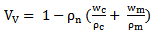 | (1) |
 the density of nanocomposites,
  the weight percent of clay (%),
 the density of clay g/cm3, wm the weight percent of matrix (%) and
  is the density of matrix g/cm3. The density of nanocomposites was calculated as following;
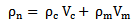 | (2) |
 are the volume fractions of clay and matrix, respectively
2.4. Characterisation
2.4.1. Wide Angle X-ray Diffraction (WAXD)
- WAXD analysis on compression-moulded specimens was used to determine the clay intercalation and interlayer spacing utilising a Philips APD 1700 X-ray diffraction system with Cu Kα radiation (λ = 1.542A) generated at 40mA and 40 kV. The basal-spacings (the d-spacing, in Angstroms, between layers) were calculated using Bragg’s Law.
2.4.2. Scanning Electron Microscopy (SEM)
- The morphology of vinyl ester /nanocomposite systems was investigated in a Hitachi S4500 SEM working at an operating voltage of 8 kV. Block faces were prepared from each material then ultrathin sections (63nm) were collected using a diamond knife in a Reichert Ultracut E ultramicrotome. Plasma etching was used to preferentially remove the vinyl ester matrix and leave the clay particles sitting proud of the surface. After adhering to SEM stubs, a thin layer of gold/palladium was applied to the specimens prior to examination in a Quanta 250 FEG SEM.
2.4.3. Transmission Electron Microscopy (TEM)
- TEM measurements on vinyl ester/nanocomposite systems were performed using a high-resolution transmission electron microscope (Phillips CM12 with an associated Gatan digital camera system). The same block faces used to produce the sections for SEM examination were also used for TEM.
2.5. Testing
2.5.1. Flexural Test
- The flexural properties modulusof the neat vinyl ester and the corresponding nanocomposites samples were investigated by using the 3-points bending test process under the specification of BS EN 2747:1998[21]. A span of 48 mm length was utilised in a 30 kN load cell. The load was applied midway between the supports. The speed of crosshead was 2 mm/minute. The neat and nanocomposites samples were loaded until any failure was observed and then their average values were calculated.
2.5.2. Tensile Test
- The tensile modulusof neat polymer and nanocomposites samples were carried out at a crosshead speed of 10 mm/minute under BS EN 2747:1998[22]. The tensile test specimens were prepared by utilising a water jet into rectangle beams from the nanocomposites slabs fabricated by a compression moulding method.
3. Results and Discussion
3.1. Nanocomposites Voids Content
- The voids content in nanocomposites felid is a big concern for the industrial or engineering designs. The pre-failure and the promoting of the local deformation of the applications can be obtained by the existence of high content of microvoids[23]. Thus the study of the parameters which influence the content voids as well as the percentage of these values can help to improve or maintain the quality of samples fabricated. The voids content in the nanocomposites sample were calculated using equations (1) and (2) and the results are presented in Table 1. The amount of voids was increased with the increase in clay loading.
|
3.2. Characterisations of the Interlamellar Structure and Surface Morphology
3.2.1. Wide Angle X-ray Diffraction (WAXD)
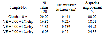
- Wide Angle X-ray Diffraction (WAXD) is a method broadly utilised in the study of intercalation or exfoliation which additionally characterises nanocomposites and the study of the interaction between layered silicate and the matrix. Nanocomposites show dramatic enhancement in properties when neat polymers are compared with polymers based on modified layered silicate. These improvements are attributed to the sufficient dispersal of layered silicate within a polymer matrix. A micro-composite structure is obtained when a weak interaction occurs between the clay and the matrix. X-ray diffraction is utilised to show the intercalation or exfoliation structures by calculating the intergallery spacing, in order to identify the structure of the nanocomposite[24]. In this section, the amount of d-spacing of the intergallery is presented and discussed for different clay loading nanocomposites as well as for neat polymer. Table 2 represents the change of the basal spacing (doo1 spacing) of different samples of nanocomposites that were calculated by Bragg’s Law using the values extracted from the XRD curves. From Table 2 and Figure 1, it can be seen that the nanoparticles reinforced samples show various x-ray diffraction patterns. The 2θ value for only Cloisite 10 A was 20° which represents 0.443 nm basal distance. The first peak at 2θ value of 16.86° (2% w/w clay reinforced sample) illustrates the partial intercalated d-spacing of the clay at approximately 0.525 nm with an improvement of the d-spacing about 18.51% compared to base clay. By the addition of 4 wt.% layered silicate, the 2θ exhibited less amount than the previous clay loading which was 13.84° and displayed 0.639 nm of the interlayer spacing. The peak for the 5 wt.% clay loading sample at 2θ value has shifted towards a higher angle (16.08°) which indicated lees intercalated d-spacing of 0.551 nm.
|
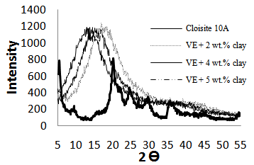 | Figure 1. XRD results of neat polymer and the corresponding nanocomposites |
3.2.2. Scanning Electron Microscopy (SEM)
- The SEM examination in Figure 2 shows clearly the distribution of the clay through the vinyl ester for each of the three levels of loading. As the selected images show below, the largest clay agglomerates are of a similar size for all three samples, being around 30 to 35 microns in size. However, their frequency increases with increase in loading, as does the degree of infilling between them with smaller agglomerates. Also, the voids were found to be increased with the increase in the clay content. It can be seen that the 2 wt.% clay loading shows non pronounced stacked layers and uniform distribution. The addition of further clay (i.e 4 wt.%) showed uniform ditrbution of particle with little sheets agglomeration. The SEM image of 5 wt.% clay loading exhibited a high number of stacked clay particles and voids compared to 2wt.% and 4 wt.%clay.
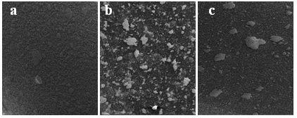 | Figure 2. SEM images at 300 µm of (a) 2 wt.%, (b) 4 wt.% and (c) 5 wt.% nanocomposites |
3.2.3. Transmission Electron Microscopy (TEM)
- Figure 3 shows the TEM micrographs of 2, 4 and 5 wt.% nanocomposites samples at 0.2 µm magnification, where the bright region represents the matrix sea and the dark lines correspond to the stacked or individual silicate layers. Indications are from the higher magnification images that greater levels of exfoliation of the clay particles are achieved with lower nanoclay loading. At 2 wt.% clay loading, the TEM image indicates good dispersion of layered silicate throughout the polymer matrix.
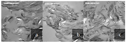 | Figure 3. TEM micrographs at 0.2µm magnification of (a) 2 wt.%, (b) 4 wt.% and (c) 5 wt.% nanocomposites |
3.3. Flexural Modulus
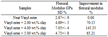
- The average results obtained from the four specimens tested are represented in Table 3. These show a significant enhancement in flexural modulus for nanocomposites compared to neat matrix samples. The flexural modulus for the neat sample were 2.87GPa, whereas for 2 wt.% clay loading the modulus was 4.89GPa, which was an improvement of about 70%. At 4 wt.% clay loading, the flexural modulus represented 7.05GPa. The addition of more clay (i.e 5 wt.%) showed a reduction in the modulus and exhibited 4.75GPa. The significant improvement in the 4wt.% clay loading is attributed to the properly dispersed layered silicate within the host polymer as proved by XRD, SEM, and TEM.
|
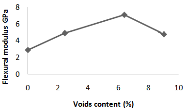 | Figure 4. The relationship between the voids content and the flexural modulus |
3.4. Tensile Modulus
- Four specimens in each loading were tested and the averages of those outcomes were obtained and are presented in Table 4. Table 4 and Figure 5 represent the enlargement of the amount of tangentmodulus for nanocomposite samples compared to the pristine one. The clay loading had a strong influence on the modulus as the results were increased by the addition of nanoparticles. For example, neat vinyl ester, 2wt.%, 4 wt.% and 5 wt.% layered silicate represented 1.19, 1.46, 1.70 and 1.55GPa respectively. Again, the voids played an important role in terms of modulus since the high number of voids will reduce the interfacial interaction between the layered silicate and polymer, in turn, less polymer physisorption forces onto the monolayer will take place[31] as depicted in figure 5.
|
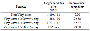
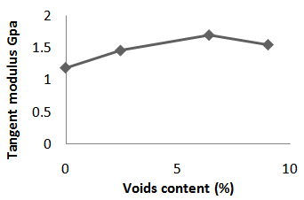 | Figure 5. The influence of the voids content on the tangentmodulus |
4. Conclusions
- Flexural and tensile modulus of vinyl ester matrix based on layered silicate was investigated. In addition, the effect of the percentage of microvoids in the nanocomposites structure on the flexural and tensile modulus was discussed. The layered silicate had a strong effect on the polymer properties. The higher the amount of clay loading, the better the matrix properties achieved, up to 4 wt.% clay. Further addition of clay resulted in decreasing the nanocompositesmodulus which could be traced to the presence of the high amount of microvoids as calculated.