Lucian Capitanu1, Virgil Florescu2
1Tribology DepartmentInstitute of Solid Mechanics of the Romanian Academy, Bucharest, Postcode, 010141, Romania
2Mechanical Departatment , Institute of Civil Engineering, Bucharest, Postcode, 050153, Romania
Correspondence to: Lucian Capitanu, Tribology DepartmentInstitute of Solid Mechanics of the Romanian Academy, Bucharest, Postcode, 010141, Romania.
| Email: |  |
Copyright © 2012 Scientific & Academic Publishing. All Rights Reserved.
Abstract
It is generally known that the friction and wear between polymers and polished steel surfaces has a special character, the behaviour to friction and wear of a certain polymer might not be valid for a different polymer, moreover in dry friction conditions. In this paper, the reaction to wear of certain polymers with short glass fibres (polyamide + 20% glass fibres, polyamide + 30% glass fibres and polycarbonate with 20% glass fibres) on different steel surfaces was studied, considering the linear friction contact, observing the friction influence over the metallic surfaces wear. The paper includes also its analysis over the steel’s wear from different points of view: the reinforcement content influence and tribological parameters (load, contact pressure, sliding speed, contact temperature, etc.). Thus, authors' findings related to the fact that the abrasive component of the friction force is more significant than the adhesive component are presented, which generally is specific to the polymers’ friction. Authors’ detections also state that, in the case of the polyamide with 30% glass fibres, the steel surface linear wear rate order are of 10-4 mm/h, respectively the order of volumetric wear rate is of 10-6 cm3 /h. The resulting volumetric wear coefficients are of the order (10-11 – 10-12) cm3/cm and respectively linear wear coefficients of 10-9 mm/cm.
Keywords:
Friction, Wear, Composite Thermoplastics, Comparative Wearing Coefficient
Cite this paper: Lucian Capitanu, Virgil Florescu, Tribological Aspects of Wear of Polished Steel Surfaces in dry Friction Contact on Polymer Composites with Glass Fibres, American Journal of Materials Science, Vol. 3 No. 1, 2013, pp. 8-18. doi: 10.5923/j.materials.20130301.02.
1. Introduction
The tribological behaviour of polymers has distinctive characteristics, some of them being described by Bowden and Tabor[1]. The main concept related to the polymers’ tribology is composed of three basic elements involved in friction: (i) junctions adhesion, their type and resistance; (ii) materials’ shearing and fracture through friction during the contact; and (iii) the real contact area.Friction’s straining component results from the polymer’s resistance to “ploughing” made by the asperities existing on the harder counter-face. The polymer’s surface asperities bears elastic, plastic and viscous-elastic strains, according to the material’s properties. Friction adhesion component comes out of the adhesion junctions formed on the real contact spots between the paired surfaces. Friction adhesion component in what the polymers are concerned is considered to be much greater than the straining component. Special attention should be granted to the transfer films, these transfer films being the key factors determining the tribological behaviour of polymers and polymeric composites. In what the glass fibres reinforced polymer is concerned, was also encountered a strong abrasive component[2].Several models were developed to describe the contact adhesion. The Johnson-Kendall-Roberts (JKR) model, mentioned sometimes as the contact mechanics model[3-4] and the Derjaguin-Muller-Toporov (DMT) model[5] are the best known. The models’ comparative analysis[6] shows that the JKR model is applied to bodies with micrometric dimensions and larger than that, with polymer properties, whilst the DMT model is valid for bodies with nanometer dimensions, with metal properties. Accordingly, will be further briefly discuss the JKR model.The JKR model is based on the hypothesis of an infinite small radius in what the surface forces effect is concerned, that supposes that the interactions take place only in the contact area. The elastic contact between a sphere with an R radius and a semi-infinite plain is analysed by taking into consideration the van der Waals forces, which attract the bodies paired together, in addition to the applied load. The molecular interaction energy is  . The rigidity of contact bodies resists to the impact of the force. By using the energy balance equations the contact main parameters are being derived, based upon a combination between the hertzian pressure distribution (loading) and the Boussinesq pressure distribution (unloading). Such a combination produces compression in the middle of the contact and an infinite tension at its edges.Adhesion’s contact a radius calculus formula is:
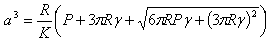 | (1) |
where  is the elastic constant, E is Young’s module, and P is normal load.Consequently, it is obvious that, without adhesion (γ = 0) was obtained the Hertz equation, whilst if γ > 0, the contact area always surpasses the hertzian contact area under the same normal load P. It was noticed that when the contact is completely discharged (P = 0) the adhesion doesn’t disappear, but it registers a finite radius:
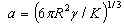 | (2) |
This radius may be reduced only by applying a pulling load (negative), and then, the contacting surfaces would separate at the least load corresponding to the radius modifying from equation (2) to zero: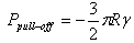 | (3) |
This circumstance represents the specific feature of JKR model. Several authors[8, 9-17] studied the polymers’ friction on hard surfaces. By using the method of contact’s conformity[18] they obtain the hardness, the deformability value (index) (which describes the coarse surfaces’ deformation properties), as well as the elasticity module for organic polymers polymethylmethacrylate – PMMA; polystyrene – PS; polycarbonate – PC, ultra high molecular weight polyethylene – UHMWPE. Was also described the dependence of the penetration depth, the maximum load and the sliding speed, of the hardness and the elastic modulus[19-22]. The typical penetrating depths are included within the approximate 10 nm to 10 μm range, whilst the applied loads are smaller than 300 mN. It can be observed the fact that almost without exception, the ploughing is accompanied by adhesion and in certain conditions it may lead to micro-cutting, which represents a supplementary adding to increase the friction force.There are other mechanisms to dissipate the energy while straining. For instance, whenever a polymer with viscous-elastic reaction slides on a hard surface, the energy dissipation is caused by the high losses through hysteresis. This straining component is known under the name of friction due to elastic hysteresis[1]. The energy can, as well, be transported further, for instance through elastic waves generated at the interface and coming out at infinit, as, a nucleation and micro-cracks development within the material, consequence[20]. The mechanical component is a reflection of the resistance of the softer material to the ploughing action of the harder asperities.The adhesion component comes of the adhesion junctions formed between the surfaces during the friction contact. It is believed that for polymers the adhesion molecular component exceeds by far the mechanical one[20]. It can be explained through the generated films’ transfer on the metal counter-face. It is paid special attention to the transfer films, as a key factor determining the polymeric materials’ tribological reaction. The following factors considerably affect the friction force: the contact load, sliding speed and temperature. The effects are not independent. For instance, as the contact load and speed vary, the temperature of the contact conjunction is altered, which affects the friction mode[21].
2. Materials and Methods
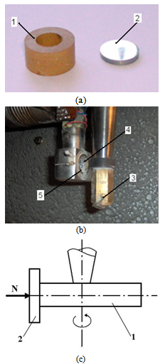 | Figure 1. Friction couple (a) and its installation in the experimental equipment (b), where 1 - cylindrical liner; 2 – steel disk sample; 3 – nut; 4 – hole; 5 - knife-edge, (c) the way how the liner moves against the disk |
In order to study the metallic counter-part’s wear in dry contact with glass fibres reinforced plastic materials Timken type friction couples (with linear contact), cylinder on plan are used, which allows to attain high contact pressures, hence high contact temperatures. In this matter it is possible to observe, whether and in which conditions the plastic material transfer to the metallic surface takes place as well as the influence of the glass fibres filling during this phenomenon, and its effect on the surface’s wear. As it is not followed the polymer’s wear, but only the polymer’s friction influence, over the samples’ metallic surfaces wear, is used the unidirectional sliding movement. The tests are performed using experimental equipment containing a Timken type couple with linear friction contact, continuously controlling the normal and friction loads, and contact temperature. The unidirectional movement and the linear contact allow to attain very high contact pressures and temperatures. The friction couple is built out of a plastic cylinder Nylonplast AVE polyamide + 30% glass fibres, which rotates at different speeds against the polished surface of a steel plan disk. The cylinder has an outer diameter of 22.5 mm and 10 mm height.Was chosen as sample steel disks with 18.2 mm diameter and 3 mm thickness. The disks’ surfaces were polished successively using sandpaper of different granulations (200, 400, 600 and 800) and, finally, were polished on the felt with diamond paste. Mirror polished surfaces, with roughness Ra of 0.05 µm were obtained. This metal surface’s quality allows to eliminate the influence of the metallic surface’s state on the friction coefficient’s evolution and visualization, to make measurements using optical microscopy and to accurately record the wear traces appeared on the metallic surfaces. Fig.1 shows the friction couple (a) and its installation within the experimental equipment (b). Modul in care se misca bucsa impotriva mostrei plane este ilustrat in Fig. 1c.Fig. 2 shows the scheme of the experimental equipment.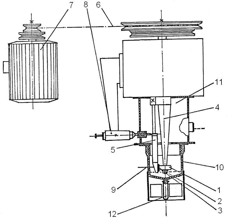 | Figure 2. The scheme of experimental equipment with linear contact friction couple, Timken type. |
The friction couple is build out of a cylindrical liner (1) and a plane disk type sample (2). The liner is fixed with the help of a nut (3) on the driving shaft (4). The disk sample is placed in a special hole made within the elastic blade (5). The sample disk base is built in such a manner so that the base allows the sample to make small rotations around the edge of a knife fixed in the sample’s bezel, perpendicularly on the driving arbor. In this way a uniform repartition of the load on the entire linear contact between the liner and steel sample is ensured, even if there are small building or assembling imperfections. An electric motor (7) puts the shaft (4) into a rotation movement using trapezoidal transmission belts (6). The normal and tangential (friction) efforts through resistive converter strain-gauges, assembled on the elastic blade (5). The use of a pair of converters strain-gauges connected within the circuits of two strain-gauges bridges, offers the possibility to make simultaneous measurements, while separately, gives the possibility to measure the normal and friction forces. The normal load to the elastic blade (5) is applied, through a calibrated spring system (8). The installation allows to register the friction force on an X-Y recorder. The tests’ duration is controlled through an alarm clock and the contact temperature is measured with the help of a miniature thermocouple (9), connected to a millivoltmeter calibrated in℃. The installation offers the possibility to study the wear behaviour by using also several other radiometers techniques. For this purpose, the installation includes a tank (10) assembled on a base (11) and a tube collecting the radioactive wear particles (12). The uni-directional testing was used because the purpose of investigations was the study of metallic surface wear. The tests are performed, based on Hooke's law, at normal loadings of 10; 20; 30; 40 and 50 N, loadings which are adequate to some contact pressures all calculated considering the elastic contact hypothesis, that is: 16.3; 23.5; 28.2; 32.6 and 36.4 MPa (for Nylonplast AVE polyamide with 30% glass fibres) respectively, sliding speeds are used, adequate to the diameter of the plastic composite sample, which are: 0.1856; 0.2785; 0.3713; 0.4641; 0.5570; 1.114 and 1.5357 m/s, and which resulted as a consequence of electric motor’s speed and the belt pulleys’ primitive diameters.As it is known[21], a material’s wear coefficient (percentage) may be characterized by wear factor k. Archard’s relation defines this factor: | (4) |
where: Vu – the wear’s material volume; N - the test load; v - the sliding speed; t - the test duration; k – volumetric wearing factor.By dividing both of this relation’s terms (4) by nominal contact area A, it is obtained: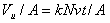 | (5) |
Which means that: | (6) |
where: hu - wear’s material depth; p - the pressure on the nominal contact area and k* is the linear wear factor. Relation (6) expresses a general law of the wear as a function of the contact pressure p and the length of the wear path, so that  It could be then written:
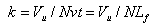 | (7) |
respectively: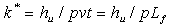 | (8) |
Considering the large area of the load (N) or pressure (p) and the relative speed values used during tests in order to evaluate the wear reaction of the metallic counter-pieces amid the frictional couples, are used comparative wear coefficients K and K*, defined by: | (9) |
 | (10) |
These wear coefficients are considered with respect to the duration in which the frictional couple functions at different sliding speeds, under certain loading conditions (contact pressure). The main objectives of these tests are the determination of the volume of material removed by wear, the mean depth of the worn layers, the frictional factors and coefficients, for different loading conditions.Coefficients k and k* are coefficients of the wear process, while the comparative factors K and K* are coefficients of this process’s consequences, that is, the amount of resulted wear and reported to the length of the friction pathway. They can be qualitatively expressed in units of wear volume on a measure of the length of the friction pathway (cm3 / cm), as wear’s depth on a measure of the length of the friction pathway (cm / cm) or as wear’s weight on a measure of the length of the sliding friction pathway (mg / cm). Coefficients K and K* have no mathematical implication (can not simplify).
2.1. Analytical Method
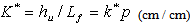
The Timken friction couple (with linear contact) subject to a certain load reveals the appearance of some wear traces on the plane surface of the metallic material. The wear trace is produced by the penetration of the plane semi-couple material by the cylindrical liner.Theoretically, if the liner is considered as rigid and accounting for the generally low non-uniformity of the imprint, it can be considered as being formed by a series of cylindrical sectors having the length q.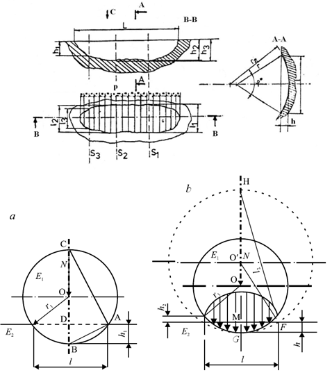 | Figure 3. The imprint scheme (top) and elastic deformation of the cylindrical liner in the contact area (bottom) for Timken friction couples (a – theoretical, and b – practical) |
Assuming that, the area of the lateral surface of the cylindrical sector is a circle segment, we have: | (11) |
where: Si - the area of the cross section of the worn surface; φ i- the angle; r - the circle radius.The radius r cannot be identified with the cylindrical liner radius related to the plastic/metal couples. This fact is possible due to the elastic deformation of the liner subject to a certain load conditions, which has as effect the increment of the radius in the contact area. This is illustrated in Fig. 3.Using the procedure described in[22], at the end the mean depth (12) and the volume of worn metallic material (13) are obtained: | (12) |
 | (13) |
where lm is the mean width of the wear imprint.Practically, the width of wear imprints in three points established before has to be measured, computing then the mean value of this width. With this value can be obtained the volume of worn metallic material Vu and the removed layer’s mean depth hmu.
2.2. Experimental Procedure
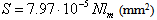
The wear of the friction couple’s metallic component on linear contact Timken machinery are studied, see Fig. 2. Almost all tests are made without lubricating the frictional surfaces. In order to calculate the metallic component’s wear, the method described above is used. The equations (11), (12) and (13) take into consideration, for the studied materials, particular forms obtained by introducing the interfering parameters numerical values, thus obtaining for a mean depth hmu and a worn material volume Vu the following relations:- Nylonplast AVE polyamide + 30% glass fibres/steel: | (14) |
 | (15) |
 | (16) |
- Lexan polycarbonate + 20% glass fibres/steel: | (17) |
 | (18) |
 | (19) |
 | (20) |
 | (21) |
 | (22) |
The studies concerning the metallic sample wear are generally based on the elastic contact hypothesis. For these plane half-couple the values for the equivalent elasticity module are:A. Nylonplast AVE polyamide + 30% glass fibres;E2A = 40.25 MPa. B. Noryl polyamide + 20% glass fibres; E2B = 31.76 MPa.C. Lexan polycarbonate + 20% glass fibres; E2C = 42.08 MPa.Assuming that the plastic liner does not crush, the condition pmax < 0.5H is imposed, where H stands for theBrinell hardness. The required condition allows to establish the following values of the maximum loadings (contact pressure) of the couple: pA1 = 16.3 MPa; pA2 = 23.5 MPa; pA3 = 28.2 MPa; pA4 = 32.6 MPa; pA5 = 36.4 MPa; pB1 = 12.3 MPa; pB2 = 17.4 MPa; pB3 = 21.4 MPa;pB4 = 24.6 MPa;pB5 = 27.6 MPa; pC1 = 16.9 MPa; pC2 = 23.9 MPa: pC3 = 29.3 MPa; pC4 = 33.8 MPa;pC5 = 37.8 MPa.The experimental tests are performed considering broader domains to vary the relative speed and normal loadings, or contact pressures. Couples with liner made from thermoplastic material with linear contact on a steel surface (C120, Rp3, a.s.o.) are used.
3. Results
3.1. Experimental results
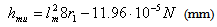
Table 1 is the representation of the experimental tests results, testing two friction couples, for one of the 8 different relative sliding speeds used. Table 1 represents the results of the tribological experimental tests, e.g. the mean values of the wear imprint depth hu (10−4 mm), and the average values of the worn material volume Vu (10−6 cm3). The average width lm represents the arithmetical average calculated based upon 3 measured values of the wear trace’s width. By dividing hu and Vu to the duration of experimental test, the values of the wear rate in terms of depth hmu(10−4 mm/h) and volume Vmu(10−6 cm3/h) are obtained.Based upon the methodology described above, the results are processed obtaining the variation curves of the wear with normal loading and relative speed, presented in Fig. 4 (a) and (b), for two of the tested couples, Nyloplast AVE Polyamide + 30% glass fibres / C120 steel, and respectively Nyloplast AVE Polyamide + 30% glass fibres / Rp 3 steel.These curves characterize only the tested frictional couples (one combination of materials) couples can be made only qualitatively.Table 1. The results of the experimental tests performed in order to determine the wear rate of metallic component. Frictional couple: Polyamide Nylonplast AVE +30% glass fibres / C120; ν = 18.56 cm/s
 |
| |
|
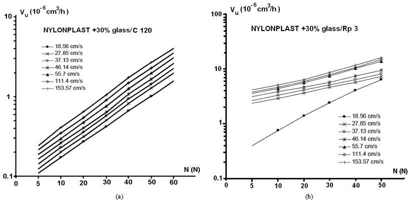 | Figure 4. The results of variation curves of the wear volume with normal loading and relative speed, for tested couples (a) Nyloplast AVE Polyamide + 30% glass fibres/ C120 steel and (b) Nyloplast AVE Polyamide + 30% glass fibres/ Rp 3 steel. Measurement errors were ±1.5 % |
Furthermore, the comparative evaluation of differentThus, using relations (12) and (13) the variation curves of the "comparative wear coefficients" (as volume and depth), K (cm3 / cm) and K* (mm / cm) are obtained. These master-curves are plotted in Fig. 5 and Fig. 6 representing the two tested and taken into discussion couples, for different normal loading values.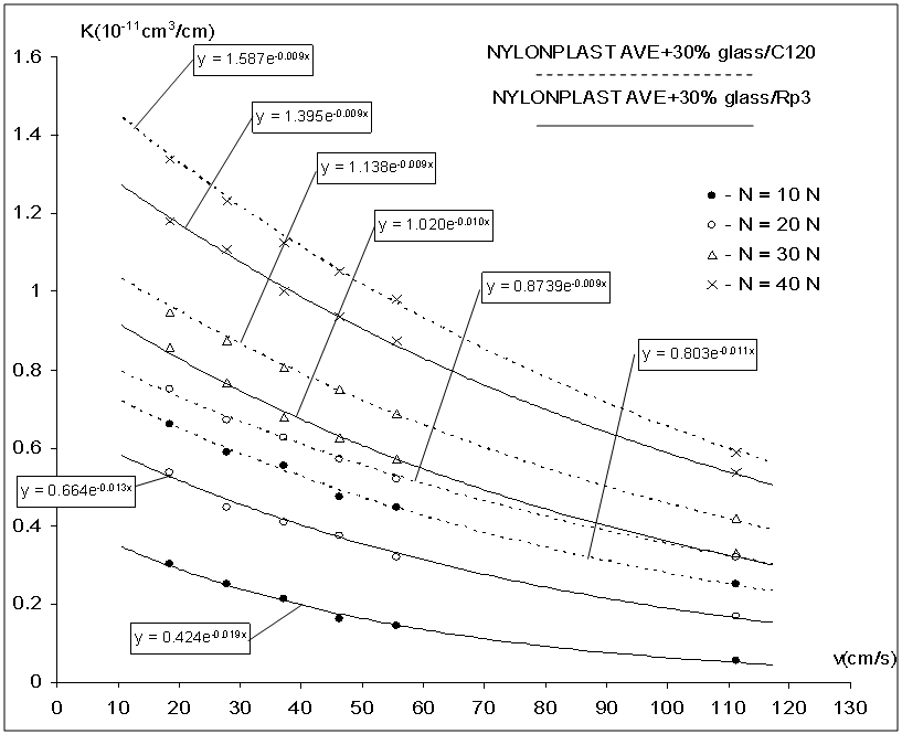 | Figure 5. The variation curves of the volumetric comparative wear coefficients K (cm3 / cm) |
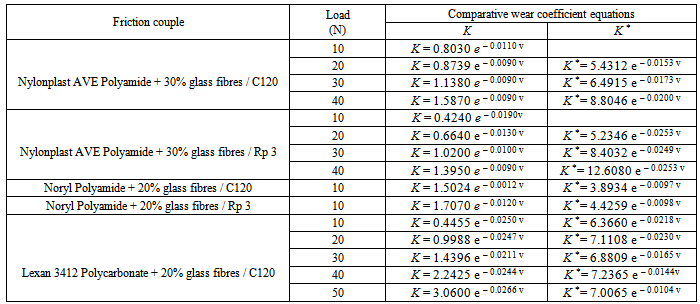
In Table 2 are listed the equations for the comparative wear coefficients (the volumetric and the depth ones).Table 2. The variation curve of comparative wear coefficient
 |
| |
|
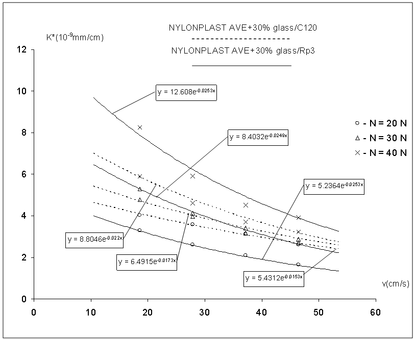 | Figure 6. The variation curves of the linear comparative wear coefficients K*(mm / cm) |
3.2. Microscopic Inspection
While measuring the wear traces widths with the help of optical microscopy, microphotographs are also taken, in order to identify the plastic material’s transfer and the metallic surfaces’ wear mechanisms. These microphotographs prove that the wear mechanisms vary from one couple to another, due to surfaces’ nature: metallic and composite plastic material, especially their hardness (59 HRC for C120 hardened steel and 62 HRC for Rp3 hardened steel), the glass fibres content, 30% and 20%, the composite plastic materials’ elasto-plastic characteristics while in contact with metallic surfaces. Considering the same loading conditions, the two couples to which is made reference have a different behaviour. On C120 steel sample (Fig. 7), at a normal load of 20 N and a contact temperature of 150℃, there are plastic material transfer bridges, crossing on the wear traces (Fig. 7a), as well as the glass-fibres torn from the polymer matrix. 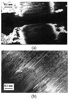 | Figure 7. Wear and plastic material transfer on C120 steel surface, following the friction with Nylonplast AVE polyamide reinforced with 30% fine glass fibres (a), in experimental conditions: v = 27,85 cm/s; N =20 N; T = 150 0C; t = 60 min and (b) in experimental conditions v = 27.85 cm/s; N =30 N; T = 175 0C; t = 60 min |
Considering the same mechanical stress conditions (load and relative speed), the microscopic inspection of the Rp3 steel samples, while in friction contact, with the same composite plastic material, reveals a less pronounced plastic material transfer through adherence onto the metallic surface, visible on the left side in Figs 8 (a) and 8 (b). If the test duration is double (120 min), practically there is no plastic material transfer as one can see in Fig 8 (c).It is considered that due to high registered contact temperature (237 0C) the transfer takes place for sure, but the transferred material is subsequently removed through friction from the contact area, under the form of wear particles following the glass fibres abrasive action. After this stage, the abrasive wear due to glass fibres becomes predominant. It is possible that the less pronounced plastic materialtransfer emphasized on the Rp3 steel surfaces to be due to this steel’s chemical composition and structure.| Table 3. The range of mean wear’s rate values for the tested friction couples |
| | Friction couple | Volumetric wear rate ( 10-6 cm3/h) | Linear wear rate (10-4 mm/h) | | v = (18.56 - 46.41) cm/s; N = 10 – 50 N | | Polyamide + 30% glass fibres/ C120 | 0.139 – 1.621 | 0.965 – 8.549 | | Polyamide + 30% glass fibres / Rp 3 | 0.214 – 1.369 | 2.382 – 6.004 | | Polycarbonate + 20% glass fibres / C120 | 0.244 – 1.309 | 3.592 – 6.366 | | v = (46.41 - 111.4) cm/s | | Polyamide + 20% glass fibres / C120 | 0.440 – 2.578 | 3,269 – 6.794 | | Polyamide + 20% glass fibres / Rp 3 | 0.473 – 2.549 | 3.792 – 6.627 |
|
|
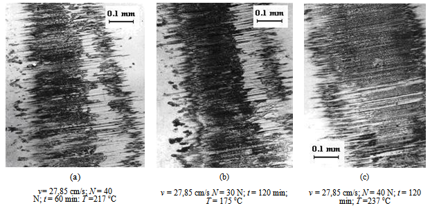 | Figure 8. Wear and plastic material transfer on Rp3 steel surface, following the friction with Nylonplast AVE polyamide reinforced with 30% short glass fibres |
We detect the same findings in the case of Noryl polyamide +20% glass fibres in friction on the same steels, but to a lesser scale. In the case of Lexan 3412 polycarbonate reinforced with 20% glass fibres friction onto the same metallic surfaces and considering the same stress conditions, generally speaking there is no plastic material transfer – Figs. 9 (a) and 9 (b)The transfer appears only if the load reaches 40 N, which corresponds to a contact pressure of 3449.7 MPa, and when the contact temperature reaches 251℃ - Fig. 9 (c). We do consider that probably the polycarbonate has a lesser transfer capacity than the polyamide.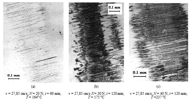 | Figure 9. Wear and plastic material transfer on Rp3 steel surface, following the friction with Nylonplast AVE polyamide reinforced with 30% short glass fibres |
4. Disscusion
The wear’s rate values, considering the used experimental conditions, cover a large range. For greater clarity, they are presented in Table 3.Comparing the metallic element’s wear rates values at v = 46.41 cm/s and N = 40 N, it results that the polyamide reinforced with 30% glass fibres induces to the C120 steel a wear of approximately 1.110 times more higher than to the Rp3 steel. It is estimated that this phenomenon is due to Rp3 samples’ higher hardness (62 HRC), in comparison to those from C120 (59 HRC).Normal loads and corresponding contact pressures for the linear friction contact used during this research, lead to very high contact temperatures (180-240℃) according to the applied normal load and relative sliding speed (see also Fig. 8a). In several cases they exceed the polymer’s melting temperature, thus being transferred on the metallic surface together with glass fibres fragments. Part of the glass fibres is smashed and still produced a predominant abrasive wear of the metallic sample’s contact area, while another part is pushed out on the contact’s exit edge, together with a multitude of ejected glass fibres. It is noticed that only in the case of the friction couple Nyloplast AVE Polyamide + 30% glass fibres / C120 steel, there is a large plastic material transfer onto the metallic surface, which justifies the assertion that the transfer through adhesion depends on the nature and characteristics of the contact materials.From a qualitative point of view, obviously there is the fact that initially the wear process manifests itself as a wear through adherence and polymer transfer onto the metallic surface, which subsequently transforms itself into a process of abrasive wear, which leads to the plastic material removal clung onto the contact area. In what the friction couples are concerned – also see Fig. 8a.The process’ intensity depends on the fibres’ content. The larger it is, the higher the intensity is. Metallic surface mechanical properties (especially the hardness), has a distinct influence over the plastic material transfer and metallic surface wear.
5. Conclusions
The diagrams’ analysis plotted in Figs. 5 and 6 allows to establish the variation equations for the comparative volumetric wear coefficient K and for the comparative depth wear coefficient K*, for steel in linear contact, while in friction with glass reinforced thermoplastics.The equations listed in Table 2 for the comparative wear coefficients (the volumetric and the depth ones) show that the variation is not a linear one, these coefficients evolving exponentially. The decrease of the K* coefficient with the increase of relative speed is faster than the decrease of the K coefficient. It is considered that this effect is due to the fact that the thermoplastic material deforms under load which means that for Timken type couples the increase of the wear imprint width is more effective than that of the depth of the wear imprint. From the diagrams plotted here, one can notice that the values of wear coefficients for the metallic component of the couple glass reinforced thermoplastic/steel are in the domain (10−11 ÷ 10−12) cm3/cm and respectively 10−9 mm/cm. The comparative wear coefficients and their master - curves vs. relative speed have a special importance from the practical point of view. Based on these findings we can establish an optimal couple of materials from the design phase.
ACKNOWLEDGEMENTS
The authors would like to thank the Romanian Academy for its material and technical support offered in order to achieve these researches.
References
| [1] | F.P. Bowden, D. Tabor The Friction and Lubrication of Solids, part I-II, Clarendon Press,Oxford,1964. |
| [2] | B. J. Briscoe, in: Friction and Wear of Polymer Composites, Ed. F. Klaus (Elsevier, Amsterdam, 1986), p. 25. |
| [3] | K. L. Johnson, K. Kendall and A. D. Roberts, Surface Energyand the Contact of Elastic Solids. Proc. Roy. Soc. A324, 301 (1971). |
| [4] | K. L. Johnson, Contacts Mechanics, (Cambridge University Press, Cambridge, 1987). |
| [5] | B. V. Deryagin, V. M. Muller and Yu. P. Toporov. Adhesive Contact Deformation of a Single Microelastic Sphere. J. Colloid Interface Sci., 53, 314 (1975). |
| [6] | K. L. Jonson and J. A. Greenwood. An Adhesion Map for the Contact of Elastic Spheres J. Colloid Interf. Sci., 192, 326 (1997). |
| [7] | D. Maugis, Adhesion of spheres: The JKR – DMT transition using a Dugdale model. J. Colloid Interf. Sci., 150, 243 (1992). |
| [8] | I. V. Kragelskii, Friction and Wear (Pergamon Press, Elms ford, 1982). |
| [9] | N. K. Myshkin, A. V. Kovalev. Adhesion and Friction of Polymers, in PolymerTribology. Imperial College Press, London, 2009. |
| [10] | V. E. Starzhynsky, A. M. Farberov, S. S. Pesetskii, S. A. Osipenko and V. A. Braginsky, Precision Plastic Parts and Their Production Technology, (Nauka I Tekhnika, Minsk, 1992) (in Russian). |
| [11] | B. J. Briscoe, Wear of polymers: an essay on fundamental aspects. Tribology Int., 14, 231, (1998). |
| [12] | G. Jintang, Tribochemical effects in formation of polymer transfer film. Wear, 245, 100 (2000). |
| [13] | H. Unal, U. Sen and A. Mimaroglu, Friction and wear behavior of unfilled engineering thermoplastics. Tribol. Int., 37, 727 (2004). |
| [14] | H. Unal and A. Mimaroglu, Sliding friction and wear behaviour of polytetrafluoroethylene and its composites under dry conditions. Mater. Des., 24 (2003), 239–245 Mater. Des., 24, 183 (2003). |
| [15] | Y. K. Chen, O. P. Modi, A. S. Mhay, A. Chrysanthou and J. M. O’Sullivan, The effect of different metallic counterface materials and different surface treatments on the wear and friction of polyamide 66 and its composite in rolling–sliding contact. Wear, 255, 714 (2003). |
| [16] | C. J. Schwartz and S. Bahadur, The role of filler deform ability filler–polymer bonding, and counterface material on the tribological behavior of polyphenylene sulfide (PPS). Wear, 251, 1532 (2001). |
| [17] | Y. M. Xu and B. G. Mellor, The effect of fillers on the wear resistance of thermoplastic polymeric coatings. Wear, 251, 1522 (2001). |
| [18] | B. J. Briscoe, L, Fiori, and E. Pelillo, Nano-indentation of polymeric Surfaces. J. Phys. D: Appl. Phys., 31, 2395 (1998). |
| [19] | H. Shulga, A. Kovalev, N. Myshkin, and V. V. Tsukruk, Some aspects of AFM nanomechanical probing of surface polymer films. European Polymer Journal, 40, 949 (2004). |
| [20] | A. Kovalev, H. Shulga, M. Lemieux, N. Myshkin, and V. V. Tsukruk, Nano-mechanical probing of layered nanoscale polymer films with atomic force microscopy. J. Mater. Res., 19, 716 (2004). |
| [21] | G. M. Bartenev and V. V. Lavrentev, Friction and Wear of Polymers, (Elsevier, Amsterdam, 1981). |
| [22] | L. Capitanu, A. Iarovici, J. Onisoru – On polyamide and polycarbonate materials behaviour under dry friction, The Annals of University “Dunarea de jos” Galati, fascicle VIII, Tribology, 2003, ISSN 1221-4590 |
 Abstract
 Reference
 Full-Text PDF
 Full-text HTML