Djillali Beida Maamar1, R. Zenasni1, A. Hebbar1, Jaime Vina Olay2
1Mechanical Department, University of Mostaganem, Laboratory LMNPM,BP 882, RP, 27000, Mostaganem, Algeria
2Department of Material Sciences, University of Oviedo, 33204, Gijon, Spain
Correspondence to: R. Zenasni, Mechanical Department, University of Mostaganem, Laboratory LMNPM,BP 882, RP, 27000, Mostaganem, Algeria.
| Email: |  |
Copyright © 2012 Scientific & Academic Publishing. All Rights Reserved.
Abstract
In this paper, the low velocity impact behavior of a composite material was investigated using the LS DYNA a finite element package. In order to investigate the damage produced by different impactors, three shape impactors were chosen (ball, cylinder, and truncated cone). The impactors impact the plate with a velocity of 6m/s. The composite was a carbon fiber/epoxy of sequence stacking[45/0/-45/90]s. All the impactors dropped the plate at the center. In order to study the effect of the inclination of the laminated plate, three different inclination angles were chosen (30, 45 and 60°). The loads, the impact energy, the displacements and the Von Mises stresses were computed and represented in a different graphs en function of the time of the impact. The truncated cone and a cylinder provide a higher impact forces and a displacements (great damaged zone). In the case of an angle of 30°, the ball produced a higher displacement and impact energy.
Keywords:
Composite, Finite Element, Impactor Shapes, Laminate Inclination, Stacking, Mat54, Lsdyna
Cite this paper: Djillali Beida Maamar, R. Zenasni, A. Hebbar, Jaime Vina Olay, Finite Element Modeling of Composite Materials Subjected to the Low Velocity Impact Damage, American Journal of Materials Science, Vol. 3 No. 1, 2013, pp. 1-7. doi: 10.5923/j.materials.20130301.01.
1. Introduction
The fibrous composites are being increasingly used in load bearing structures due to number of advantages over conventional materials: high specific strength and stiffness, good fatigue performance and corrosion resistance. A serious obstacle to more widespread use is their sensitivity to impact and static loads in the thickness direction. As composites have demonstrated to be very venerable to out of plane impact, which cause barely visible impact damage (BVID) reportedly contributes up to 60% loss in structures’ compressive strength and major reason of catastrophic failures. The energy absorbed during impact is mainly dissipated by a combination of matrix damage, fibre fracture and fibre-matrix de-bonding, which leads to significant reductions in the load carrying capabilities. In ballistic impacts the damage is localized and clearly visible by external inspection, while low velocity impact involves long contact time between impactor and target, which produces global structure deformation with undetected internal damage at points far from the contact region. For such reasons the low velocity impact are often simulated by simple static indentation-flexure tests, neglecting the influence of dynamic effects. It is also suggested the complete model to take into account the full dynamic behavior of the laminates. Abrate and al[1] have investigated the delamination of two laminated composite graphite/PEEK and graphite/BMI under low velocity impact. The range number of layers varies from 9 to 95 plies. The obtained result shown a higher delamination threshold load and higher damage resistance. The resulting damage is not normally visible on the specimen surface nor is easily detected and grows rapidly during normal service cycles, thus reducing the strength and operational life. The area has been under active research for a quite some time. Some of the relevant articles addressing this issue found in the literature are presented below. The strategy of reducing the stiffness of damaged plies to a certain fraction without considering the degree of damage was used by some investigators[2, 3]. Other researchers applied damage theory of continuum mechanics to address the internal damage. They initiated the stress-strain relation for the actual damaged by introducing a fourth-order damage operator to transform the compliance matrix according to the damage states. Based on this work, several investigations were conducted in the subjects such as tension of composite laminates with holes and high velocity impact of composite laminates[4-7]. They adopted the simple assumption that when damage occurs, the mechanical properties would reduce to certain levels. The impact induced de-lamination another important damage mode was combined because the level of impact energy to initiate de-lamination is low and the post-impact compressive strength reduces dramatically. New techniques used in[8] to model the laminate as a stack of elements tied by contact interface conditions, allows the inter-laminar layers to model and predict strength reduction. Because of the complex nature, a simple and effective criterion for the BVID prediction and damage/delamination initiation is still lacking. The stability of simulation was another important issue to be considered, when changes of material properties were taken into account. Cantwell and Morton proposed a pine tree damage pattern and a reversed pine tree damage pattern for the impact-induced matrix cracks in thick and thin thickness laminated composites, respectively[9]. Freitas proposed a pine tree damage pattern with vertical matrix cracks on the bottom layer[10]. Since 1980s, many researchers have analytically and experimentally investigated the low velocity impact behaviour of composite laminated structures. Most composite structures will be under some level of stress when impacted. For example, the upper skin of the main wing of the aircraft will be mainly under in-plane compressive load during flight and the lower one will be under in-plane tensile load. So, foreign objects like hail and debris in the runway shall give an impact to 638. Umar Farooq and Karl Gregory[11] have studied a composite laminated structure under in-plane load. However, a few studies on the impact behaviour of the composite laminates under in-plane load have been published. In 1985, Chen and Sun[13] have developed a finite element program to analyze the impact response of the composite laminate under biaxial in-plane load. Using the finite element program they solved for three cases of in-plane load, tension/tension load of 3 times of critical buckling load of the plate, compression/compression load of 75% of it, and no initial in-plane load. The impact condition is the case that the mass of the impactor is very small and the impact velocity is very high. They concluded that the initial tensile in-plane load tends to intensify the contact force while reducing the contact time, and an opposite conclusion is obtained for an initial compressive in-plane load. After their study, it is very rare to find another analytical result on the impact behaviour of the composite laminates under in-plane load. Introduction Wu and Chang[14] have conducted a transient dynamic finite element analysis for studying the response of laminated composite plates subjected to transverse impact loading by a foreign object. They have calculated displacements, the transient stress and the strain distributions through the thickness of laminate during the impact event. Gaurav Nilakantan and al.[15] have used the multiscale modeling techniques to analyze the impact damage of woven fabric by the finite element. On the other hand, Manish Khandelwal and al[16] have studied the delamination initiation in FRP under low velocity impact. The analysis was conducted using 3D finite element. The composite material studied were Graphite/epoxy and hybrid Glass-Graphite Epoxy.
2. Finite Element Modeling
2.1. Composite Laminates
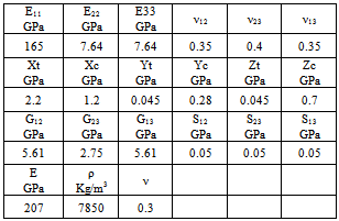
The studied composite material was a TM800s/M21; it was made of a matrix epoxy reinforced with carbon fiber of stacking sequence[45/0/-45/90]s. The composite fiber volume fraction was 33%. All the composite specimens were of the same dimensions: 120x60x2.5 mm. The ply thickness was 0.25mm. The specimens were centrally loaded. The table 1 presents the mechanical properties of the composite material and the impactors. The impactors dropped the plate at the center. The Fig.1, present the fiber orientation in the system axis. All the sides of the laminated plate were fixed. The material of the impactors was ordinary steel. The impact problem can be described as shown in Fig.1. An impactor of a mass m and shape drops on the center of the laminated plate with a velocity V. Table 1. Mechanical properties of the composite material and the impactor
 |
| |
|
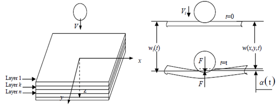 | Figure 1. A basic model for impact damage |
2.2. Numerical Modeling
The Ls dyna model Mat54 was employed to study the impact behavior of the plate and the model Mat_20 for the impactors. The plate and the impactor were meshed using four quadratic isoparametric shell element. 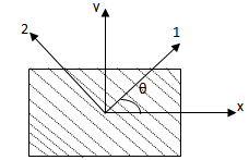 | Figure 2. Local and global axis |
Fig.3, show the distribution of the bending moments and the shear forces through the composite plate.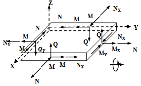 | Figure 3. Bending moments and shear forces |
Where:Nx, Ny,Nxy: In plane loadsMx,My,Mxy: Bending moments about x-y axisQx,Qy: Shear forcesThe stresses were calculated by the equation (1). The coefficient of stiffness’s in out of plane, of the laminated plate where calculated using the equation (1). | (1) |
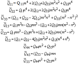 Where:
 E1, E2: Elastic modulus in axis 1 and 2G12, G13, G23: Shear modulusWhere:
 In the case of the in plane stresses, eq.(1) become (2):
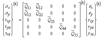 | (2) |
2.3. Effect of the Impactor Shapes
Three impactors of the same material and different shapes were used in order to impact the laminated plate (cylinder, ball, truncated cone). The table 2, present the geometrical properties of the three impactors. The impact velocity used was 6m/s for all the impactors. The table 3, shown the number of elements and nodes used in order to mesh the impactors and the composite plate| Table 2. Geometrical properties of the impactors |
| | Impactors geometrical properties | | Ball: Diameter =12mm | | Cylinder: Diameter=8mm, height= 18mm | | Truncated cone: Diameter1=5mm, Diameter2=14mm,height=19.74mm |
|
|
| Table 3. Elements and nodes used in numerical modeling |
| | | Elements | Nodes | | Laminated plate | 115200 | 115921 | | Ball | 96768 | 98617 | | Cylinder | 166375 | 172256 | | Truncated cone | 579726 | 594648 |
|
|
Figure 4, present the displacement variations en function of the impact time for the three impactors. The displacement curves present the same pace, the maximum central displacement was obtained by a truncated cone about of 0.5549 mm for an impact time about 0.2ms, the ball give a value of displacement about 0.5356 mm for impact time about 0.19ms, while the cylinder provide a value about 0.5242 mm for the impact time about 0.18ms.The impact forces were shown in figure 5 en function of the impact time. The cylinder and a truncated cone present more or less the same curve forms with a slight variation. The impact force obtained was about 0.0045KN for a time of impact of 0.22ms. In the case of a ball, the load curve show a maximum and a minimum values. The maximum load was about 0.035 KN for the impact time of 0.23ms.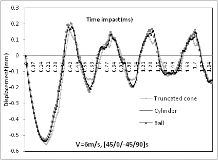 | Figure 4. Displacement en function of time |
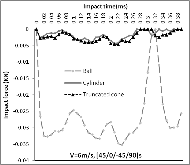 | Figure 5. Impact load en function of time |
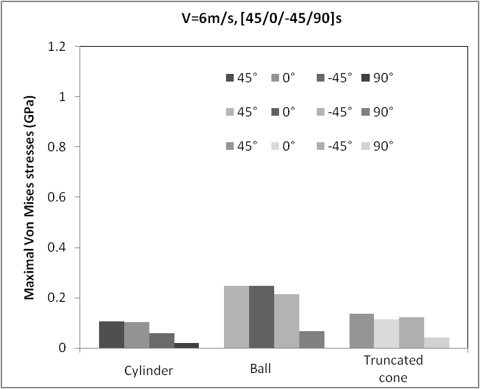 | Figure 6. Von Mises stresses |
In figure 6, we present the maximal Von Mises stresses in each ply of the composite for the three impactors. The ball provides the maximum stresses about 0.247GPa in plies of orientations 45° and 0°. The cylinder present a minimum values of stresses about 0.11GPa for ply 45° and 0°), while in ply 90° the stresses value was 0.020 GPa. The truncated cone, shown a value of stresses about 0.13GPa for layer 45° and 0.12 GPa for layer -45°.The impact energy curves were shown in figure 7, the maximum energy value was about 0.1166 J for impact time of 0.18ms for the three impactors. 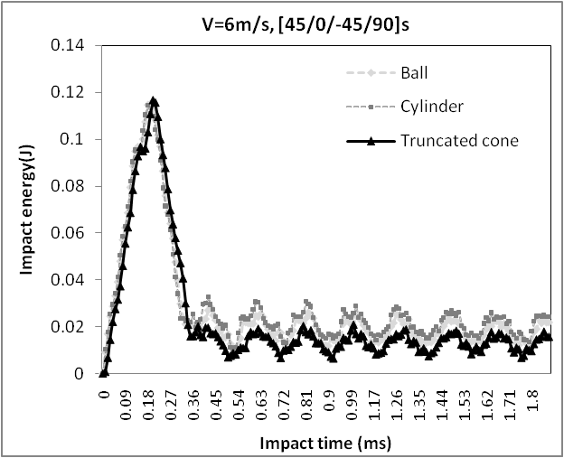 | Figure 7. Impact energy en function of time |
2.4. Effect of the Inclined Laminated Plate
The laminated plate was inclined by an angle with respect to the horizontal axis, see figure 8. Three different angles were chosen (30°, 45° and 60°). The impactors dropped the inclined plate at the center with a velocity of 6m/s.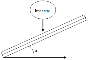 | Figure 8. Inclined laminate |
The central displacement for the three angles was presented in figure 9. The inclination of 30° gives a maximum displacement of 0.493mm for a time of the impact about 0.2ms for the ball impactor. In the case of the cylinder, the maximal displacement was 0.392mm, while for the truncated cone the displacement obtained 0.314mm for the time of the impact about 0.2ms. In the case of the inclination of 45°, the ball impactor provides a maximal displacement about 0.32mm for the time of the time of impact of 0.22ms. The cylinder gives a displacement about 0.16mm; at the end the displacement obtained by the truncated cone was 0.161mm. The inclination of 60° gives a displacement about 0.164mm for the ball (time of the impact about 0.22ms) and a maximal value of 0.202 mm for the cylinder. The minimal displacement was 0.06&mm for the truncated cone (time of the impact about 0.11ms). | Figure 9. Displacement variations |
Figure 10, present the variation of the impact load en function of the time of the impact for the three plate inclinations. The inclination 30° gives a maximal impact load about 0.023KN for the time of the impact of 0.05ms in the case of the cylinder impactor. The minimal impact load was obtained by the ball impactor (0.014KN which correspond for the time of the impact about 0.012ms). In the case of the inclination of 45°, the ball provides a maximal load about 0.013KN corresponding for the time of the impact 0.03ms. The truncated cone, gives a minimal impact load 0.0096KN, while for the cylinder, the load was more or less equal to the ball impactor. 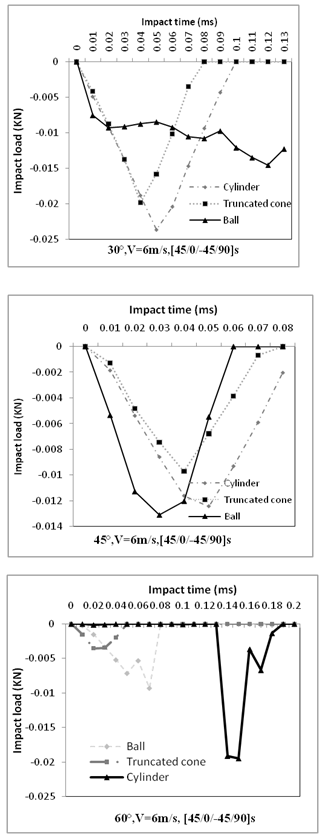 | Figure 10. Impact load en function of time |
The inclination 60° gives a maximal displacement about 0.019KN corresponding for the time of the impact 0.15ms in the case of the cylinder. The truncated cone provides a minimal load (0.0034KN which correspond to 0.03ms).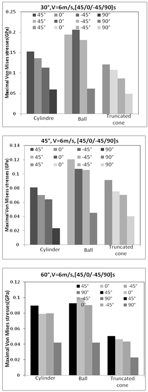 | Figure 11. Maximal Von Mises stresses |
The maximal Von Mises stresses were shown in figure 11 for the different inclinations, ply orientations, and the impactors. In the inclination of 30°, the ball provides the maximal stresses at the ply 0° about 0.2GPa. The cylinder gives a value of Von Mises stresses about 0.15GPa for the ply of orientation 45°. The truncated cone provides a minimal value of 0.048GPa at the ply of orientation 90°. The inclination 45°, the maximal value of the stress was obtained by the ball impactor at the ply 45° which correspond for a value about 0.12GPa. We obtain a minimal stress in the case of the cylinder (0.023GPa for the ply 90°). The inclination 60°, the maximal stress was about 0.099 GPa for the ply 0° which was provided by the ball impactor. The truncated cone gives a value of minimal stresses (0.023GPa at the ply 90°).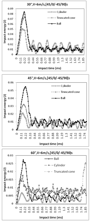 | Figure 12. Impact energy en function of time |
Figure 12, present the variation of the impact energy for the three laminate inclinations. The inclination 30°, gives a maximal impact energy about 0.084J corresponding for the time of the impact about 0.22ms in the case of the ball impactor, the minimal energy was obtained by a truncated cone (0.05J which correspond for 0.16ms). For the inclination of 45°, the maximal energy was 0.052J which correspond to 0.19ms in the case of the ball impactor. The cylinder provides a value of the impact energy about 0.032J for a time of 0.17ms. At the end the truncated cone gives minimal impact energy about 0.021J. In the case of angle of 60°, the maximal energy value was obtained by the ball impactor (0.027J which correspond for 0.18ms). The truncated cone gives a value of the energy of 0.0061J for the time of the impact about 0.12ms.
3. Conclusions
The impact damage mechanism in a laminate constitutes a complex process. It’s a combination of matrix cracking, buckling, fiber breaking, delamination its usually all interact with each other. The paper presents the numerical modeling of a low velocity impact damage of a composite material using the package Lsdyna. Three shapes of impactor were used in the analysis (Ball, truncated cone and cylinder). All the impactors dropped the laminate plate at the center with a velocity of 6m/s. The composite material used was a carbon/epoxy of sequence stacking[45/0/-45/90]s. The impact displacements, loads, energy impact and the maximal Von Mises stresses were reported in graphs en function of the impact time. The inclination of the laminate was taken account, three angle inclinations were chosen (30°,45° and 60°). In the case of an angle of 30°, the maximal displacement was obtained by the ball impactor.
ACKNOWLEDGMENTS
I would like to thank the company Livermore Software Technology Corporation for the LS DYNA full evaluation package.
References
| [1] | S. Abrate, Modeling of impacts on composite structures, Compos Struct 51 (2) (2001), pp. 129– 138. |
| [2] | Iber, W.; ”Failure Mechanics in Low-Velocity Impacts on Thin Composite Plates, “ NASA Technical Paper 2152, 1983. |
| [3] | Sjoblom, P.O.; Harness, T.J.; “On low Velocity Impact Testing of Composite Materials, “ Journal of Composite materials, Vol. 22, pp. 30-52, January 1988. |
| [4] | Waedle, B. L.; ana Lagace, P.A.; “On the Use of Dent Depth as an Impact Metric for Thin Composite Structures, “Journal of Reinforced Plastics and Composites, Vol. 16, No. 12, pp. 1093-1110, 1997. |
| [5] | Kwon, Y.S, and Sankar, B. V.: “Indentation-Flexure and Low-Velocity Impact Damage in Graphite Epoxy Laminates, “Journal; of Composites Technology and Research, Vol. 15, No. 2, pp. 101-111. |
| [6] | Swanson, S.R.: “Limits of Quasi-Static Solutions in Impact of Composite Structures,” Composite Engineering, Vol. 2, No. 4, pp.261-267, 1992. |
| [7] | Husman, G.E., et al. 1979. “Residual strength characterization of laminated composites subjected to impact loading, “ ASTM STP 568: 92-113. |
| [8] | Roten, A. 1988. “Residual flexural strength of FRP composite specimens subjected to transverse impact loading” SAMPE J. 24(2): 19-25. |
| [9] | S. Abrate, Impact on laminated composite materials, Appl Mech Rev 44 (4) (1991), pp. 155– 190. |
| [10] | M. de Freitas, A. Silva and L. Reis, Numerical evaluation of failure mechanisms on composite specimens subjected to impact loading. Composites: Part B 31 (2000), pp. 199–207. |
| [11] | Umar Farrok, Finite Element Simulation of Low Velocity Impact Damage Morphology in Quasi_Isotropic Composite Panels Under Variable Shape Impactors, European Journal of Scientific Research ISSN 1450-216X Vol.25 No.4 (2009), pp.636-648, Euro-Journals Publishing, Inc. 2009. |
| [12] | R. Tiberkak, M. Bachene, S. Rechak and B. Necib, Damage prediction in composite plates subjected to low velocity impact, Compos Struct 83 (2008), pp. 73–82. |
| [13] | J.K. Chen and C.T. Sun, Dynamic large deflection response of composite laminates subjected to impact, Compos Struct 4 (1985), pp. 59–73. |
| [14] | H.Y.T. Wu and F.K. Chang, Transient dynamic analysis of laminated composite plates subjected to transverse impact, Comput Struct 31 (1989), pp. 453–466. |
| [15] | Gaurav Nilakantan and al. On the finite element analysis of woven fabric impact using multiscale modeling techniques, International Journal of solid and Structures 47 (2010) 2300-2315. |
| [16] | Manish Khandelwal, D.Chakraborty and U S Dixit, Delamination initiation in FRP laminated composites under low velocity impact, Proceeding of the International conference on Mechanical Engineering 2003, Dhaka, Bangladesh. |
 Abstract
 Reference
 Full-Text PDF
 Full-text HTML