-
Paper Information
- Next Paper
- Paper Submission
-
Journal Information
- About This Journal
- Editorial Board
- Current Issue
- Archive
- Author Guidelines
- Contact Us
American Journal of Materials Science
p-ISSN: 2162-9382 e-ISSN: 2162-8424
2012; 2(6): 165-170
doi: 10.5923/j.materials.20120206.01
Material Processing Technology for Soft Ferrites Manufacturing
 Abstract
 Reference
 Full-Text PDF
 Full-Text HTML
Deepak Bhalla1, DK. Singh2, Swati Singh1, Dipti Seth3
1ACME College of Engineering, Muradnagar, Ghaziabad, India
2Mechanical Engg Deptt, MMM Engineering College, Gorakhpur, India
3Deptt of Applied Sciences, Raj Kumar Goel Engineering College Pilkhuwa, Ghaziabad, India
Correspondence to: Deepak Bhalla, ACME College of Engineering, Muradnagar, Ghaziabad, India.
| Email: |  |
Copyright © 2012 Scientific & Academic Publishing. All Rights Reserved.
In this paper efforts have been made to explain the manufacturing method of Manganese-Zinc (Mn-Zn) soft ferrites in detail along with its uses and applications. The same method is applicable to Nickel-Zinc (Ni-Zn) and Lithium Titanium (Li-Ti or Microwave) ferrites also. A process flow chart is shown. The manufacturing steps like-mixing of powders, calcination of powder, grinding of powder, granules making, pressing of components, sintering in tunnel kiln or box furnace and machining on rotary table grinding machine, have been explained. Effect of atmosphere (oxygen), when the components are sintered at high temperature, is discussed. The temperature profiles of muffle furnace and tunnel kilns have also been discussed. The variation in temperature within the muffle furnace (900×900×800 mm) has been studied with the help of a sliding thermocouple. Temperature gradient within the furnace volume has been plotted on graph. A mathematical relation has been found using curve fitting equation. Actual and mathematical results have been compared.
Keywords: Soft Ferrites, Processing, Temperature, Furnace, Sintering
Cite this paper: Deepak Bhalla, DK. Singh, Swati Singh, Dipti Seth, "Material Processing Technology for Soft Ferrites Manufacturing", American Journal of Materials Science, Vol. 2 No. 6, 2012, pp. 165-170. doi: 10.5923/j.materials.20120206.01.
Article Outline
1. Introduction
- Ferrites are dense homogeneous ceramic materials used, as a core, in the transformers, for electronics devices. Ferrite cores are also used as inductors and electromagnets in electro-mechanical and electronic industries. The operating frequency range of these transformers may vary from 100 Hz to 2.5 Giga Hz, or even more. These are rigid and brittle in nature. These are expressed by the molecular formula MFe2O4 (where M is an Oxide of Divalent Metal). When Ferrite contains two or more metal ions in M Positing, then it is called mixed ferrite. Such as Manganese Zinc (Mn-Zn) & Nickel Zinc (NI-Zn).Ferrites have a paramount advantage of bearing better properties such as high electrical resistivity resulting in low eddy current losses, over a wide frequency range in comparison with other types of magnetic materials. Other characteristics are high permeability and temperature stability, low cost, low volume (occupies less space), high stability w.r.t. temperature, humidity & pressure. The intricate geometrical shapes are possible to for larger production.The color of Ferrites may be silver gray or black. The mechanical and electromagnetic properties of ferrites can be affected by operating process conditions such as raw material composition, temperature, sintering atmosphere,compacting pressure, type of grinding and machining etc. There are two types of ferrites- (i) Soft Ferrites and (ii) Hard Ferrites (permanent magnets).A few soft ferrite components are shown below:
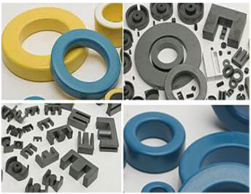 | Figure 1. Ferrite Components |
2. Experiments
- The following are the main steps involved in manufacturing of soft ferrite components:Powder mixing Pre sinteringWet grinding of powdersSpray drying Pressing of homogenous mixture to obtain desired shapeSintering in tunnel type furnaces (temp 1400℃)Machining of sintered product to obtain end product.A typical flow chart of soft ferrite manufacturing is shown below:
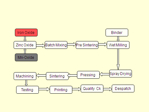 | Figure 2. Process steps of soft ferrite manufacturing |
2.1. Mixing of Powders
- In mixing operation, salts of metals (in the form of oxides or carbonates) are checked for purity (in ppm) by the chemical analysis. High purity raw materials are needed to manufacture ferrite cores, so that these yield good mechanical and magnetic properties.Wet mixing (Water used as a media) for 2 kg batch is done with following details:(i) Weight of dry powders (iron oxide, manganese di-oxide and zinc oxide) =2.0 kg.(ii) Weight of de-ionized water= 5 kg(iii) Mixing time= 8 HrsAfter 8 hrs. of mixing, the slurry is dried into oven at 150℃ for overnight which gives dry & mixed powder. Figure 3 shows the mixing method.
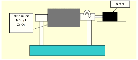 | Figure 3. Ball mill for wet (de-ionised water based) mixing of powders and grinding |
2.2. Calcination of Powders
- After mixing, the powder is calcined (pre-heated) at a temperature around 75% of final sintering temperature. Few manufacturers are converting powder into small pallets to save process loss during calcination. Calcination is a pre firing process in which the powder temperature is raised to approximately 940℃ (for a typical Mn-Zn ferrite composition) in air atmosphere. During calcination the carbonates are converted into oxides, the impurities get evaporated and the shrinkage at final product is reduced to 17 to 18% instead of 20 to 21%, this reduces the possibility of cracks formation during cooling of sintered product. A schematic diagrame of calcination is shown in Figure. 4, where a ratary kiln is being used. Powder is fed from one end through hopper and is being collected after passing through the kiln.
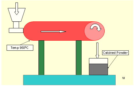 | Figure 4. Calcination (Pre-sintering) in rotary kiln |
2.3. Grinding
- Wet grinding is performed in the ball mill as shown in Figure. 3. This operation is similar to wet mixing with the only difference that the ball-mill running time is 20 to 24 hours, instead of 8 hrs, to ensure the particle size reduction to 2 to 16 µm. After wet grinding, the slurry is dried-up in the oven.Calcined (prefired) and sintered M-Zn ferrites could achieve the maximum density (4.95 g/cm3), and the average grain size was 8-10 μm. with pure ferrite phase. Flavin E.[3] stated that high frequency permeability is dependent on the particle size.
2.4. Granules Making
- From this fine, mixed and dried ferrite powder, granules are prepared by hand or by spray drier. For 200 kg batch granules are made using spray drier and for smaller batches granules are made manually.
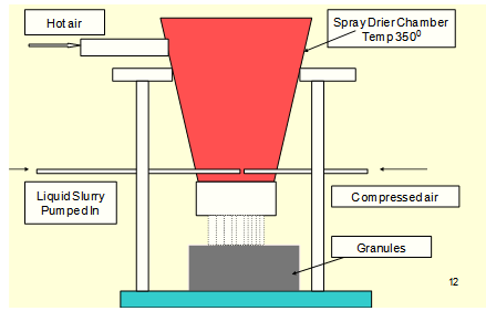 | Figure 5. Spray drying for preparing granules |
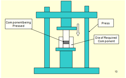 | Figure 6. Press for compacting powders |
2.5. Pressing
- The next step is forming of the component. Forming or pressing is done on mechanical, hydraulic or isostatic press. The capacity of press ranges from 2 tons to 100 tons depending upon cross section area of the component. The pressure is kept from 1 ton to 1.5 ton per cm square. During pressing the desired shape of component is obtained. The rods may be pressed by extrusion method also.Pressing in a closed die is done using simultaneous action of top and bottom punches in die cavity such that uniform density is obtained. With the help of press tool assemblies, very complex core shapes can be pressed. The height of green component can be adjusted by changing the die-fill. As per Dietmar Holz.[4] the homogeneity of the density profile along the compact, is related to the chance of crack development and product deformation during sintering this obviously means deterioration in its density and permeability.
2.6. Sintering
- This is very critical step in the manufacturing of ferrites. At this stage the product achieves its final magnetic and mechanical properties. Sintering of manganese-zinc ferrites needs control of time, temperature and atmosphere at the each phase of the sintering cycle. Sintering starts with a gradual heating from room temperature to approximately 800℃ as impurities, residual moisture, binders, and lubricants are burnt out of the product at this stage. The atmosphere at this stage of the sintering cycle is air.The temperature is further increased to the final sinter temperature of 1325 to 1375℃, depending upon the composition of material. While the temperature is increasing, a non oxidizing gas, nitrogen, is introduced into the kiln to reduce the oxygen content of the kiln atmosphere. During the cool-down cycle a reduction of oxygen pressure is very critical in obtaining high quality Mn-Zn ferrites. The sintering of nickel-zinc and lithium titanium, ferrites occurs at lower temperatures, in the range of 950-1250℃. This material can be sintered in an air atmosphere. During sintering the ferrite parts shrink (15 to 17%) to the final dimensions. The variation in mechanical dimensions is of the order of ±2% of the basic sizes of the part. Topfer J[5] mentioned that the properties of Mn Zn ferrites and the loss depend on the purity of raw materials, influence of the dopant and sintering process.The effect of Zn and Ti additions has a drastic change of the curie temperature with about 10–12℃ for each atomic percent of Zn and Ti introduced into the spinal lattice while the cooling speed changed the behavior of magnetic permeability with temperature around the curie point as discussed by Miclea C[6].
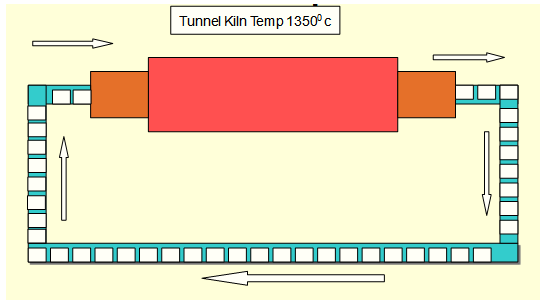 | Figure 7. Tunnel kiln for sintering ferrite components |
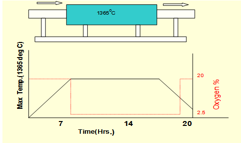 | Figure 8. Temperature and atmosphere profile |
2.7. Machining and Lapping
- Machining is done to obtain the specified dimensions by grinding these cores with a diamond wheel. This operation is optional. The ferrite cores are ground with, the help of diamond grinding wheels which are usually cup shaped. The machines used are vertical spindle rotary table grinding machines as shown in Figure. 9. Although the major magnetic properties are achieved during sintering and cannot be changed, the better surface finish at the mating surfaces yields better magnetic performance of ferrite cores. Thus lapping of mating surfaces is essential for proper control of flatness and degree of finish of the mating surface. The following types of grinding wheels are used for machining the ferrite cores:Silicon carbide grinding wheelDiamond-impregnated metal-bonded grinding wheelDiamond-impregnated resin-bonded grinding wheelResin and metal (resmet) bonded diamond-impregnated grinding wheelGalvanic bonded diamond grinding wheelCubic boron nitride (CBN) grinding wheelMostly water is used as a coolant. Cracks are avoided in the cores, with the application of coolants.
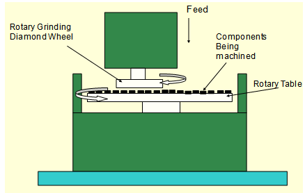 | Figure 9. Machining on rotary table grinding machine |
2.8. Quality Checks
- Physical inspection is done to ensure crack-free components. At the same time this is ensured that the components do not have buckling, which may appear during sintering or during machining. Then dimensions are checked as per drawing with the help of dial caliper, micrometer, height gauge or depth gauge etc. Electrical properties such as resistivity, permeability, AL value, B-H loop (hysteresis curve) parameters, saturation magnetization, curie temperature are checked.
3. Results and Discussion
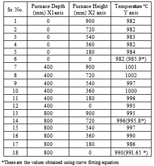
- Hard and soft ferrites play a dominant role in magnetic materials, and are produced in significant quantities. Although both material classes, Manganese Zinc and Nickel Zink are used in a variety of applications, the parameters for using the currently available material qualities do not correspond to those desired by system designers. As a result, research and development in both industry and institutes have undertaken great efforts to develop new classes of ferrite materials. After a short introduction into the properties of Mn-Zn ferrites and the loss determining contributions, the complex topics such as, the purity of the raw materials, influence of the dopant, and the sintering process are presented with respect to their effects on the soft ferrite properties.[8]Out of many process parameters the effect of temperature variation within muffle furnace has been studied and found that the maximum permissible variation in the temperature within the muffle furnace having volume 900×900×800 mm has been studied with the help of sliding thermocouple and the shrink ring as shown in Table 1. This was coming up to 20℃. This variation is responsible for rejection of the components in mechanical & magnetic properties.
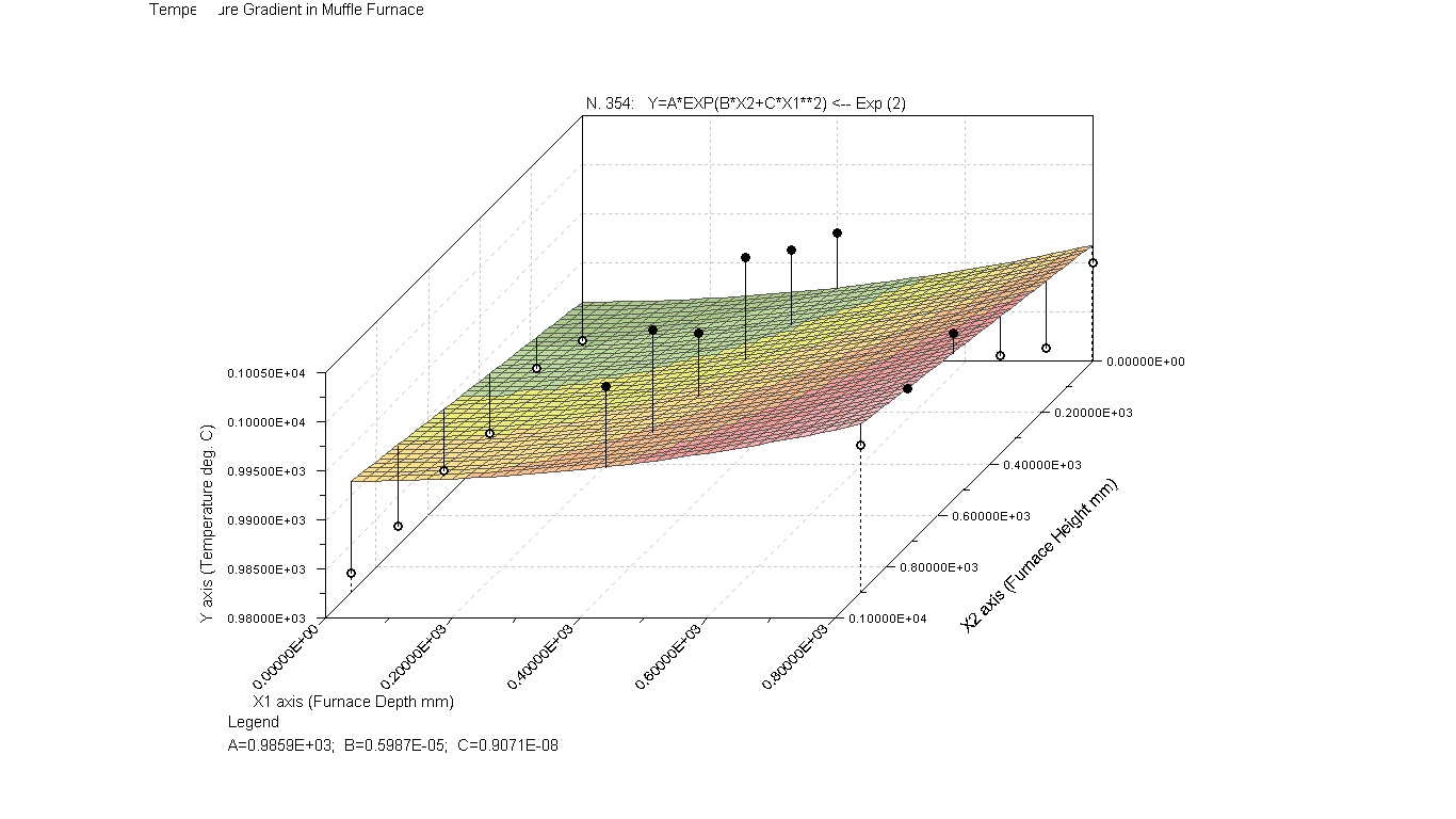 | Figure 10. Temperature gradient in muffle type (box) furnace |
|
4. Conclusions
- In modern electronics the ferrites are in huge demand. This is very essential for an electronic circuit design engineer to be familiar with the manufacturing techniques of these ferrites. The application fields are applied electronics, power conversion, communications, computers, instrumentation and high energy physics. The composition of raw materials, their originating source and process steps greatly affect the magnetic properties of these ferrites and its shapes. In order to select the correct material and shape, By understanding the above mentioned process and manufacturing details, a design engineer will keep in mind the limitations faced by a manufactures and the correct shape and size of the core will be chosen. These manufacturing details also useful for new entrepreneur to establish a soft ferrite manufacturing unit. Besides this is of immense use for the research scholars in field of applied electronics and exploring the new possible areas of research. This will improve the quality of existing ferrite manufactures also.The variation in the mechanical and magnetic properties of ferrite or similar ceramic components which have been sintered in kiln has ever been remained a problem. The actual temperature varies because the position of thermocouple (which reads the temperature) and the component position is different. To find a solution of this, the temperature gradient within the furnace volume, has been studied. This is of immense use because a mathematical equation has been fitted to predict and find the exact temperature at the particular point, within the furnace volume for precision sintering.