Esther T. Akinlabi , Stephen A. Akinlabi
Department of Mechanical Engineering Science, University Of Johannesburg, Auckland Park Kingsway Campus, P. O. Box 524, Auckland Park, Johannesburg, 2006, South Africa
Correspondence to: Esther T. Akinlabi , Department of Mechanical Engineering Science, University Of Johannesburg, Auckland Park Kingsway Campus, P. O. Box 524, Auckland Park, Johannesburg, 2006, South Africa.
| Email: |  |
Copyright © 2012 Scientific & Academic Publishing. All Rights Reserved.
Abstract
This paper reports the effect of heat input on the resulting properties of joints between aluminium and copper produced with the friction stir welding process. The welds were produced using three different shoulder diameter tools, viz: 15, 18 and 25 mm by varying the rotational speed between 600 and 1200 rpm and the traverse speed between 50 and 300 mm/min in order to vary the heat input to the welds. The microstructures, the grain sizes and the microhardness of the joint interfaces were characterised, and the electrical resistivities of the joints were also measured. The resulting microstructural characterization revealed that good metallurgical bonding was achieved at the joint interfaces of the welds produced; this is evident with the presence of interlayers of aluminium and copper observed in the stir zones of the welds. The grains at the interfacial regions were recrystallized leading to a sharp decrease in the grain sizes compared to the parent materials. Higher Vickers microhardness values were measured at the joint interfaces resulting from strain hardening and the presence of intermetallics. It was also observed that the electrical resistivities of the joints increased as the heat input to the welds increases.
Keywords:
Electrical Resistivity, Friction Stir Welding, Microhardness, Microstructure
Cite this paper:
Esther T. Akinlabi , Stephen A. Akinlabi , "Effect of Heat Input on the Properties of Dissimilar Friction Stir Welds of Aluminium and Copper", American Journal of Materials Science, Vol. 2 No. 5, 2012, pp. 147-152. doi: 10.5923/j.materials.20120205.03.
1. Introduction
Friction Stir Welding (FSW) is a solid–state joining technique invented and patented by The Welding Institute (TWI) in 1991 for butt and lap welding of ferrous and non–ferrous metals and plastics[1]. Since its invention, the process has been continually improved upon as its scope of application becomes expanded. FSW is a continuous process that involves plunging a portion of a specially shaped rotating tool between the abutting faces of a joint. The relative motion between the tool and the substrate generates frictional heat that creates a plasticised region around the immersed portion of the tool. In addition, the shoulder prevents the plasticised material from being expelled from the weld, therefore, the tool is moved relatively along the joint line, forcing the plasticised material to coalesce behind the tool to form a solid–phase joint[1]. Figure 1 illustrates the process definitions for the tool and work piece. The inserted picture also depicts the tool shoulder and the tool pin. The tool pin is sometimes referred to as the probe. The advancing side is on the right, where the tool rotation direction is the same as the tool travel direction (opposite the direction of metal flow), while the retreating side is on the left, where the tool rotation is opposite to the tool travel direction (parallel to the direction of the metal flow).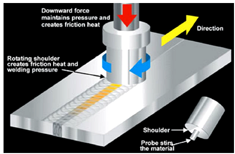 | Figure 1. Schematic diagram of the friction Stir Welding process[2] |
The tool serves three primary functions; the heating of the workpiece, the movement of material to produce the joint, and the containment of the hot metal beneath the tool shoulder[1]. The heat generated during the FSW process is often assumed to occur predominantly under the shoulder; due to its greater surface and to be equal to the power required to overcome the contact forces between the tool and the workpiece[3]. To an extent, the heat input into the welds increases as the shoulder diameter increases[4]. The three different shoulder diameters used in this research study were chosen to vary the heat input into the welds while varying the process parameter settings. The benefits of FSW process as a technology include: low distortion, greater weld strength compared to the fusion welding process, little or no porosity, no filler metals, no solidification cracking, no welding fumes or gases, improved corrosion resistance, and lower cost in production applications. Because of the many demonstrated advantages of FSW over the fusion welding techniques, the commercialisation of FSW is progressing at a rapid pace[5]. FSW is considered to be the most significant development in metal joining techniques in decades; and it is, in addition, a “green technology” due to its energy efficiency, environmental friendliness and versatility. When compared to the conventional welding methods, FSW consumes considerably less energy and no harmful emissions are created during the welding process[6]. Different microstructural zones exist after FSW, this include: the Heat Affected Zone (HAZ) which is a region that lies closer to the parent materials, the materials have experienced a thermal cycle that has modified the microstructure and or the mechanical properties. The Thermo Mechanically Affected Zone (TMAZ) is a zone where the FSW tool has plastically deformed the material while the Stir Zone (SZ) also referred to as the Weld Nugget (WN) is a fully recrystallized region; it refers to the zone previously occupied by the tool pin. This microstructural characterization is credited to P. L. Threadgill[7]. High quality joints between Aluminium (Al) and Copper (Cu) will promote the use of such joints in industrial applications, especially in the field of electrical components. Aluminium (Al) and Copper (Cu) are widely applied in engineering structures due to their unique properties, such as high electrical conductivity, heat conductivity, corrosion resistance and mechanical properties. Research studies on friction stir welding of aluminium and copper include weldability and mechanical properties of dissimilar aluminium-copper lap joints made by friction stir welding reported by Saeid et al.[8]. They concluded that intermetallics and microcracks were found at the joint interfaces of the welds and that welds produced at higher speed had defects due to insufficient heat input into such welds. Also, Li et al[9] in a research study on the microstructure and mechanical properties of dissimilar friction stir welded pure copper and 1350 aluminium alloy butt joints reported that complicated microstructure was formed in the nugget, they found that vortex-like and lamellar structure of aluminium and copper were formed at the nugget zone of the welds. They also concluded that the fracture surface shows that the joints failed with a ductile-brittle mixed fracture mode. The formation and distribution of brittle structures in friction stir welds of aluminium and copper and the influence of the shoulder geometry was reported by Galvao et al[10], it was reported that the shoulder geometries employed influence the formation of intermetallics in the joints and the material flow mechanism during the welding process. Recently, Bisadi et al[11] also conducted a study on the influences of the rotational and welding speeds on the microstructures and mechanical properties of friction stir welded lap joints of 5083 aluminium alloy and commercially pure copper. They considered various rotational and welding speeds and found that the optimum process parameters with respect to the tensile results was found to be the weld produced at 825 rpm and 32 mm/min. However, limited information exists on the electrical resistivity measurements of weld cross-sections in FSW of aluminium and copper. The authors believe that characterising the electrical resistivity of joints between aluminium and copper and correlating the results to the process parameters employed is very significant considering the major application of aluminium/copper joints in the electrical industry. Some of the reports of measurements of electrical resistivity in joints of aluminium and copper include the report of a study conducted by Savolainen et al.[12] in a preliminary study on friction stir welding of copper and aluminium in which the electrical resistivity of the joint measured was found to be relatively low compared to that of the base material. However, this is a pilot study and no process window was established; hence, only a limited range of process parameters were considered and the resulting electrical resistivities of the welds were not correlated to the process parameters. Akinlabi et al[13] also reported the effect of heat input on the electrical resistivities of welds between aluminium and copper, it was reported that the electrical resistivities of the joints increases as the heat input to the welds increases. Only the effect of heat input on the electrical resistivities of the joints was reported. In this paper, we report the effect of the heat input on the resulting properties of joints between aluminium and copper which include the microstructure, the grain sizes, the microhardness profiles and the electrical resistivities of the joints.
2. Experimental set up
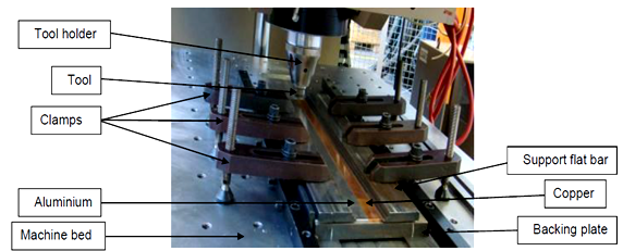 | Figure 2. Plates and the clamping system for the FSW[15] |
Friction Stir welds between 5754 Aluminium Alloy (AA) and C11000 Copper (Cu); 3.175 mm thick were produced at the Friction Processing Research Institute (FPRI) of Nelson Mandela Metropolitan University (NMMU), South Africa using an Intelligent Stir Welding for Industry and Research Process Development System (I-STIR PDS) platform. The welds were produced using three different shoulder diameter tools viz: 15, 18 and 25 mm with a constant tool pin diameter of 5 mm. The Copper sheet was placed at the advancing side while the tool pin was plunged in the Aluminium Alloy and made to touch Copper during the welding process; this is an optimised tool displacement setting according to Akinlabi et al.[14]. The schematic diagram of the plates and the clamping system is presented in Figure 2. The rotational speeds of 600, 950 and 1200 rpm were used to produce the welds, these represents a low, medium and high setting respectively, while 50, 150 and 300 mm/min were the feed rates considered also representing a low, medium and high setting respectively. An opticalmicroscope, Olympus PMG3 was used for the microstructural evaluation; the samples were cut at 50 mm from the weld start in a transverse direction. The modified Poulton’s reagent was used to reveal the microstructures of copper, which consists of 30 ml HCL, 40 ml HNO3, 2.5 ml HF, 12g CrO3, and 42.5 ml of H2O while the AA side was etched with Flicks reagent. The grain sizes of the joint interfaces were measured with the measurement tool on the microscope and the microhardness were measured along the cross sections of the welds with a load of 200 gf and a dwell time of 10 seconds, using an FM-ARS 9000 automatic indenter. The electrical resistances of the joints were measured using a Signatone Four-Point probe meter with 1.6 mm probe spacing and the sample cross sectional area was 127 mm2.
3. Results and Discussion
The results obtained in this research study are hereby presented and discussed in this section.
3.1. Microstructural Characterization
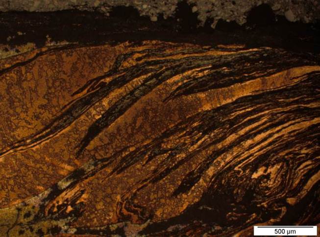
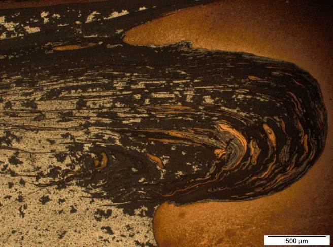
The microstructures of the joint interfacial regions of representative samples produced with the three shoulder diameter tools employed in this research work are presented in Figures 3 (a) to (c). The welds were produced at 600 rpm and 150 mm/min with the 15 mm, 18 and 25 mm shoulder diameter tools respectively.It was observed that the mixing of both materials was achieved leading to good metallurgical bonding at the joint interfacial regions. The black/silverish regions are etched aluminium rich while the golden yellow being copper rich regions. The joint interfaces are characterised by mixed layers of aluminium and copper as evident in the microstructures resulting from the heat input into the welds by the stirring of the tool during the FSW process. 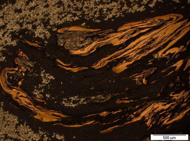 | Figure 3 (a). Microstructure of the weld produced at 600 rpm and 150 mm/min with the 15 mm shoulder diameter tool |
 | Figure 3 (b). Microstructure of the weld produced at 600 rpm and 150 mm/min with the 18 mm shoulder diameter tool |
 | Figure 3 (c). Microstructure of the weld produced at 600 rpm and 150 mm/min with the 25 mm shoulder diameter tool |
| Table 1. Grain size measurements in (µm) |
| | | Aluminium | Copper | | | SZ | TMAZ | HAZ | PM | SZ | TMAZ | HAZ | PM | | 1 | 3.38 | 5.67 | 52.64 | 58.18 | 4.07 | 12.36 | 22.6 | 55.91 | | 2 | 2.46 | 4.83 | 37.96 | 51.92 | 2.97 | 14.35 | 25.16 | 35.63 | | 3 | 3.17 | 3.46 | 43.66 | 57.25 | 5.76 | 15.19 | 18.82 | 38.39 | | 4 | 3.76 | 4.45 | 39.97 | 59.60 | 4.56 | 16.59 | 23.61 | 39.12 | | 5 | 3.29 | 4.38 | 45.49 | 49.93 | 1.67 | 20.53 | 21.17 | 49.63 | | Average | 3.21 | 4.56 | 43.94 | 55.34 | 3.08 | 15.80 | 22.27 | 43.74 | | %decrease | 94.2 | 91.8 | 20.6 | | 92.9 | 63.9 | 49.1 | |
|
|
3.2. Grain Size Measurements
The measurement tool on the microscope was used to measure five individual grains at the different zones in the microstructure of the weld produced at 600 rpm and 150 mm/min with the 15 mm shoulder diameter tool and the averages of the measurements were calculated. The results are presented in Table 1.It was observed that the percentage decrease in the grain sizes increases towards the stir zones of the welds. This is expected due to the predominant heat experienced at the stir zones as a result of the stirring of the tool at this region; hence the grains were recrystallised leading to a sharp decrease in the grain sizes.
3.3. Microhardness Profiling
The average Vickers microhardness values of the parent materials used in this research study – Aluminium Alloy (AA) and Copper (Cu) are HV 60 and HV 95, respectively. The Vickers microhardness profiles of the welds produced at 600 rpm and 150 mm/min with the 15, 18 and 25 mm shoulder diameter tools are presented in Figure 4.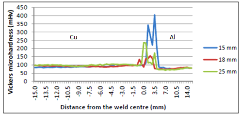 | Figure 4. Vickers microhardness of welds produced at 600 rpm and 150 mm/min with the 15, 18 and 25 mm shoulder diameter tools |
It was observed that there is an increase in the microhardness values at the joint interfaces of the welds resulting from strain hardening due to the stirring of the tool pin and the shoulder previously occupied by these regions during the welding process while the high peaks are due to the presence of intermetallics compounds resulting at the joints[16].
3.4. Electrical Resistivity Measurements
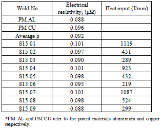
The results of the electrical resistivities of the welds measured, the process parameter settings at which they were produced and the heat input to the welds are presented in Tables 1 to 3 for the welds produced with the 15, 18 and 25 mm respectively. The heat input was calculated using equation (1):  | (1) |
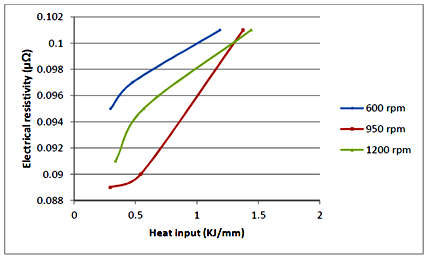
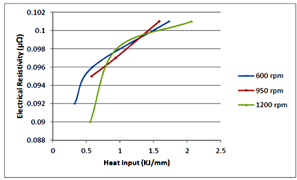
Where Q (J/mm) is the heat input, η is the efficiency factor (0.9 for Al and Cu), ω (rpm) the rotational speed, T (Nm) is the response torque and f (mm/min) the feed rate (traverse speed).The electrical resistivities of the welds ranged between 0.087 and 0.1 μΩ. It was observed that the welds with the highest electrical resistivity of 0.101 μΩ were measured in those welds produced with the high heat inputs. Table 1. Summary of joint electrical resistivity and heat input into the welds produced with the 15 mm shoulder diameter tool[13]
 |
| |
|
| Table 2. Summary of joint electrical resistivity and heat input into the welds produced with the 18 mm shoulder diameter tool[13] |
| | Weld No | Electrical resistivity, (μΩ) | Heat input (J/mm) | | S18 01 | 0.101 | 1185 | | S18 02 | 0.097 | 474 | | S18 03 | 0.095 | 296 | | S18 04 | 0.101 | 1374 | | S18 05 | 0.090 | 542 | | S18 06 | 0.089 | 293 | | S18 07 | 0.101 | 1439 | | S18 08 | 0.095 | 565 | | S18 09 | 0.087 | 337 |
|
|
| Table 3. Summary of joint electrical resistivity and heat input into the welds produced with the 25 mm shoulder diameter tool[9] |
| | Weld No | Electrical resistivity, (μΩ) | Heat input (J/mm) | | S25 01 | 0.101 | 1731 | | S25 02 | 0.096 | 590 | | S25 03 | 0.092 | 326 | | S25 04 | 0.101 | 1583 | | S25 05 | 0.097 | 934 | | S25 06 | 0.095 | 577 | | S25 07 | 0.101 | 2067 | | S25 08 | 0.098 | 950 | | S25 09 | 0.090 | 557 |
|
|
The plots of electrical resistivities versus the heat input into the joints at constant spindle speeds with respect to the shoulder diameter tools employed are presented in Figures 5 (a) to (c).From the Figures on electrical resistivity and the heat input into the welds presented in Figures 5 (a) to (c), it was observed that for all the weld settings, the joint electrical resistivities increases as the heat input increases at constant spindle speeds, although, there was no significant difference in the electrical resistivity measurements from one weld to the other.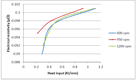 | Figure 5a. Electrical Resistivity versus Heat input of welds produced at constant rotational speed with the 15 mm shoulder diameter tool[13] |
 | Figure 5b. Electrical Resistivity versus Heat input of welds produced at constant rotational speed with the 18 mm shoulder diameter tool[13] |
 | Figure 5c. Electrical Resistivity versus Heat input of welds produced at constant rotational speed with the 25 mm shoulder diameter tool[13] |
4. Conclusions
Friction Stir joints of dissimilar aluminium and copper was successfully produced at various process parameter combinations. Microstructural evaluation of the joint interfaces showed good mixing of both materials due to adequate heat input into the welds during the welding process. 92% decrease was observed in the grain sizes at the stir zone compared to the parent materials. Higher Vickers microhardness values were also measured at the joint interfaces resulting from the heat input into the welds. The electrical resistivities of the joints produced within the parameter settings considered increased as the heat input to the welds increases. The maximum percentage increase in the resistivity compared to the average joint resistivity of the parent material was found to be 9.8%. Hence, the process parameter combinations employed in this research study can be recommended.
ACKNOWLEDGEMENTS
The authors wish to thank Dr. T. Hua and Mr L. Von Wielligh for operating the FSW platform, Mr G.C. Erasmus for assistance in the Metallurgy lab, Prof. A. Venter of Physics Department for assistance with the electrical resistance measurements and Prof A. Els-Botes for the opportunity to work in her research group; all of Nelson Mandela Metropolitan University, Port Elizabeth, South Africa. We will also like to thank the Tertiary Education Support Program (TESP) of ESKOM South Africa and the University of Johannesburg Research funding for financial support.
References
| [1] | Thomas W. M, Nicholas E. D., Needham J. C., Murch M. G., Templesmith P. and Dawes C. J. “Improvements relating to Friction Welding”. International Patent Application, PCT/GB92/02203 (Patent) December 1991. |
| [2] | Friction stir welding of aluminium. Online Available: http://www.alcotec.com Assessed May 2012. |
| [3] | Colligan K. J. and Mishra R. S., “A conceptual model for the process variables related to heat generation in friction stir welding of aluminium”. Scripta Materialia.. Vol. 58, pp. 327-331, 2008. |
| [4] | Blignault C, “A friction stir weld tool-force and response surface model characterizing tool performance and weld joint integrity”. D.Tech dissertation, Nelson Mandela Metropolitan University, Port Elizabeth, South Africa. 2007. |
| [5] | Reynolds A. P, “Friction stir welding of aluminium alloys”. In: Totten GE, MacKenzie DS (eds.) Handbook of Aluminium, Volume 2 Alloy Production and Materials Manufacturing. New York, Marcel Dekker; p. 579-700, 2003. |
| [6] | Nandan R., DebRoy T. and Bhadeshia H. K. D. H, “Recent advances in friction stir welding- Process, weldment structure and properties”. Progress in Material Science, vol. 53: pp. 980-1023. 2008. |
| [7] | Threadgill P. L, “Terminology in friction stir welding”. Science and Technology of Welding and Joining. 12(4): pp. 357- 360, 2007. |
| [8] | Saeid T, Abdollah-Zadeh A and Sazgari B. “Weldability and mechanical properties of dissimilar aluminium-copper lap joints made by friction stir welding” Journal of Alloys and Compounds 490: pp. 652-655, 2010. |
| [9] | Li, X, Zhang, D, Qiu, C and Zhang, W. “Microstructure and mechanical properties of dissimilar pure copper/1350 aluminium alloy butt joint by friction stir welding. Transactions of Nonferrous Metals Society of China 22: pp1298-1306, 2012. |
| [10] | Galvao I, Oliveira JC, Loureiro A and Rodrigues DM. “Formation and distribution of brittle structures in friction stir welding of aluminium and copper: Influence of shoulder geometry. Journal of Intermetallics. 22: pp. 122-128, 2012. |
| [11] | Bisadi H, Tavakoli A, Tour Sangsaraki, M and Tour Sangsaraki, K. “The influence of rotational and welding speeds on microstructures and mechanical properties of friction stir welded AL5083 and commercially pure copper sheets lap joints. Journal of Materials & Design, accepted manuscript. DOI:http://dx.doi.org/10.1016/j.matdes.2012.06.029. June 2012. |
| [12] | Savolainen K, Mononen J, Saukkonen T and Hänninen H. “A preliminary study on friction stir welding of dissimilar metal joints of copper and aluminium”. 6th International FSW symposium. Montreal, Canada. 10-13 October 2006. TWI (UK). Retrieved: CD-ROM, 2006. |
| [13] | Esther T. Akinlabi, Daniel Madyira and Stephen. A. Akinlabi, “Effect of heat input on the electrical resistivity of dissimilar friction stir welded joints of aluminium and copper”, in Proceedings of 2011 IEEE Africon International Conference in Livingstone, Zambia, between September 13-15th, 2011. |
| [14] | Esther T. Akinlabi, Annelize Els-Botes, Hannelie Lombard, “Effect of tool displacement on defect formation in Friction Stir Welding of Aluminium and Copper”, in Proceedings of 8th International FSW Symposium, Hamburg, Germany. 18-20 May 2010. |
| [15] | Esther T. Akinlabi, Material characterization of dissimilar joints between aluminium and copper. D.Tech Dissertation, Department of Mechanical Engineering, Faculty of Engineering, Built Environment and Information Technology, Nelson Mandela Metropolitan University, Port Elizabeth, South Africa. 2011. |
| [16] | Esther T. Akinlabi, “Effect of shoulder size on weld properties of dissimilar metal friction stir welds. Journal of Materials Engineering Performance. DOI:10.1007/s11665-011-0046-6. Online Available: October 2011. |
 Abstract
 Reference
 Full-Text PDF
 Full-Text HTML