P. Aditya Rama Kamalanath 1, Apu Sarkar 2
1Department of metallurgical and materials engineering, NIT Warangal, Warangal, 506004, India
2Mechanical metallurgy section, BARC, Mumbai, 400094, India
Correspondence to: P. Aditya Rama Kamalanath , Department of metallurgical and materials engineering, NIT Warangal, Warangal, 506004, India.
| Email: |  |
Copyright © 2012 Scientific & Academic Publishing. All Rights Reserved.
Abstract
Zircaloy-2 is mainly used in nuclear technology, as cladding of fuel rods in nuclear reactors, especially water reactors (BWRs). Hence high strength of Zircaloy-2 is of prime importance. This investigation deals with the effect of cryorolling on Zircaloy-2 by comparing different tensile properties. For this analysis, four samples with various degrees of cryorolling are taken and tensile tests are conducted on these samples. The obtained results are analyzed and the optimum degree of cryorolling of Zircaloy-2 is obtained. The cryorolling improved the mechanical properties of the material as the dislocations are entangled near the grain boundaries and also due to decrease in the grain size. The microstructure of the sample is analysed by optical microscope, before and after cryorolling and the grain structure analysis is done.
Keywords:
Zircaloy-2, Cryorolling, Entanglement of Dislocations, Dynamic Recovery, Degree of Cryorolling
Cite this paper:
P. Aditya Rama Kamalanath , Apu Sarkar , "Tensile Behavior of Cryorolled Zircaloy-2", American Journal of Materials Science, Vol. 2 No. 5, 2012, pp. 138-141. doi: 10.5923/j.materials.20120205.01.
1. Introduction
Zirconium has very low absorption cross-section of thermal neutrons, high hardness, and ductility and corrosion resistance. Hence its alloys are mainly used in nuclear reactors for the cladding of fuel rods. Zircloy-2 is one such alloy which is mainly used in boiling water reactors (BWR)[1]. In the recent past, water reactors of higher capacity are being developed .In the late 1990s GE Hitachi (GEH) and Toshiba has produced advanced boiling water reactor (ABWR). The standard ABWR plant design has a net output of about 1350 MWe (3926 MWth). Various tests are being conducted on zircaloy-2 at such high burn-up[2], and while the zircaloy-2 cladding has had a very good track record of safe use in nuclear reactors, the material becomes susceptible to failure over long times disowning to its strength aspects for the above ABWRs at such high burn-up[4].As a result, fuel rods are often taken out of service even though they may have a substantial amount of fuel remaining to produce energy [3]. So methods which increase the strength of zircaloy-2 without decreasing its ductility and corrosion resistance are being explored.Cryorolling, deformation at cryogenic temperature is proved to be effective method for increasing the yield strength and tensile strength for various Al alloys [5][6]. So this technique is implemented on zircaloy-2. Also optimum degree of cryorolling for zircaloy-2 is also found in this investigation.
2. Experimental Procedure
Process of cryorolling: The samples are dipped in LN2(liquid nitrogen) for 10min before first pass and 2 min for each pass, sample was found to attain nearly -1600C. The process is controlled by microprocessors in order to avoid thermal shocks and also damage to the components. Here in cryorolling as the material cools its molecular structure contracts and hence there is entanglement of dislocations near the grain boundaries [7]. The samples are cryorolled up to three degrees of rolling (leaving the annealed sample) .One up to 20%; another to 50%: and the last one up to 70% of cryorolling. The standard tensile rectangular flat specimens are prepared according to ASTM E8 for the four samples [8]. Then the material is tested on Instron model 1185 Screw driven Universal Testing Machine and the testing data is supervised by blue-hill software to get the required data of the material.| Table 1. The specifications of the samples used for the tensile testing |
| | Sample | Thickness(mm) | Width(mm) | Cross-sectional area(mm2) | Gauge length(mm) | | Annealed | 4.02 | 4.36 | 17.53 | 10 | | 20% cryorolled | 3.69 | 4.12 | 15.20 | 10 | | 50% cryorolled | 1.99 | 4.11 | 8.19 | 10 | | 70% cryorolled | 1.31 | 4.08 | 5.34 | 10 |
|
|
Initially when the sample is loaded on the upper grip there won’t be any load on the sample but that recorded on the blue hill window is that of the load due to the grip. It is therefore set to zero in order to balance that load. The sample is then fixed to the lower grip. The test is then started with a strain rate of 10-3 s-1. The crosshead speed i.e. the speed by which the crosshead moves is determined from the strain rate. Strain rate = crosshead speed/gauge length which gives the crosshead speed as 0.01 mm/s.The test is started and the load- elongation data along with its graph are obtained which are further processed in order to evaluate the mechanical properties [9][10].Then graphs are simulated using the data obtained for both annealed sample and cryorolled sample using ORIGIN PRO software.
3. Results and Discussion
On comparing the Engineering stress-strain curves for the four samples [11].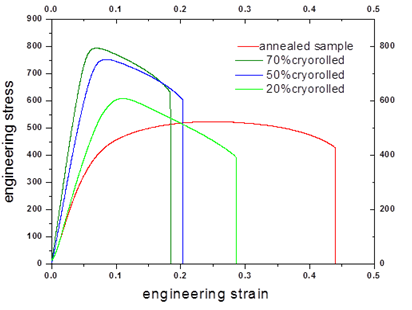 | Figure 1. The engineering stress-strain curves of the four samples compared |
This shows that the Yield stress and the Ultimate tensile stress of the sample increase with the % of cryorolling.
3.1. The Values Obtained from the Graph:
| Table 2. The Yield stress, Ultimate Tensile stress and the elongation of the four cryorolled samples |
| | | Annealed sample | 20% cryorolled sample | 50% cryorolled sample | 70% cryorolled sample | | Yield stress | 381MPa | 496.5 Mpa | 668.9 Mpa | 732.3 Mpa | | Ultimate Tensile stress | 523.26 Mpa | 609.5 Mpa | 753.5 Mpa | 795.9 Mpa | | eu | 0.23 | 0.106 | 0.083 | 0.07 |
|
|
The true stress-strain curves have been drawn from the Engineering stress-strain curves up to the onset of necking.When the specimen is loaded in the testing machine the load is transmitted to the specimen as well as to the machine. So this makes the machine to deform elastically. Therefore in the true stress –strain cure it includes even the elasticity of the machine which is to be corrected. The slope of the elastic region gives the combined modulus of elasticity. This divided by the instantaneous stress gives the strain in elastic region which is subtracted from the true strain to get the corrected true strain and similarly corrected true stress was found out and the graphs were deduced.
3.2. Strain Hardening Curve
The strain hardening exponent (n) depicts the relative amount a metal strain hardens before undergoing fracture. It was found by fitting a curve of the form y=a + bxc as σ=σ0+Kεn to the corrected True stress and strain curve and getting the value of c[12].The curve fitted plots are indicated by the red colour line obtained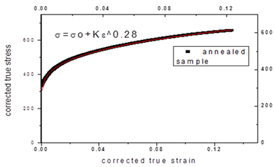 | Figure 2. The flow curve fitted to the corrected true stress-strain curve of annealed sample |
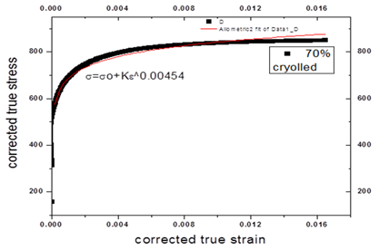 | Figure 3. The flow curve fitted to the corrected true stress-strain curve of 70% cryorolled sample |
It is found that the value of n is found to decrease from the annealed sample to 70% cryorolled sample indicating that the mean free path of the dislocations has decreased with cryorolling due to their increasing density by the previously produced dislocations and newly produced one [13].| Table 3. The values of strain hardening exponent of the four samples |
| | | AnnealedSample | 20%cryorolled | 50%cryorolled | 70%cryorolled | | n | 0.28 | 0.04 | 0.019 | 0.004 |
|
|
3.3. Work Hardening
These curves are drawn between θ (dσ/dε) and the corresponding corrected true stress (σ) and true strain (ε) and the Work hardening behaviour of the specimen is indicated with the help of these curves. More the steepness of the curve, more being the recovery of the dislocations. They are obtained as: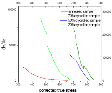 | Figure 4. The work hardening curves of the four samples compared |
These curves show that there is a decrease in the dynamic recovery pace with the % of cryorolling [14].
3.4. Microstructure Analysis
The microstructures of annealed sample and that of the 70%cryorolled are observed under the microscope after undergoing a set of metallographic polishing operations. Both the samples are cut and mounted using a Bakelite resin and the moulds were polished on Sic papers of grade from 800 to 2400 papers on STRUERS polisher. Final polishing is done with help of 3 µm and1 µm diamond particles suspended in solution. The samples are then etched in a chemical solution containing 45ml HNO3+45ml H2O+.10ml HF as the etchant [15].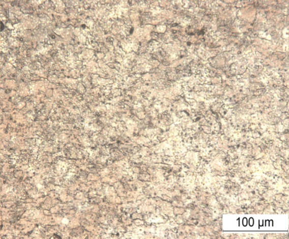 | Figure 5. Optical microscope Image of Annealed sample |
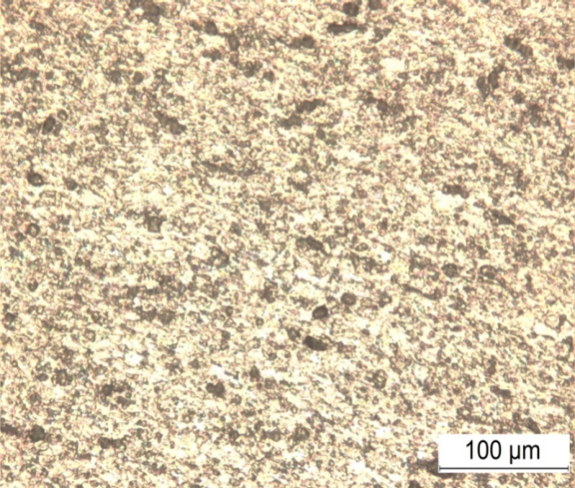 | Figure 6. Optical microscope Image of 70% cryorolled sample |
There is a noteworthy decrease in the grain size from annealed sample to 70% cryorolled sample i.e. with the increased amount of rolling [16].
4. Conclusions
We observe that with the increasing amount of cryorolling there is a significant increase in the Y.S and U.T.S at the cost of its ductility. An optimum degree of cryorolling is obtained between 20%-50% of cryorolling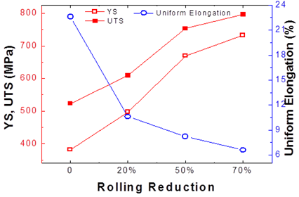 | Figure 7. The Y.S, U.T.S, % elongation of the four samples compared |
Due to cryorolling, we geta) Fine grain size andb) More dislocation densityc) Suppression of dynamic recovery.a) Fine grain size: Normally for annealed sample the dislocations are present within the grain and the grain boundaries. When some stress is applied, the dislocations move along one grain to another. In this process, when it comes through another grain, it encounters a barrier due to the misorientation of the crystallographic texture from one grain to another. Thus some additional force is required to move the dislocations across the barrier. Now due to cryorolling, since the grain size is reduced, there is an increase in the number of grains and overall grain boundary and therefore the size of the overall barriers for the dislocations increases and more force is required for the dislocations to cross the barrier which in turn increases the strength of the material.[16][17]b) More dislocation density: Due to rolling, quite a large number of dislocations are produced. These dislocations get entangled between the grain boundary which impedes their motion and the strength gets increased.With the increasing extent of cryorolling, more amount of dislocations get piled up within the grain boundaries and the sample starts to fracture after quite some time with increasing stress. Thus the ductility gets decreased with the extent of cryorolling at the cost of its strength.c) Suppression of dynamic recovery: There is suppression of dynamic recovery as in cryogenic temperature, the total internal energy of the atoms decreases as it is a function of temperature of the material. So the atoms kinetic energy decreases which results in the suppression of dynamic recovery [18].Thus cryorolling has been found effective in increasing the mechanical properties of the Zircaloy-2 sample if the optimum amount of rolling is been chosen to have both enough strength and ductility. It is found that the rolling ductility decreases steeply from 10-20% of rolling and after which much decrease has not been observed. Thus depending on the ductility and strength preferred the degree of rolling is to be chosen. Due to the very fine grain size obtained there has been only a petite decrease in ductility with the increase in strength. However these cryorolled samples lack sufficient corrosion resistance far from expected and can be improved on further research [19].
References
| [1] | K. L. Murty: Zirconium in the Nuclear Industry ASTM STP 1023 (1989) 570–595. |
| [2] | Weblink:http://www.ne.anl.gov/capabilities/ip/highlights/light_water_reactor.html |
| [3] | Weblink:http://www.energyblogs.com/coretech/index.cfm/2011/1/31/Interest-Builds-for-New-Nuclear-Fuel-Cladding |
| [4] | K. Kallstrom, T. Andersson and A. Hofvenstam: Zirconium in the Nuclear Industry, ASTM STP 551 (1974) 160–168 |
| [5] | K. Gopala Krishna, Nidhi Singh, K. Venkateswarlu and K. C. Hari Kumar, Tensile Behavior of Ultrafine-Grained Al-4Zn-2Mg Alloy Produced by Cryorolling, Journal of Materials Engineering andPerformance,DOI:10.1007/s11665-011-9843-1,1 february. 2011, springerlink. |
| [6] | SUSHANTA KUMAR PANIGRAHI,R.JAYAGANTHAN, Effect of Annealing on Thermal Stability, Precipitate Evolution, and Mechanical Properties of Cryorolled Al 7075 Alloy, DOI: 10.1007/s11661-011-0723-y,The Minerals, Metals & Materials Society and ASM International 2011. |
| [7] | Gopala Krishna, K., Singh, N., Venkateswarlu, K., & Hari Kumar, K. C. (2011). Tensile Behavior of Ultrafine-Grained Al-4Zn-2Mg Alloy Produced by Cryorolling. Journal of Materials Engineering and Performance, 20, 1569-157. |
| [8] | R. Gedney, Guide To Testing Metals Under Tension, Advanced Materials & Processes, February, 2002, p 29–31. |
| [9] | ASM Metals Reference Book, third ed. ASM International, Materials Park (OH) 2004, p. 414. |
| [10] | Hayden.H.W,W.G.Moffat and J.Wulff The structure and properties of materials; Vol III Mechanical behaviour,Wiley,NewYork. |
| [11] | STRESS-STRAIN CURVES David Roylance Department of Materials Science and Engineering Massachusetts Institute of Technology Cambridge, MA 02139. |
| [12] | Physics and phenomenology of strain hardening: the FCC case ;U.F. Kocks a, H. Meckingb, *aLos Alamos National Laboratory bMaterial Science and Technology, TU Hamburg Harburg, Eissendorfer Str. 42, 21071 Hamburg, Germany. |
| [13] | Dislocation mean free paths and strain hardening of crystals.Devincre B, Hoc T, Kubin L.Laboratoire d'Etude des Microstructures, Unité Mixte de Recherche (UMR) 104 CNRS, CNRS-Office National d'Etudes et de Recherches Aérospatiales (ONERA), 20 Avenue de la Division Leclerc, BP 72, 92322 Chatillon Cedex, France. |
| [14] | On the mechanisms of dynamic recovery E Nesa, K Marthinsena, , , Y Brechetb a Department of Materials Technology and Electrochemistry, Norwegian University of Science and Technology, N-7491 Trondheim, Norway b LTPCM-INPG, Domaine Universitaire de Grenoble, 38402 Saint Martin d'Heres Cedex, France. |
| [15] | Metallography and Microstructures of Zirconium, Hafnium, and Their Alloys Author(s): Paul E. Danielson, U.S. Department of Energy; Richard C. Sutherlin, Wah Chang. |
| [16] | The microstructure evolution and mechanical properties of cryorolled Al alloys : Sabirov, Ilchat, Timokhina, Ilana, Barnett, Matthew and Hodgson, Peter 2008, The microstructure evolution and mechanical properties of cryorolled Al alloys, in Metal Forming 2008 : Proceedings of the 12th International Conference on Metal Forming, Verlag Stahleisen GmbH, Duesseldorf, Germany, pp. 190-194. |
| [17] | Development of ultrafine grained high strength Al–Cu alloy by cryorolling T. Shanmugasundaram, B.S. Murty, V. Subramanya Sarma *Department of Metallurgical and Materials Engineering, Indian Institute of Technology Madras, Chennai, Tamil Nadu 600 036, India. |
| [18] | RD Doherty; DA Hughes; FJ Humphreys; JJ Jonas; D Juul Jenson; ME Kassner; WE King; TR McNelley; HJ McQueen; AD Rollett (1997). "Current Issues In Recrystallisation: A Review". Materials Science and Engineering A238: 219–274. |
| [19] | Gopala Krishna, K., Sivaprasad, K., Sankara Narayanan, T. S. N., & Hari Kumar, K. C. (2012). Localized corrosion of an ultrafine grained Al-4Zn-2Mg alloy produced by cryorolling. Corrossion Science, 60, 82-89. |
 Abstract
 Reference
 Full-Text PDF
 Full-Text HTML