Zenasni Ramdane1, Hebbar Ahmed1, Jaime Vina Olay2
1Department of Mechanics, University of Mostaganem, Laboratory LMNEPM, Mostaganem, BP882 RP, 27000, Algeria
2Department of Material Sciences, University of Oviedo, Gijon, 33204, Spain
Correspondence to: Zenasni Ramdane, Department of Mechanics, University of Mostaganem, Laboratory LMNEPM, Mostaganem, BP882 RP, 27000, Algeria.
| Email: |  |
Copyright © 2012 Scientific & Academic Publishing. All Rights Reserved.
Abstract
The present study was carried out to evaluate the temperature effect on the mode II interlaminar fracture behaviour of two unidirectional carbon fiber composite materials subject to low velocity impact damage. Before testing, the specimens were exposed at positive and negative temperatures. The delamination crack energy was calculated at the maximum loading point according to the directed beam theory, to the corrected beam theory and to the compliance calibration. Two types of carbon fiber epoxy composite materials were investigated of denominations AS4/8552 and AS4/3501-6. Unidirectional panels of 32 plies were fabricated according to the prepreg manufacturer`s. A thin film of PTFE was introduced between the mid-planes of the panels in order to provide an artificial starter crack of length 60 mm. Of each materials, five specimens were tested at the statically and the dynamical mode II at the temperatures of:-30,-15, 0, 15, 30, 45 and 60°C. From the experimental results, we conclude that the two composites have a similar behaviour, with a slightly effect of a temperature. The experimental design method was used to obtain a mathematical model describing the effect of the temperature on the crack delamination energy. The compliance calibration method gives conservative values of the crack delamination energy.
Keywords:
Unidirectional Carbon Fiber, Matrix Epoxy, Delamination, Mode II, Positive Temperature, Negative Temperature, Low Velocity Impact Damage, Experiment Design Method
1. Introduction
Composite materials have been a staple of the engineering community for many decades. In many engineering applications of composites and laminate materials, damage and failure may be caused by impact of various natures. Low-velocity impact is potentially dangerous because it can produce extensive subsurface delamination that may not be visible on the surface. The composite materials were used in the aerospace and the aircraft vehicles. Moisture can adversely affect composites integrity, durability and performance. In the recent years characterization and mechanical behaviour of polymer composites at a temperature has been focused. These are the modern engineering materials that have wide applications in a range of areas from aerospace, automobiles and boats to cryogenic equipments such as cryogenic fuel thanks, cryogenic fuel delivery lines, cryogenic wind tunnels and parts of the cryogenic side of turbo-pumps because of their ease of handling, low fabrication cost and excellent mechanical properties. As composites have demonstrated to be very venerable to out of plane impact, which cause barely visible impact damage (BVID) reportedly contributes up to 60% loss in structures’ compressive strength and major reason of catastrophic failures. The energy absorbed during impact is mainly dissipated by a combination of matrix damage, fibre fracture and fibre-matrix de-bonding, which leads to significant reductions in the load carrying capabilities. In ballistic impacts the damage is localized and clearly visible by external inspection, while low velocity impact involves long contact time between impactor and target, which produces global structure deformation with undetected internal damage at points far from the contact region. For such reasons the low velocity impact are often simulated by simple static indentation-flexure tests, neglecting the influence of dynamic effects. It is also suggested the complete model to take into account the full dynamic behaviour of the laminates. When the temperature is decreased down to cryogenic temperature internal stresses are generated in the epoxy matrix due to thermal contraction. Fracture of the matrix is induced when the thermal stress induced stress intensity factor exceeds the fracture toughness of the resin. The fracture toughness of the matrix at cryogenic temperature can be improved by controlling the chemical structure, network structure and morphology. The microstructure becomes more orderly at low temperature [1]. Other researchers applied damage theory of continuum mechanics to address the internal damage. They initiated the stress-strain relation for the actual damaged by introducing a fourth-order damage operator to transform the compliance matrix according to the damage states. The impact induced de-lamination another important damage mode was combined because the level of impact energy to initiate de-lamination is low and the post-impact compressive strength reduces dramatically. R.Tiberkak and al [2] have analysed the damage of composite plates under a low velocity impact loading. Since 1980s, many researchers have analytically and experimentally investigated the low velocity impact behaviour of composite laminated structures. Most composite structures will be under some level of stress when impacted. For example, the upper skin of the main wing of the aircraft will be mainly under in-plane compressive load during flight and the lower one will be under in-plane tensile load. So, foreign objects like hail and debris in the runway shall give an impact to 638. Umar Farooq and Karl Gregory [3] have studied a composite laminated structure under in-plane load. However, a few studies on the impact behaviour of the composite laminates under in-plane load have been published. Ramazan Karakuzu and al [4] have used the LS Dyna a finite element program to analyse the impact delamination response of the composite laminate subjected to a different impactor mass. C. Cho and al [5] have studied the effect of the geometry and a material on the mechanical response laminated composites subjected to a low velocity impact damage. A finite element analysis of fibre-reinforced composite plates subjected to low velocity impact has been also done by M. Freitas and al [6]. Gaurav Nilakantan and al [7], have used the multi-scale modelling techniques to analyse the impact damage of woven fabric by the finite element. In the present paper, two symmetrical unidirectional carbon fiber composite materials were subjected to the impact loading before they have been exposed to positive and cryogenic temperatures in order to characterise the interlaminar mode II fracture behaviour to impact damage response.
2. Experimental Procedures
2.1. Materials
Two types of carbon fiber /epoxy composite materials were investigated in the present study. One of commercial denomination AS4/8552 is a modified epoxy matrix 8552 in order to increase their tenacity. The second of denomination AS4/3501-6 is a conventional composite of matrix epoxy 3501-6. Unidirectional symmetrical panels of 32 plies were fabricated according to the prepreg manufacturers recommended cure cycle. A thin film of PTFE was inserted between the mid planes of the panels to provide an artificial crack starter. The specimen dimensions were of 6 mm thickness, 25 width and 160 mm long. The starter length was of 60mm, five specimens of each material were exposed to positive and cryogenic temperatures. The chosen temperatures were: -30°,-15°, 0°, 15°, 30°, 45° and 60°.
2.2. Impact loading
After the temperature conditioning, the compliance calibration had been realized. All the specimens were tested to impact loading according to ASTM [8] in order to determinate the maximum load and the energy required to impact delamination. The impact tests were conducted in a drop tower at a velocity of 4.43 m/s during a short time test of 50ms. The figure 1, present the ENF impact test. The crack energy GIIC was calculated at the maximum load point.Experimental calibration method (1):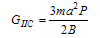 | (1) |
Direct beam theory (2):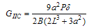 | (2) |
Corrected beam theory (3):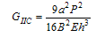 | (3) |
Where:B is the specimen width, h the half thickness, P the load, δ the displacement at the maximum load, a was the crack length, L is the middle span. The slope m where calculated from:  E is the Young modulus calculated using the equation 4:
 | (4) |
was the origin ordinate calculated for 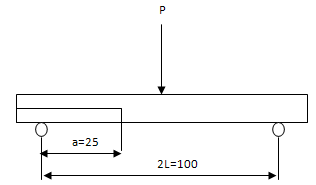 | Figure 1. ENF test |
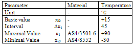
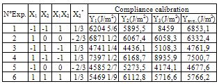
By applying the design experiment method, the coded values were presented in table1. In tables 2, 3 and 4, we present the type of experiment. Where: X1: material type (AS4/8552 and AS4/3501-6), X2: Temperature, Y delamination energy (J/m2).Table 1. The influencing parameters
 |
| |
|
Where the coefficient of regression where:Compliance calibration method:β0 = 5513.36; β1 = 67.77; β2 = -956.42; β12 = 89.18;β22 = 710.07Direct beam theory:β0 = 16056.47; β1 = -772.67; β2 = 969.68; β12 = 417.87;β22 = 3023.07Corrected beam theory:β0 = 8111.82; β1 = -260.05; β2 = 105.71; β12 = 94.67; β22 = 597.35
2.3. Experimentation
In order to optimize the mechanical testing, the planning design experiment method was used to obtain a mathematical model describing all the influencing parameters. The experimentation is made on a bench test, show figure 2, according to a planning of experiments of second order and of type two requiring 6 experiments under the influence of parameters whose values are reported in table1. In fact of the diversity of the units, according to [9-12] the values were coded by the relation (5): | (5) |
Where:Xi: coded valuexi: real superior (inferior) valuexio: real intermediary value∆xi: IntervalBy applying the compliance calibration method, a mathematical model can be obtained in the form: 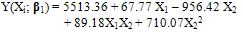 | (6) |
There surface responses can be represented in figure 2a.Similarly, the direct beam theory provided a mathematical model in the form: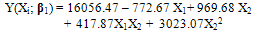 | (7) |
Figure 2b, show the surface responses on this model. At the end, the corrected beam theory provided a mathematical model listed below: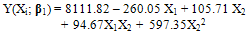 | (8) |
There surface responses can be also presented in figure 2c.From figure 2a, in the case of compliance calibration, we note that the delamination energy decrease linearly and fastly for two composite materials (AS4/8552 and AS4/3501-6) for temperature variation of -30℃ to -11.1℃. From -11.1℃ to 27.6℃, the delamination energy decrease linearly and slowly reaching the value of 5400 J/m2, where the temperature had more effect on the composite AS4/3501-6. From the temperature variation of 27.6℃ to 42℃, the delamination energy decrease no linearly and slowly reaching the value of 5200 J/m2 and then begin in increase no linearly and slowly to reach the value of 5400 J/m2 (Figure 2a).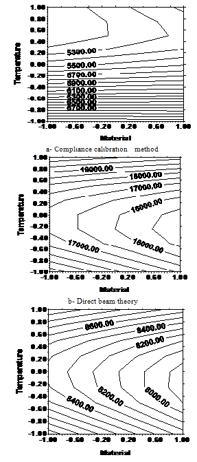 | Figure 2. (a, b, c)Effect of the material type and the temperature on the energy of delamination |
For a temperature range from -30℃ to 6℃, the delamination energy for a composite AS4/3501-6 decrease linearly to 11.1℃ then no linearly and slowly. In the case of composite AS4/8552, the energy decrease no linearly and slowly at the same range of temperature. From temperature variation of 6℃ to 42℃, the energy increase no linearly and slowly, finally from 42℃ to 90℃, the energy of delamination increase linearly. We that the cryogenic temperatures have more influence on the composites AS4/8552 and AS4/3501-6 from -30℃ to 6℃ and a contrary for the temperatures variation between 6℃ to 90℃, see figure 2b (direct beam theory).For a temperature range of -30℃ and 15℃, the delamination energy decrease linearly, and then no linearly, this variation had a great effect on the composite AS4/8552. By varying the temperature from 15℃ to 90℃, the energy will have a linearly and no linearly growth for a composite AS4/3501-6, see figure 2c (corrected beam theory). From the obtained results, we appreciate that the direct beam theory provided a higher delamination energy values. The corrected beam theory gives averaged values of delamination crack energy. Finally the compliance calibration gives conservative values of delamination energy. Table 2. Compliance calibration method
 |
| |
|
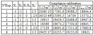
Table 3. Direct beam theory
 |
| |
|
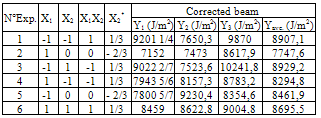
Table 4. Corrected beam theory
 |
| |
|
Figure 3, present the variation of impact energy en function of the temperature. In the case of the material AS4/3501-6, we note a stabilization of the energy between 0 ℃ and 15℃, followed by a quickly decrease in energy for a change of the temperature between 15℃ to 60℃ reaching the value of 22.15J. At a cryogenic temperatures -30℃ to -15℃ reaching the value of 29.93J, then the impact energy was maintained followed by a slowly decrease at 0℃. The composite AS4/8552, present more or less the same trend as the material AS4/3501-6 with a modified matrix. At temperature of 60℃, the composite AS4/8552 presents a decrease in impact energy about 26.9J. In mode II, the modified epoxy matrix had no significantly effect on the impact energy.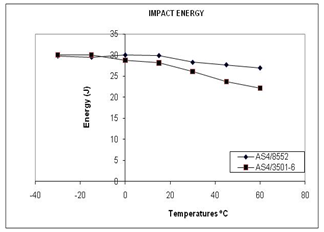 | Figure 3. Energy impact en function of temperature |
3. Conclusions
Two composite materials were subjected to impact damage loading at a low velocity in a drop tower. The composites were made of unidirectional carbon fibers of 32 plies. The first composite had a matrix epoxy without any modification, while the second composite of a modified epoxy matrix in order to increase their fracture tenacity. Before the impact testing, the composites were subjected to temperatures of: 60℃, 45℃, 30℃, 15℃, 0℃, -15℃ and -30℃. The impact delamination energies were calculated at a maximum load point according to three theories (compliance calibration, direct beam, and corrected beam). The planning design experiment method was applied in order to obtain a mathematical model taking account all the influencing parameters on the impact delamination energy. From the results, the compliance calibration theory gives more conservative values of the crack delamination energy. The temperatures generate thermal stresses in the laminate at low temperature; contribute to facility of the generation and propagation of damage when subjected to impact load.
ACKNOWLEDGMENTS
I would like to thank all the Staff of the material Sciences Department of the University of Oviedo at Spain for the helps provided during the mechanical testing.
References
| [1] | Takayuki Kusaka, Experimental characterization of interlaminar fracture behaviour in polymer matrix composites under low velocity impact loading, JSME, Vol.46, Nº.3, 328-334, 2003. |
| [2] | R. Tiberkak, M. Bachene, S. Rechak and B. Necib, Damage prediction in composite plates subjected to low velocity impact, Compos Struct 83 (2008), pp. 73–82. |
| [3] | Umar Farrok, Finite Element Simulation of Low Velocity Impact Damage Morphology in Quasi_Isotropic Composite Panels Under Variable Shape Impactors, European Journal of Scientific Research ISSN 1450-216X Vol.25 No.4 (2009), pp.636-648, Euro-Journals Publishing, Inc. 2009. |
| [4] | Ramazan Karakuzu, Emre Erbil, Mehmet Aktas, Damage prediction in glass/epoxy laminates subjected to impact loading, Indian Journal of Engineering &Materials Sciences, Vol.17, June 2010, pp.186-198 |
| [5] | C. Cho and G. Zhao, Effects of geometric and material factors on mechanical response of laminated composites due to low velocity impact, J Compos Mater 36 (2002), pp. 1403–1428. |
| [6] | M. de Freitas, A. Silva and L. Reis, Numerical evaluation of failure mechanisms on composite specimens subjected to impact loading. Composites: Part B 31 (2000), pp. 199–207. |
| [7] | Gaurav Nilakantan and al. On the finite element analysis of woven fabric impact using multiscale modeling techniques, International Journal of solid and Structures 47 (2010) 2300-2315. |
| [8] | Davies P., Blackman B.R.K., Brunner A.J., Mode II delamination. Fracture Mechanics Testing Methods for Polymer Adhesives and Composites. Ed. Moore D.R., Pavan A. y Williams J.G.,ESIS publication 28, Elsevier; (2001). |
| [9] | E. Scheffler, Einfürung in die statistischen Versuchsplannung, VEB Deutscher Verlag für Grundstoffindustrie, Leipzig (1986)72. |
| [10] | K. M. Fedosov, Planification des expériences, Ed. Soudostroegné, Leningrad (1978)68. |
| [11] | V. V. Nalimov, N. A. Tschernova, Méthodes statistiques de planification extrémale des expériences, Ed. Naouka, Moscou (1965)12. |
| [12] | V. Kafarov, Méthodes cybernétiques et technologie chimique, Ed. MIR, Moscou (1974) 205. |
 Abstract
 Reference
 Full-Text PDF
 Full-Text HTML