-
Paper Information
- Next Paper
- Previous Paper
- Paper Submission
-
Journal Information
- About This Journal
- Editorial Board
- Current Issue
- Archive
- Author Guidelines
- Contact Us
American Journal of Materials Science
p-ISSN: 2162-9382 e-ISSN: 2162-8424
2012; 2(2): 22-27
doi: 10.5923/j.materials.20120202.05
Solid Particle Erosion of Short Glass Fiber Reinforced Polyester Composite
 Abstract
 Reference
 Full-Text PDF
 Full-Text HTML
Ritesh Kaundal 1, Amar Patnaik 1, Alok Satapathy 2
1Department of Mechanical Engineering, N.I.T.Hamirpur, 177005 (H.P), India
2Department of Mechanical Engineering, N.I.T.Rourkela, 769008 (Orissa), India
Correspondence to: Amar Patnaik , Department of Mechanical Engineering, N.I.T.Hamirpur, 177005 (H.P), India.
| Email: |  |
Copyright © 2012 Scientific & Academic Publishing. All Rights Reserved.
This paper investigates the physical, impact behaviour and erosive wear properties of polyester composite materials reinforced with five different glass fibre loading (10, 20, 30, 40 and 50 wt.-%). Erosive wear property is studied under different impingement angles (30° to 90°), different impact velocities (43 m/s to 65 m/s) and dry silica sand particle (350 µm) is used as an erodent material. The results indicates that in case of erosive wear composite with 30 wt.-% of glass fiber contents shows better erosion resistance both in impingement angle and impact velocity effect as compare to the other composites. The physical properties and impact strength of the investigated composites found to be improving with fiber loading. At last the morphologies of eroded surface are examined by the scanning electron microscopy to investigate the nature of wear and material damage mode.
Keywords: Polymer Composite, Short Glass Fiber, Polyester, Erosive Wear
Article Outline
1. Introduction
- Fiber-reinforced high performance engineering polymers are widely applied in various fields of engineering[1,2]. The use, in primary structures, of fibre reinforced polymer has increased in the last decades due to their unique properties. Advantages are related with their low weight, high strength and stiffness. Although the development of these materials have been mostly related with aerospace and aeronautical applications, recent years have seen the spread of their use in many other industries, like automotive, where high production rates are required. Also Polymers and composites especially fiber-reinforced composites (FRCs) form a very important class of tribo-materials and are used where components are supposed to run without any external lubricants. Performance of such components, however, is generally sensitive to application conditions. It is also a well-accepted fact that no material is universally resistant to all modes of wear. Hence, during material selection for typical tribo- applications it becomes imperative to know its complete spectrum of behavior in various possible wearing situations. Interestingly, less is reported on systematic studies on wear behavior of materials in diverse wearing situations and operating conditions. Erosion is in analogy with repeated impact. In the case of erosion, the impact process is caused by many fast moving small particles whereas low-energy repeated impact (also called impact fatigue) is usually generated by a large mass of low velocity[3]. Localized damage induced by solid particle impact can significantly reduces the strength of the structures, jeopardizing their function and integrity. For fiber-reinforced polymers (FRP), matrix characteristics (e.g. cross link density), fiber characteristics (content, arrangement and property) and the interfacial bond strength between the fibers and the matrix highly influence the composite erosion rate[4]. Generally, the composite with short glass fiber is more erosion resistance as compare to the unidirectional, long fiber reinforced fiber composite reinforcement fibers[5,6]. Due to the occurrence of erosion process in fiber reinforced composite, the different sequence of damages in composite takes place i.e. local removal of material in the resin rich zones, erosion in the fiber zones associated with breakage of fibers in which the fibers act as brittle material and erosion of the interface zones between the fibers and the matrix[2,7]. Compared to continuous fiber composites, short fiber reinforced polymers (SFRP) combine easier process ability with low manufacturing cost. Therefore, in recent years the use of SFRP composites grows rapidly in many engineering applications, in particular in automobile and mechanical engineering industry[8]. So, it is very valuable to study the erosion resistance of advanced composites, to find methods to improve their resistance, to describe their property degradation and damage growth characteristics and finally to model their residual properties.In view of this, the aim of present investigation is to study the effect of short glass fiber reinforcement on the erosive wear behavior under multiple impact conditions in polyester resin and also on physical properties and impact strength of the composite.
2. Experimental Details
2.1. Composite Fabrication
- Short glass fibres (elastic modulus of 72.5 GPa and possess a density of 2.59 gm/cc) (Twaron, Teijin) of 6 mm length are used to prepare the composites. The Unsaturated isophthalic polyester resin (Elastic modulus 3.25 GPa, density 1.35 gm/cc) is manufactured by Ciba Geigy and locally supplied by Northern Polymers Ltd. . The composites are made by conventional hand lay-up technique. Two percent cobalt nephthalate (as accelerator) is mixed thoroughly in isophthalic polyester resin and then 2% methyl-ethyl-ketone-peroxide (MEKP) as hardener is mixed in the resin prior to reinforcement. Composites of five different fibers loading 10 wt.-% to 50 wt.-% are made. The castings are put under load for about 24 h for proper curing at room temperature. Specimens of suitable dimension are cut using a diamond cutter for physical, mechanical characterization and erosion testing.
2.2. Test Apparatus
- Figure 1 shows the schematic diagram of erosion test rig confirming to ASTM G 76.The set up was capable of creating reproducible erosive situations for assessing erosion wear resistance of the prepared composite samples. The erosion tester consists of an air compressor, an air particle mixing chamber and accelerating chamber. Dry compressed air was mixed with the particles which are fed at constant rate from a sand flow control knob through a convergent brass nozzle of 4 mm internal diameter. These particles impact the specimen which can be held at different angles with respect to the direction of erodent flow using a swivel and an adjustable sample clip. The velocity of the eroding particles was determined using double disc method[9]. In the present study, dry silica sand (spherical) of different particle sizes (350 µm) were used as erodent. The samples were cleaned in acetone, dried and weighed to an accuracy of ± 0.1 mg accuracy using a precision electronic balance. It is then eroded in the test rig for 10 minutes and weighed again to determine the weight loss. The process was repeated till the erosion rate attains a constant value called steady state erosion rate.
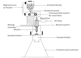 | Figure 1. Schematic diagram of an erosion test rig [10] |
3. Physical and Mechanical Characteri-zation
3.1. Density
- The theoretical density of composite materials in terms of weight fraction can easily be obtained as for the following equations given by Agarwal and Broutman[11].
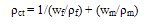 | (1) |
 | (2) |
3.2. Micro Hardness
- Micro-hardness measurement is done using a micro-hardness tester equipped with a square based pyramidal (angle 136° between opposite faces) diamond indenter by applying a load of 10 N.
3.3. Impact Test
- Low velocity instrumented impact tests are carried out on composite specimens. The tests are done as per ASTM D 256 using an impact tester. The pendulum impact testing machine ascertains the notch impact strength of the material by shattering the V notched (45º) specimen with a pendulum hammer, measuring the spent energy, and relating it to the cross section of the specimen. The standard specimen for ASTM D 256 is 60×10 × 4 mm3 and the depth under the notch is 2 mm. The machine is adjusted such that the blade on the free-hanging pendulum just barely contracts the specimen (zero position). The specimens are clamped in a square support and are struck at their central point by a hemispherical bolt of diameter 5 mm. The respective values of impact energy of different specimens are recorded directly from the dial indicator.
3.4. Scanning Electron Microscopy
- The surfaces of the specimens are examined directly by scanning electron microscope JEOL JSM-6480LV in the mode. The eroded samples are mounted on stubs with silver paste. To enhance the conductivity of the eroded samples, a thin film of platinum is vacuum-evaporated onto them before the photomicrographs are taken.
4. Result and Discussion
- The impact strength and physical properties of the composites are presented below. Also the steady state erosion behaviour and worn surface morphology discussions based on the SEM investigations are shown in the micrographs.
4.1. Density
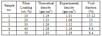
- Density is one of the most important factors determining the properties of the composites and it depends on the relative proportion of matrix and reinforcing materials. The theoretical and measured densities along with the corresponding volume fraction of voids are presented in Table 1. It may be noted that the composite density values calculated theoretically from weight fractions using Equation 1 are not in agreement with the experimentally determined values. The difference is a measure of voids and pores present in the composites or the void content is the cause for the difference between the values of true density and the theoretically calculated one.
|
4.2. Micro Hardness
- Surface hardness of the composites is considered as one of the most important factors that govern the erosion resistance. The measured hardness values of all the composites are shown in Figure 2. It is seen that with increase in the fiber loading the hardness value of all the composites increases. In case of composites with fiber loading up to 50 wt.-% gives higher value of micro- hardness are obtained as compared to 10 wt.-% composite. With the increase in fiber loading the formation of air bubbles and voids in composites decreases which causes the homogeneity in microstructure and affecting the mechanical properties. Oksman[12] reported clearly that inclusion of bamboo fiber in the epoxy matrix body results in improving the hardness of the composites although this improvement is marginal. This is because hardness is a function of the relative fiber volume and modulus[13].
 | Figure 2. Variation of Micro Hardness with different fiber loading |
4.3. Impact Strength
- Impact resistance is the ability of a material to resist breaking under a shock loading or the ability to resist the fracture under stress applied at high speed. Impact behavior is one of the most widely specified mechanical properties of the polymeric materials[14]. Results of impact test are shown in Figure 3.
 | Figure 3. Variation of Impact Strength with fiber loading |
4.4. Steady state Erosion
4.4.1. Influence of Impingement Angle
- Steady-state erosion rates as a function of impingement angle (α) are plotted in Figure 4.The erosion behaviour of materials is broadly classified in the literature as ductile (occurs at 15º-30º impact angle) and brittle (occurs at 90º) depending on the variation of erosion rate with impingement angle. Figure 4 show that the 50 wt.-% glass fiber reinforced composite exhibits maximum erosion rate and 30 wt.-% fibre reinforced shows the minimum erosion rate. This is due to that in 50 wt.-% glass fiber reinforced composites there is improper mixing of the fiber and matrix takes placed therefore the proper bonding between these two materials does not takes place i.e. the matrix does not cover the whole fibers, whereas in case of 30 wt.-% fiber reinforced composite the matrix and fibers mixing together properly i.e. matrix cover whole the fibers in the composites and bonding between these two materials is good. In the present study the maximum erosion rate occurs at 60º impingement angle and minimum at 30º and 90º impingement angles for all the composites. This clearly indicates that these composites respond to solid particle impact neither shows the brittle behaviour nor shows the ductile behaviour it purely shows semi-ductile behaviour.
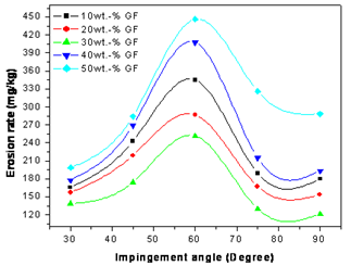 | Figure 4. Influence of impingement angle on erosion rates of fiber reinforced composites |
4.4.2. Influence of impact velocity
- The variation of erosion rate of fiber reinforced composites with impact velocity is shown in Figure 5. Erosion trials are conducted at five different impact velocities. It is quite clear from Figure 5 that steady-state erosion rate of the same composites increases with increase in impact velocity. It was observed that the composite with 30 wt.-% of short glass fibre is most resistant to erosion followed by the composites with 20, 10, 40 and 50 wt.-% fibre contents in decreasing order. The increase in erosion rate with impact velocity can be attributed to increased penetration of particles on impact as a result of dissipation of greater amount of particle thermal energy to the target surface. This leads to more surface damage, enhanced sub-critical crack growth etc. and consequently to the reduction in erosion resistance.
 | Figure 5. Influence of impact velocity on erosion rates of fiber reinforced composites |
4.5. Surface Morphology
- Morphologies of eroded surfaces of the composite samples are observed under a scanning electron microscope (SEM). From SEM observations of the eroded surfaces, it appears that composites under consideration exhibit several stages of erosion and material removal process. Figure 6 (a) shows very low removal of material at lower impact velocity (v=43 m/s) from the surface of composite i.e. the only local removal of matrix material takes place. As the velocity increase i.e. at higher velocity the large amount of matrix material takes off from the surface of composite and array of fibres is exposed to erosive environment as shown in the Figure 6 (b). Figures 6 (c-d) shows a portion of the composite surface eroded at an impingement angle of 60°. This is the case of maximum material loss due to impact erosion. The matrix material covering the fibre seems to be chipped off and removed by micro cutting or micro ploughing due to repeated impact of hard silica sand particles and thus craters are formed. The continuation of erosion by silica sand particle impacts resulted in damage to the interface between the fibers and the resin matrix. This damage is shown in Figures 6 (e) and f and characterized as the separation and detachment of broken fibers from the matrix material. It is well known that the fibers in composites subjected to particle flow, undergo breakage when subjected to bending. As we said above that there is a local removal of matrix material from surface of the impacted composite, which results in the exposure of the fibres shown in Figure 6 (b), this causes intensive debonding and breakage of the fibres, which are not supported by the matrix. This observed erosion damage is characterized by fibre–matrix debonding, multiple fibre cracking and material removal. The impingement of the erodent caused roughening of the surface of the material, especially in higher contact angles. In Figure 6 (g) and Figure 6 (h) the matrix shows multiple fractures and material removal and the exposed fibres are broken into fragments and thus can be easily removed from the worn surfaces. The broken fibre and fragments are mixed with the matrix micro-flake debris and the damage of the composite is characterized by separation and detachment of this debris.
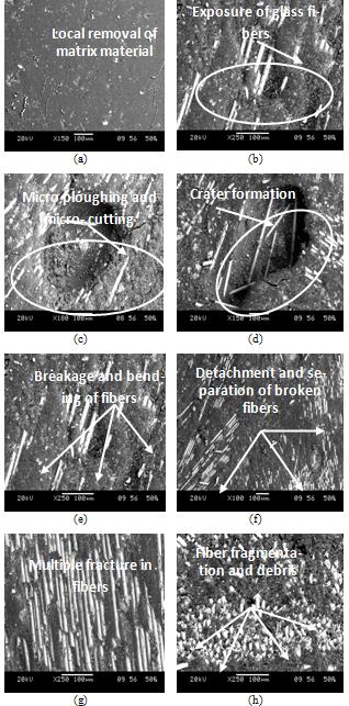 | Figure 6. SEM micrographs of the eroded glass-polyester composites |
5. Conclusions
- Solid particle erosion, physical properties and impact strength of short glass fiber reinforced polyester composites have been evaluated. Based on this the following conclusions are drawn.1. The composite with five different fiber loading (10, 20, 30, 40 and 50 wt.-%) reinforcing into polyester matrix are fabricated successfully with hand-lay-up technique. It is noticed that there is significant improvement in all the properties of composites with the increase in fiber loading.2. It is found that with increase in the fiber loading in polyester matrix the impact strength of the composites also increases. This increase in impact strength of the composites is due to the inclusion of glass fiber improves the load bearing capacity and the ability to withstand bending of the composites. Also the micro-hardness of the composites increases with increase in fiber loading in the polyester matrix. 3. In the steady state erosion process there is a great effect of impingement angle (α) impact velocity (v), fiber loading and erodent size on the erosion wear rate of the composites. The erosion rate is increases with increase in the impact velocity. The composite with 50 wt.-% fiber loading shows the maximum erosion rate and the composite with 30 wt.-% of fiber loading shows the minimum erosion rate i.e. the composite with 30 wt.-% fiber loading exhibits better erosion resistance property as compare to the others composite. In the present study the maximum erosion rate occurs at 60º impingement angle and minimum at 30º and 90º impingement angles for all the composites. This clearly indicates that these composites respond to solid particle impact neither shows the brittle behaviour nor shows the ductile behaviour it purely shows semi-ductile behaviour. 4. Wear surface morphology shows that the erosion process involves different mechanisms depending on the type and arrangement of fibre in the matrix. In the present study all the composites shows the semi-ductile behavior because peak erosion takes place at 60° impingement angle. For short glass fibre composite, severe deterioration of both fibre and matrix, micro-ploughing in the matrix, composite debonding, fiber chip off, fiber fragmentation and fibre-fracture were found out to be the characteristic features of damage in glass fibre.