-
Paper Information
- Next Paper
- Paper Submission
-
Journal Information
- About This Journal
- Editorial Board
- Current Issue
- Archive
- Author Guidelines
- Contact Us
American Journal of Materials Science
p-ISSN: 2162-9382 e-ISSN: 2162-8424
2012; 2(1): 1-4
doi:10.5923/j.materials.20120201.01
Micro-Structural Characterization of Si-SiC Ceramic Derived from C/C-SiC Composite
 Abstract
 Reference
 Full-Text PDF
 Full-text HTML
V. K. Srivastava
Department of Mechanical Engineering, Institute of Technology, BHU, Varanasi , 221005, India
Correspondence to: V. K. Srivastava, Department of Mechanical Engineering, Institute of Technology, BHU, Varanasi , 221005, India.
| Email: |  |
Copyright © 2012 Scientific & Academic Publishing. All Rights Reserved.
The main objective of the present work is to processing the porous Si-SiC ceramic by the oxidation of C/C-SiC composite. Phase studies are performed on the oxidized porous composite to examine the changes due to the high temperature oxidation. Further, various characterization techniques are performed on Si-SiC ceramic in order to study the material’s microstructure.
Keywords: Processing, Properties, C/C-SiC Composite, Carbon Fibre, Oxidation
Cite this paper: V. K. Srivastava, Micro-Structural Characterization of Si-SiC Ceramic Derived from C/C-SiC Composite, American Journal of Materials Science, Vol. 2 No. 1, 2012, pp. 1-4. doi: 10.5923/j.materials.20120201.01.
Article Outline
1. Introduction
- C/C-SiC composite has found to be extensive applications in the field of aerospace and aeronautics industry for rocket nozzles and re-entry thermal protection shields of space vehicles, in automotive industry as ceramic brake discs, heat insulating materials and various other structural applications, since the proposition of its low cost manufacturing methods by various researchers[1-3]. Further, SiC-based ceramics are known to exhibit excellent oxidation characteristics owing to the formation of a protective silica scale, which slows down the oxidation rate as long as the oxidation conditions remain those of the so-called passive oxidation regime of SiC. Significant degree of research is going on in development of porous material aimed for different applications. Some of the porous materials include graphite/carbon foam, ceramic foam, porous conducting paper for electrodes of fuel cells, etc. Silicon infiltrates into the segmentation cracks arising during pyrolysis of CFRP’s and forms layers of protective segments over the carbon fibers resulting in the retardation of oxidation of the C/C-SiC composite, when subject to the high temperature environments. However, the carbon fibers which run through the C/C-SiC laminate are not completely covered by the silicon carbide/free silicon in the longitudinal direction of the fibers [4]. The realization of the idea was also from the fact that there exist differences in the oxidation temperatures between carbon, silicon carbide and free silicon [5-7]. The above mentioned facts of the C/C-SiC composites are exploited in obtaining such a material. Hence, a controlled oxidation of the C/C-SiC composite in an oxidizing atmosphere should result in the oxidation of the carbon fibers only leaving behind a network of channels resulting from depletion of carbon throughout the entire composite, forming a highly porous structure [8,9]. Considering the oxidation of the carbon matrix, as well, the open porosity obtained should be significantly high [10,11]. The present work is aimed at the manufacture of novel material, styled as “Si-SiC porous ceramic”, derived from C/C-SiC composites, which exhibit superior performances over the conventional porous materials, and, perform its characterization.
2. Experimental Work
- The carbon fibers are stacked and impregnated with phenolic resin using hand laying procedures. The mould is then warm pressed, cured and post-cured in a vacuum oven to obtain the carbon fiber reinforced plastic composites (CFRP). The open porosity of the matrix is nearly about 1% at this step.
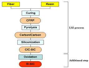 | Figure 1. Steps involved in the manufacture of Si-SiC porous ceramic. |
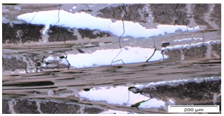 | Figure 2. Heterogeneous structure of C/C-SiC obtained by optical microscope. |
3. Results and Discussion
3.1. Thermo-gravimetric Analysis
- The samples were sized to about 6mm*6mm*3mm dimensions and were subjected to controlled heating/cooling under dynamic air flow conditions of 5.0 liter/min in a thermo-gravimetric setup.
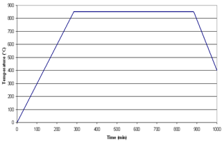 | Figure 3. Time – Temperature curve (TTC) followed for oxidizing C/C-SiC composite. |
3.2. Image Analyses
3.2.1. Optical Microscopy
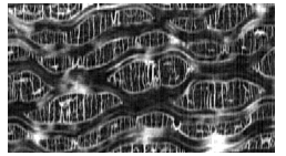
- Extensive optical studies were performed on the composites both before and after oxidation. Since the microstructure of the C/C-SiC composites is evident, the discussion here would be restricted to only oxidized samples and images of interest. The analyses of the samples were performed on a light microscope at 10x magnification with computer interfacing. Fig.4 shows that the carbon fibers have all oxidized except for a few traces which are due to the single carbon fibers getting siliconized which cannot be oxidized as they are covered by the protective layer of silicon carbide or have completely transformed to SiC. But, the overall structure of the composite is formed with the silicon carbide walls being well developed between fiber bundles [3,5]. The large white patch at the centre of the image is the presence of free silicon which is surrounded by a thin layer of silicon carbide. The image shows relatively non uniform segments of pores that are formed following oxidation. The silicon carbide walls are highly random in nature which branch up in between the fiber bundles and not uniformly separated. Further, the number of single fiber siliconizations is significantly higher. The short fiber samples show a highly random structure of pores. Adjusting the focus of the microscope to different depths of focus showed indications of the closure of pores with the end of the fiber bundle (small depth pores), as shown in Fig.4. A few thin walls of SiC are due to the large number of localized fiber siliconizations. This shows that the silicon walls formed are more uniform and extend completely between the fiber bundle in case of resol resin derived samples causing uniform segments of pores, which is highly essential for the performance of the porous material when applied in filter technology[7]. However, novolak resin derived samples show higher amount of single fiber siliconizations which yield a higher surface area, a property desirable for catalyst
3.2.2. Scanning Electron Microscopy (SEM)
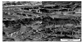
- The SEM images of the three samples were taken in secondary electron mode as well as the back scatter electron mode. The samples used for the analysis were obtained by subjecting the C/C-SiC composites to oxidation temperatures of 1200°C for duration of 2 hours. This is resulting from the wider segmentation cracks formed during the pyrolysis stage especially in case of novolak resin based ceramics [9]. Fig. 6 shows a random arrangement of SiC walls that are being formed due to the randomness of the fiber arrangement itself in case of short fiber derived ceramics. The pores sizes are relatively smaller than the woven fabric based ceramics. Figs. 5 & 6 indicate a uniform structure obtained by using the woven carbon fibers. The images also indicate a high degree of porosity of the samples. Further, it can be seen clearly in the back scatter electron image of Fig. 5 patches of silicon being enclosed by the silicon carbide.
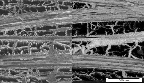 | Figure 5. SEM image showing the random structure of SiC walls derived from oxidation of novolak resin, twill weave based C/C-SiC composite. |
 | Figure 6. SEM image showing the random structure derived from oxidation of novolak resin, short fiber weave based C/C-SiC composite. |
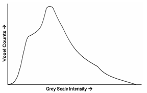 | Figure 7. Non-evaluable gray scale histogram type obtained for the highly porous Si-SiC ceramic |
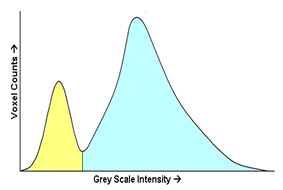 | Figure 8. Evaluable gray scale histogram type for a typical porous material. |
3.2.3. Computer Tomography Analysis
- The 3-dimensional reconstruction of the oxidized samples using Computed Tomography (CT) setup interfaced with 3-dimensional image analysis software. The samples were analyzed for the open porosity and the pore size distribution. The gray scale histogram obtained for the porous Si-SiC samples is shown in the Fig. 7. For the porous material to be evaluable, a gray scale histogram with a nature similar to Fig. 8 should be obtained with two well defined peaks corresponding to air and material respectively. The area under the curve corresponding to the gray scale intensities of air gives the porosity present in the area of interest. As a result, for the grey scale histogram obtained for the porous Si-SiC samples, such a demarcation line between the air and the material was not possible, hence, rendering the histogram non-evaluable. The reason for this shortcoming can be attributed to the resolving power of the imaging setup and the incapability in the image analysis software [5,10]. Therefore, the quantitative measurement for porosity and its distribution was not possible. However, qualitative analysis for porosity was done on few of the samples. An investigation of the porous Si-SiC ceramic (oxidized novolak resin, twill weave derived) for different C/C-SiC sample along different cross sections across the carbon fiber stacking direction (Fig. 9) showed well developed walls of silicon carbide that are formed running along the fiber tow direction. Even though the walls are not continuous along the tow direction, the average number of walls that are present across any section of the fiber tow is almost the same [11]. Fig. 10 shows one of the cross sectional images taken along the fiber alignment direction revealing the through network of channels that are formed with the channels running through the fiber tow.
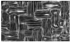 | Figure 9. Image of the developed SiC wall across the carbon fabric. |
 | Figure 10. Image of the developed channel along fibre direction. the carbon fabric. |
4. Conclusions
- The results were consistent when image analyses techniques like optical microscopy, SEM and CT were used. The optical microscopy and the back scatter image in SEM showed silicon covered by silicon carbide. CT did not yield quantitative results due to some inherent problems in the data acquisition and processing setup. However, a qualitative analysis showed well developed channels formed by the oxidation of carbon fiber tows. Woven fabrics are preferred as they have an ordered structure and the pores formed are more uniform with the network of pores well developed in comparison to the short fibers. Also, resol phenolic resins gave uniform and symmetrical structures of SiC walls formed through the fiber bundle, unlike in case of novolak resin based composites. Further, the oxidation temperature has a pronounced effect up to around 900°C.
ACKNOWLEDGEMENTS
- Author is thankful to Department of Material Processing Engineering, University of Bayreuth, Germany and Department of Mechanical Engineering, Institute of Technology, BHU, Varanasi-221005, India for their all supports.
References
| [1] | W. Krenkel, Cost Effective Processing of CMC Composites by Melt Infiltration (LSI-Process), Ceramic Engineering and Science Proceedings (Ed: American Ceramic Society), vol. 22(3), pp. 443-454, 2001 |
| [2] | F.J. Schulte, A. Zern, J. Mayer, M. Rühle, M. Frieß, W. Krenkel and R. Kochendörfer, The Morphology of silicon carbide in C/C-SiC composites, Mater Sci Eng- A, pp.146-152, 2002 |
| [3] | W. Krenkel, R. Renz and B. Heidenreich, Lightweight and wear resistant CMC brakes, Ceramic Materials and Components for Engines (Eds.: J. G. Heinrich, F. Aldinger), WILEY-VCH, Weinheim, Germany, pp. 63-67, 2001 |
| [4] | W. Krenkel, Designing with C/C-SiC composites, in Advances in Ceramic Matrix Composites IX (Eds.: N.P. Bansal, J.P. Singh, W.K. Kriven, H. Schneider), Ceram. Trans. Vol 153, pp. 103-123, 2003 |
| [5] | W. Krenkel, From Polymer to Ceramics: Low cost manufacturing of ceramic matrix composite materials mol. Cryst. and Liq. Cryst. Vol. 354(1),pp. 353-364, 2000 |
| [6] | L.P. Zawada, R.S. Hay, S.S. Lee and J. Staehler, Characterization and high-temperature mechanical behavior of an oxide/oxide composite J. Am. Ceram. Soc. Vol. 86(6), pp.981-990, 2003 |
| [7] | C.G. Levi, J.Y.Yang, B.J. Dalgleish, F.W. Zok and A.G. Evans, Processing and performance of an all-oxide ceramic composite J. Am. Ceram. Soc. Vol. 81(8), pp.2077-2086, 1998 |
| [8] | R. Weiss R, Carbon fibre reinforced CMCs: manufacture, properties, oxidation protection, High Temperature Ceramic Matrix Composites (Eds.: W. Krenkel, R. Naslain, H. Schneider), WILEY-VCH, Weinheim, Germany, pp. 440-456, 2000 |
| [9] | F. Christin, Design, Fabrication and application of thermostructural composites (TSC) like C/C, C/SiC and SiC/SiC composites, Advanced Engineering Materials, vol. 4(12), pp. 903-912, 2002 |
| [10] | R. Kochendörfer and N. Lützenburger, Applications of CMCs made via the liquid silicon infiltration (LSI) technique, High Temperature Ceramic Matrix Composites (Eds.: W. Krenkel, R. Naslain, H. Schneider), WILEY-VCH, Weinheim, Germany, pp. 277-287, 2001 |
| [11] | V.K. Srivastava, W. Krenkel, V.J.A. D’Souza and H.W. Mucha, Manufacturing, Analysis and Modelling of Porous Si-SiC Ceramics Derived by Oxidation from C/C-Si-SiC Composites, J. Ceram. Sci. Techno, vol 2 (2) pp. 111-118, 2011 |