-
Paper Information
- Next Paper
- Previous Paper
- Paper Submission
-
Journal Information
- About This Journal
- Editorial Board
- Current Issue
- Archive
- Author Guidelines
- Contact Us
American Journal of Materials Science
p-ISSN: 2162-9382 e-ISSN: 2162-8424
2011; 1(2): 123-127
doi: 10.5923/j.materials.20110102.20
Sem Studies of Tensile Fractured Surfaces of Expanded Graphite/Acrylonitrile/Methyl Methacrylate Nanocomposites Prepared via in-Situ Polymerization
 Abstract
 Reference
 Full-Text PDF
 Full-Text HTML
Solomon C. Udensi 1, Lebe. A. Nnanna 2
1Department of Physics, Federal University of Technology Owerri, Owerri, Imo State, P.M.B. 1526, Nigeria
2Department of Physics/Electronics, Abia State Polytechnics Aba, Abia State, P. M. B. 7166, Nigeria
Correspondence to: Solomon C. Udensi , Department of Physics, Federal University of Technology Owerri, Owerri, Imo State, P.M.B. 1526, Nigeria.
| Email: |  |
Copyright © 2012 Scientific & Academic Publishing. All Rights Reserved.
Expanded graphite/Acrylonitrile/methyl methacrylate nanocomposites of different weight contents (0 to 5 wt. %) of Expanded Graphite (EG) were prepared via polymerization and examined for their yield and failure behaviours under uniaxial stress state. The failure mechanism shows transitions from sheared to crazed states as the volume contents of EG were increased. SEM photomicrographs also confirmed the brittle to ductile microstructural transitions of the nanocomposites. The toughness of the nanocomposite with 3 wt. % EG was optimum, and the process of crack growth which led to this high toughness could be seen. The decisive parameter which influenced the fracture data of EG/AN/MMA nanocomposites was found to be volume fraction of EG and interfacial adhesion of AN/MMA matrix and EG particles.
Keywords: Expanded Graphite (EG), Nanocomposites, Sheared Stress, Crazed Stress, Deformation
Cite this paper: Solomon C. Udensi , Lebe. A. Nnanna , "Sem Studies of Tensile Fractured Surfaces of Expanded Graphite/Acrylonitrile/Methyl Methacrylate Nanocomposites Prepared via in-Situ Polymerization", American Journal of Materials Science, Vol. 1 No. 2, 2011, pp. 123-127. doi: 10.5923/j.materials.20110102.20.
Article Outline
1. Introduction
- Polymeric nanocomposites are multi-phased solids, where one of the phases has one, two, or three dimensions less than 100 nm[1]. That is to say that the solid (nanocomposite) is derived from a bulk matrix of polymer and nano-dimensional materials/phases, which exhibit dissimilar properties, as a result of there dissimilar chemical compositions. These dissimilarities explain to a large extent, the differences observed in mechanical, electrical, optical, thermal, etc properties of nanocomposites when compared to those of the component materials. One of such nano-dimensional materials used as filler is graphite nanoplatelets. Graphite nanoplatelets have grown in prominence[2,3] because of there ability to easily expand and/or exfoliate with the application of heat within its heat resistant range of -200 to 3000℃ [4]. There are very few literatures, to my knowledge, which have reported any result(s) on the effect of included stress sites on the mechanical properties of in situ prepared polymeric nanocomposites.This study is propitious, if the longevity of our light weight nanocomposites is to be guaranteed and applied in fields such as aviation, windmill, audio industries etc. where mechanical strength, toughness, etc of materials are pre- requisite for performance. One useful characterization tool which has been of help to scientists in studying the effect of minuscule cracks, voids and other tiny defects is the scanning electron microscope (SEM). The aim therefore, is to report the results as observed using SEM to study the two main deformation mechanisms- shear yielding and crazing[5] in (EG/AN/MMA) nanocomposites prepared via in-situ polymerization.
2. Experimental
2.1. Materials
- Graphite power (SP-1 grade) from Bay carbon Incorporated containing 1 ppm of Silicon. Sulphuric acid and concentrated nitric acid from Sigma Aldrich were used as intercalants in the graphite powder, in order to aid exfoliation. Other materials from Sigma Aldrich include: anhydrous ethanol (99.9% vol.), methyl methacrylate (MMA) monomer (lot no. 180882) and acrylonitrile (≥ 99.0%) monomer (lot no. 110213). Monomers MMA (density 0.936g/mL) and AN (density 0.8g/mL) were mixed in the ratio of 1:1. 1 wt % of expanded graphite (EG) was added to the mixture, which was maintained at 65℃ and stirred for about 3 mins, in order to achieve good dispersion of EG. 2.5 wt % Benzoyl Peroxide (BPO), an initiator was then added to the mixture and the beaker covered with parafilm material. The stirring was continued for another 3mins, during which the liquid mixture started coagulating. The thermosetting mixture was then cast into an iron mould with cavities measuring 50mm x 5mm x 2.02mm, kept overnight in an oven, at a temperature of 50℃. Polymerization was allowed to run to completion for another 18 hrs in this oven, at this temperature (50℃).The “dog-bone” shaped samples obtained from these moulds were then prepared for scanning electron microscope (SEM) and tensile testing, in order to investigate the microstructure of our new composite (EG/AN/MMA) with that of 0 wt% EG/AN/ MMA nanocomposite.Also 2 wt%, 3 wt%, 4 wt%, and 5 wt% EG were added to the 1:1 MMA, AN and BPO mixture. The same procedure was followed to obtain samples for testing and comparison. The tensile tests were performed at room temperature to conform with ISO 527-1 standard for measuring rigid plastics using Zwick Z100 static testing machine with in-built ( testXpert® II ) software and a digital clip-on extensometer. After these tests, fracture analyses of the faces of the fragmented specimens were done using Zeiss scanning electron microscope (ultra high resolution). The surfaces of the sample were gold plated to aid the SEM analysis. The failure mechanisms of the samples were studied by direct observation of the structures of the tensile fractured surfaces.The gauge lengths, widths and thicknesses of the samples were measured using callipers and recorded (i.e. 50mm x 5mm x 2.02mm). In order to make the samples insensitive to transverse forces, a 5KN load cell whose operation is based on the principle of axial/rotational symmetry, and most suitable for measuring plastics, was attached to the Zwick Z100 static testing machine for this work. Five different tests, for each sample/composite was carried out for this study.
3. Results and Discussion
- It is a well-known fact that the mechanical properties of nanocomposites are dependent on the type of filler used, in our case expanded graphite. The factors that must be emphasized upon are the filler- to - EG-AN/MMA) interfacial adhesion and orientation[6]. Also the surface area/volume ratio of the filler is another vital property of reinforcements (fillers)[7-11].Low strength usually results from weak interfacial regions, consequently leading to reduced efficiency in stress transfer and ultimately a premature failure of the material under test. Therefore, addition of fillers to any given polymer matrix usually does not necessarily result in increased tensile properties of the composite. Factors that determine the quality of interfacial bond include; filler/fibre aspect ratio, nature of filler and polymer matrix, and processing technique applied during treatment of fibre and/or polymer[12]. Figures' 1 and 2 show the tensile properties of the composite- that is the tensile strength and the ultimate elongations. Addition of 1 wt. % to 4 wt. % EG improved the tensile properties of the matrix. The composite with 3 wt % showed the highest strength and ultimate elongation. Composites with 2 wt % and 4 wt. % EG in them showed approximately same strength but different ultimate elongation, because in 2 wt % the matrix is not well saturated and so possesses points which constituted dislocation sites. In the composite with 4 wt % EG, the property that accounted for more elongation was the proper alignment of the EG in the matrix. However, increment to 5 wt % led to least adhesion between EG and AN/MMA matrix, thereby lowering the original tensile properties of the matrix with any EG. This is also attributed to horizontal orientation of EG in the matrix, compared to the line of tension.
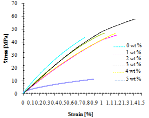 | Figure 1a. Stress versus strain curve for various weight percent EG in AN/MMA matrix |
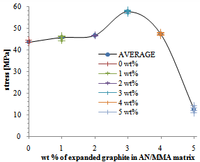 | Figure 1b. Stress versus weight percent EG in AN/MMA matrix |
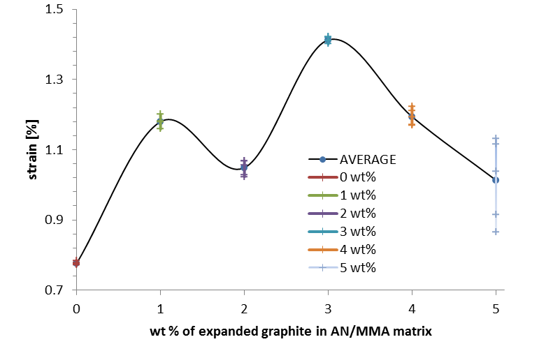 | Figure 2. Strain versus weight percent EG in AN/MMA matrix |
 | Figure 3a. 0 wt. % |
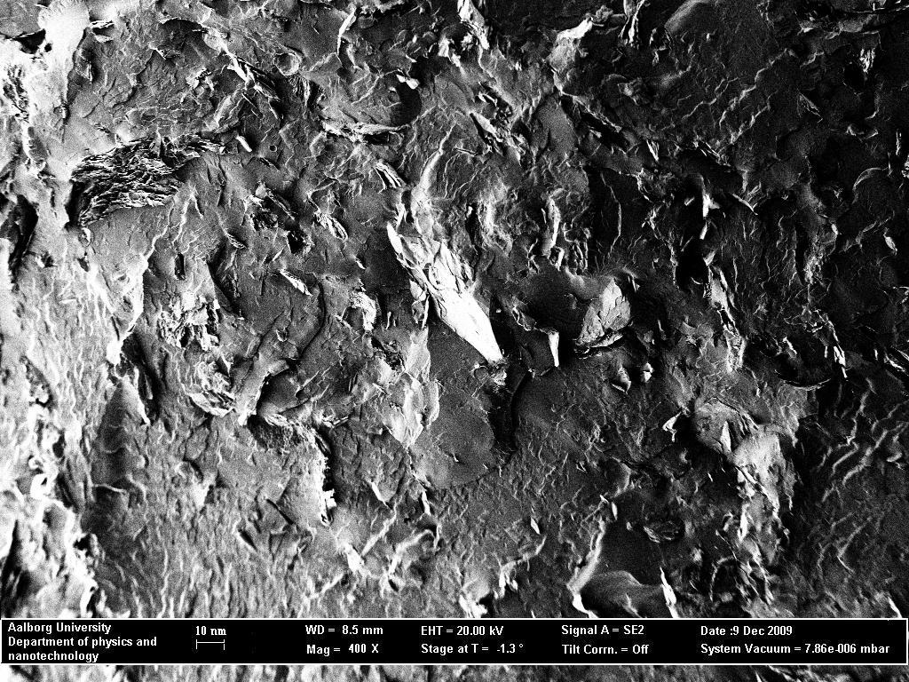 | Figure 3b. 1wt. % |
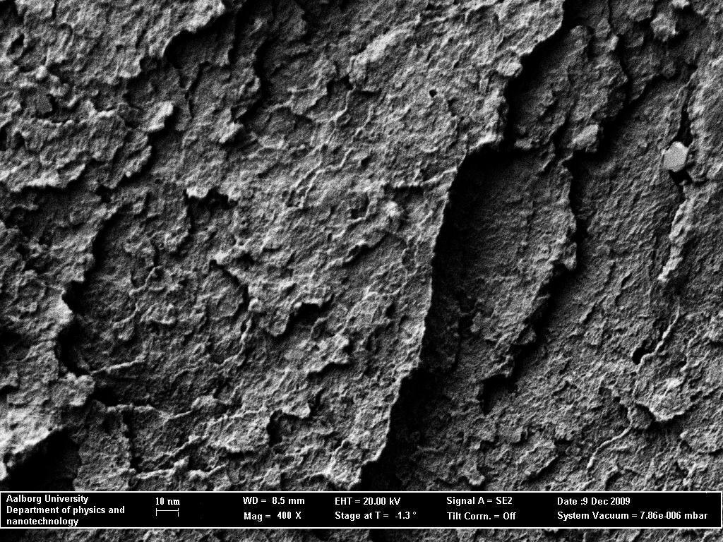 | Figure 3c. 2 wt.% |
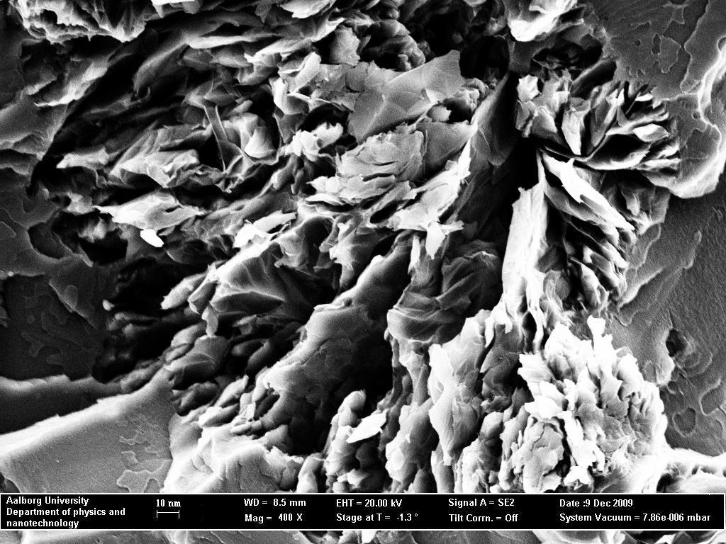
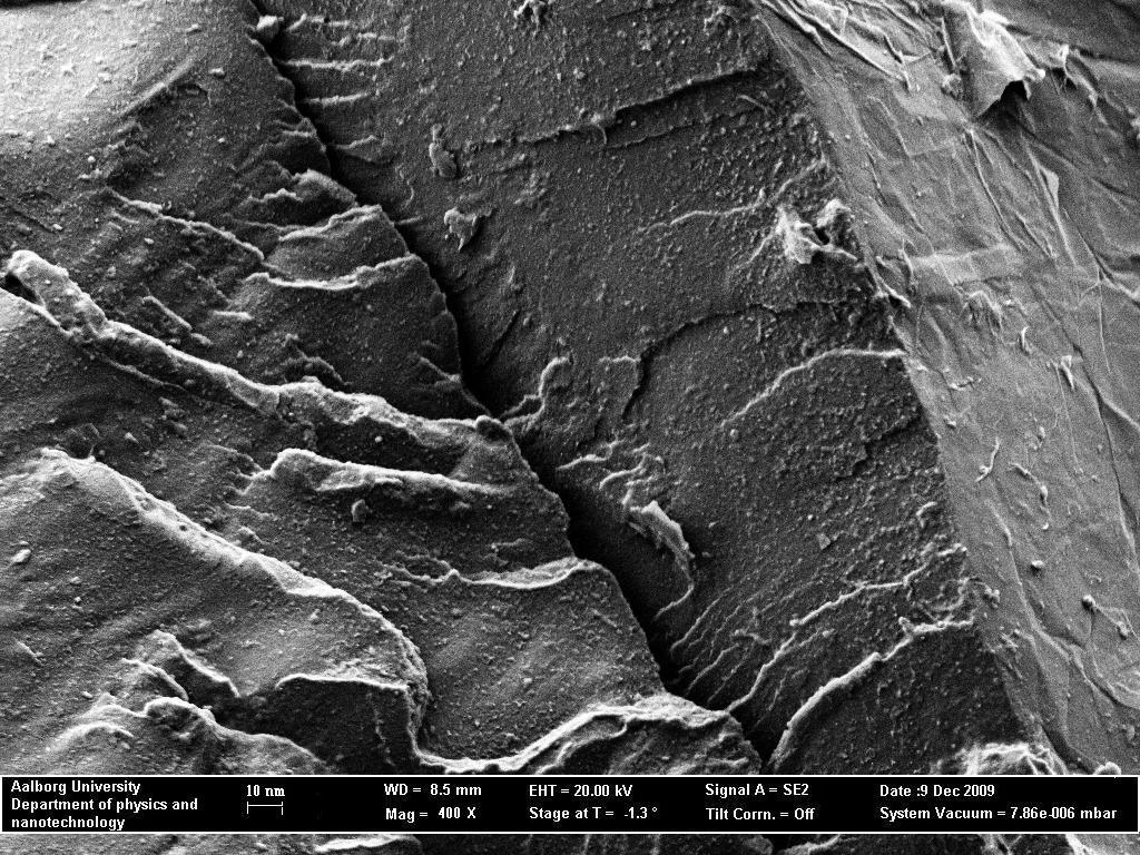 | Figure 3d. 3wt.% |
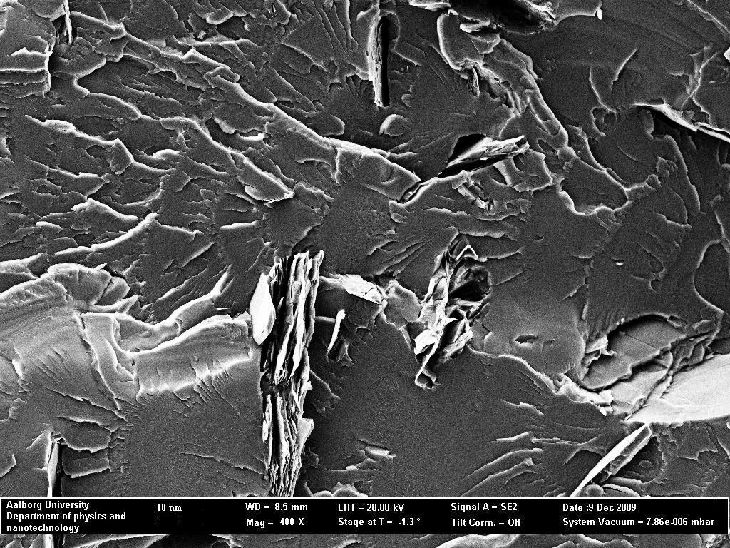 | Figure 3e. 4wt.% |
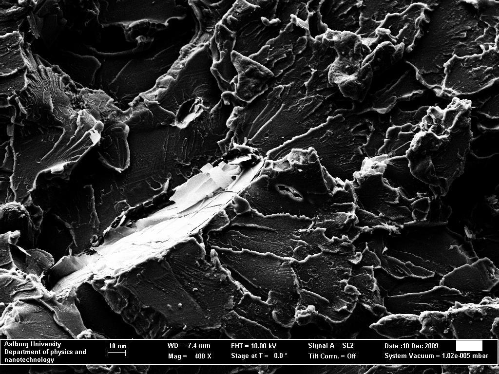 | Figure 3f. 5wt. % |
4. Conclusions
- In this paper, the study of fractured tensile surface of in situ prepared EG/AN/MMA composite is reported. We found out that• The SEM image of the fractured surface of 3 wt% EG/AN/MMA nano-composites showed that the high ultimate tensile strength, toughness and the high fracture strength were as a result of good filler-to-matrix (i.e. EG-to-AN/MMA) adhesion, dispersion, and strength of graphite nanoplatelets. This imparted into the composite a good matrix to filler load transfer. This image also showed increased shear regions thought to improve the ductility of the matrix (AN/MMA). It also supported the views that both shear stress and hydrostatic stress exist in polymers, and could transit from one stress state to another.• There was a transition from the glassy matrix to a somewhat ductile nanocomposite, with maximum ductility occurring on addition of 3 wt % EG.• Overloading of our matrix with more than 3 wt % EG resulted on misalignment and different orientation of EG in the matrix (see figs 3e and 3f). This reduced the matrix- to- filler load transfer of the specimens’ 4- and 5 wt %.
ACKNOWLEGDEMENTS
- The authors are grateful to the department of Physics and nanotechnology, Aalborg University Denmark, for the characterization of our sample and to Prof Donghung Yu of the Chemistry department of the same University for some insightful sessions we had together.