-
Paper Information
- Next Paper
- Previous Paper
- Paper Submission
-
Journal Information
- About This Journal
- Editorial Board
- Current Issue
- Archive
- Author Guidelines
- Contact Us
American Journal of Materials Science
p-ISSN: 2162-9382 e-ISSN: 2162-8424
2011; 1(2): 113-122
doi: 10.5923/j.materials.20110102.19
Influence of Zirconia Incorporation on the Mechanical and Chemical Properties of Ni-Co Alloys
 Abstract
 Reference
 Full-Text PDF
 Full-Text HTML
Meenu Srivastava , A Srinivasan, V K William Grips
Surface Engineering Division, Council of Scientific and Industrial Research, National Aerospace Laboratories, Bangalore, 560017, India
Correspondence to: Meenu Srivastava , Surface Engineering Division, Council of Scientific and Industrial Research, National Aerospace Laboratories, Bangalore, 560017, India.
| Email: |  |
Copyright © 2012 Scientific & Academic Publishing. All Rights Reserved.
Ni-Co-ZrO2 nano-composites are electrodeposited from sulphamate electrolyte and a comparison is made with Ni-ZrO2 in terms of structure and properties. The Co content in the coatings is in the range of 10-80wt%. The deposition conditions like current density, pH are optimized in terms of microhardness and amounts of ZrO2 incorporated. The microhardness studies revealed that the maximum hardness is exhibited by Ni-28Co-2ZrO2 composite. The FESEM study showed a change in morphology from polyhedral to ridge with increase in Co content from 10 to 80wt%. A change in crystal structure from fcc to hcp is also seen. The effect of annealing treatment in terms of microhardness is studied by subjecting the composite electroforms to 800℃. The Co rich composite exhibited better stability compared to Ni rich composites. Ni-28Co-2ZrO2 composite exhibited better immersion corrosion resistance while, Ni-ZrO2 composite displayed better electrochemical corrosion resistance. The wear studies showed that Ni-10Co-2ZrO2, Ni-28Co-2ZrO2 composites showed better resistance. Thus, it is seen that the coatings can be tailored to suit various applications.
Keywords: Metal matrix composites, Ni-Co-ZrO2, Tribology, Wear, Corrosion, Electrochemical Study
Cite this paper: Meenu Srivastava , A Srinivasan, V K William Grips , "Influence of Zirconia Incorporation on the Mechanical and Chemical Properties of Ni-Co Alloys", American Journal of Materials Science, Vol. 1 No. 2, 2011, pp. 113-122. doi: 10.5923/j.materials.20110102.19.
Article Outline
1. Introduction
- Corrosion and wear destroy national wealth in multibillion dollar range annually. Modern high performance components are subjected to extreme temperatures and mechanical stress, and thus require surface protection against high temperature and mechanical wear and tear. A highly versatile and low cost technique must be selected to apply protective coatings, one such technique is electroplating.1 Composite electroplating involves the co-deposition of insoluble metallic or non-metallic compounds in a metal or alloy matrix. Such composite coating features the properties of both the matrix and the dispersed phase. The coatings are called as metal matrix composites (MMC) when the matrix involved is a metal. Composite coatings comprising of various dispersed phases like SiC, Si3N4, Al2O3, CeO2, TiO2, YSZ etc have been developed for diverse applications.2-10 The composite system considered in the present study comprises of Ni-Co alloy as the matrix. The benefit of choosing Ni-Co alloy as matrix lies in the fact that alloying of Ni with Co strengthens it by forming a solid solution which helps to improve wear, corrosion resistance and also improves the high temperature properties.11,12 The dispersed phase chosen is zirconia ZrO2, as it is known to possess excellent properties such asmechanical strength, chemical inertness, thermal stability, wear and corrosion resistance.13 Its good thermal matching with metals makes it suitable for protective coatings.14,15 It is also a promising constituent present in the transition metal based catalysts used in exhaust gas purifying devices.16 Depending on its crystalline structure it can be an insulator used as high resistance ceramic or an n-type semiconductor.15 ZrO2 exists as a polymorph, namely cubic, tetragonal and monoclinic.17 The effect of incorporation of ZrO2 in Ni matrix has been extensively reported.13,18-24 Reddy et al have reinforced tetragonal ZrO2 in Ni matrix by pulsed electrodeposition. A 16% increase in microhardness of the composite has been reported.23 The composite on annealing (50-200℃) showed an increase in the microhardness followed by a substantial decrease upto 300oC. Effect of heat treatment on the incorporation of ZrO2 in Ni-Co matrix has not been studied much.25 Zhang et al have reported brush plating of Ni-Co-ZrO2 composite coating to repair the wear surface of the die casting dies of H13.The coating improved the surface hardness, wear resistance and oxygen resistance of dies.The present study is aimed at incorporating ZrO2 nano-particles in Ni-Co alloy matrices by electrodeposition method, and studying its influence on the thermal, mechanical and chemical properties.
2. Experimental
- The Ni/Ni-Co-ZrO2 nano-composites were electroformed from a conventional additive free sulphamate electrolyte of composition Nickel sulphamate 275g L-1, nickel chloride 6gL-1, boric acid 30gL-1 and SLS 0.2gL-1. Co was added as cobalt sulphamate and the additions were made so as to obtain Co content in the range of 10-80wt%. ZrO2 particles of size 20-30nm and monoclinic crystal structure were procured from M/s Nanostructured and Amorphous Materials, USA were used in this study. Particle content of 25gL-1 was dispersed in the electrolyte by magnetic stirring for a period of 16hrs prior to electrodeposition. The Ni-Co-ZrO2 composites were deposited galvanostatically under ambient conditions using optimized conditions of pH 4.0 and current density 0.8Adm-2. The coating was deposited on a mild steel substrate (cathode) of plating dimension 0.05mX 0.0375m using Ni sheet as anode of size 0.05mX0.05m. During the process of electrodeposition, the ZrO2 nano-particles were kept under suspension by magnetic stirring at a speed of 400rpm. The composite coatings were prepared metallographically and subjected to microhardness testing. The hardness was tested using the Knoop’s indenter (Buehler Microhardness tester Micromet 100) employing a load of 0.050kgf. The readings reported are the average of various measurements performed at different locations. The uniformity of ZrO2 distribution was analyzed using optical microscopy. The surface morphology of the coatings was studied using Field Emission Scanning Electron Microscope (FESEM), Carl Zeiss Supra 40 VP and ZrO2, Co content in the coatings was determined using Energy Dispersive X- ray analysis (EDX).The crystal structure and the phases were identified using X-ray diffraction (XRD) studies. The crystallite size of the coatings was determined using Scherer formula D=Kλ(βcosθ)-1 where, K is the Scherrer factor ≈1, D the crystallite size, λ the incident radiation wavelength, β is the integral breadth of the structurally broadened profile and θ is the angular position. 26 The thermal stability of the coatings was studied by subjecting the composite electroforms to isothermal annealing at temperatures ranging from 200℃ - 800℃ in intervals of 200℃ for a duration of 1 hour. The thermal stability has been expressed in terms of microhardness. The corrosion resistance of the coatings was determined by immersion method and also by electrochemical polarization technique. The immersion test has been performed by immersing the composite electroforms in 3.5% NaCl medium for 168hrs and the corrosion rate is expressed in terms of weight loss. A comparison was made with polarization and electrochemical impedance studies. These studies were carried out in a conventional three-electrode corrosion cell using a CHI604 2D (CH Instruments) test system. In the tests, specimen of area 1cm2 was exposed to the electrolyte (3.5% NaCl).The saturated calomel electrode was used as a reference, and platinum served as a counter electrode. The tests were performed under room temperature conditions. Prior to the experiment the samples were immersed in the electrolyte for 45mins to attain the open circuit potential (OCP) or steady state potential. After the stabilization of OCP the upper and lower potential limits were fixed to ± 200mV with respect to the OCP for carrying out the polarization studies. The Impedance measurements were performed in the frequency range of 10m Hz to 100 kHz and an amplitude of 10mV was applied on the OCP. All the measured data are presented as Nyquist and Bode plots. The wear resistance of the coatings has been analyzed under dry sliding conditions using Pin-on-disc wear tester (DUCOM India) and wear rate is expressed in terms of wear volume loss. The wear testing conditions are discussed in detail elsewhere.27 The volumetric wear loss V was determined using the equation: V = πh2 (r – h/3) 17 where r is the radius of the hemispherical pin and h is the wear height loss of the pin.
3. Results and Discussion
3.1. Ni-ZrO2 Co-deposition
- The deposition conditions were optimized with reference to Ni-ZrO2 composite coating in terms of microhardness. The pH was varied in the range of 2.5 to 4.5 and the current density in the range of 0.8 to 6.4Adm-2. The variation in microhardness and the extent of ZrO2 incorporation (Vol %) in the coating with respect to pH are shown in Figure1.
 | Figure 1. Correlation between pH and Microhardness, Vol % of ZrO2 incorporated in the coating |
 | Figure 2. Influence of current density on Microhardness and Vol% of ZrO2 incorporated in the coating |
|
3.2. Surface Morphology and Structure of Ni-ZrO2 Composite
- The amount of ZrO2 incorporated in the Ni-ZrO2 nano- composite electroforms was seen to be about 2wt% by EDX analysis. Wang et al have reported 2.70wt% of nano ZrO2 (10-30nm) incorporation in Ni matrix obtained by electrodeposition from a Watt’s bath.21 Simunkova et al have reported higher (9wt%) incorporation of 200nm size ZrO2 particles in Ni matrix compared to 40nm size particles (3wt%).8 Thus, other researchers have also obtained similar amount of nano ZrO2 particle incorporation in Ni matrix. The mechanism of ZrO2 incorporation has been reported by Wang, Benea et al.21,18 The SEM micrograph depicting the surface morphology of the composite electroforms is shown in Figure3. It is seen from Figure3a that agglomerates of nano ZrO2 particles are distributed on the surface of pyramidal shaped Ni crystallites. A similar morphology of ZrO2 agglomerates non-uniformly distributed throughout the Ni matrix has been reported by Hou et al.20
 | Figure 3. Surface morphology of (a) Ni-ZrO2composite coating; Insert shows the cross-sectional optical micrograph (b) Ni-10Co-ZrO2, (c) Ni-28Co-ZrO2 and (d) Ni-80-ZrO2 composite coatings; Insert shows the cross-sectional optical micrograph |
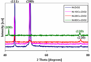 | Figure 4. X- ray diffractogram of (a) Ni-ZrO2, (b) Ni-10Co-ZrO2, (c) Ni-28Co-ZrO2 and (c) Ni-80-ZrO2 composite coatings |
3.3. Ni-Co-ZrO2 Co-Deposition
- Nano ZrO2 particles were incorporated in various Ni-Co alloy matrices. The amount of Co incorporated in the composite coatings was in the range of 10-80wt%. The amount of ZrO2 incorporated in the coatings remained a constant at 2wt% for Co content of 10-28wt%. For a Co content of 80wt% the amount of ZrO2 particles incorporated increased to 5wt%. Thus, an increase in Co content in the coating has resulted in an increase in ZrO2 incorporation. This shows that cobalt has better wettability for the particles compared to Ni. Similar observation has been made by the authors for other inert particles like SiC, Si3N4. 27,2 A comparison in the microhardness of Ni-Co alloys and Ni-Co-ZrO2 composite coatings is depicted in Figure5.
 | Figure 5. Variation in Microhardness with change in cobalt content in the coating |
3.4. Influence of Annealing Treatment on Microhardness
- The influence of annealing temperatures on the microhardness of Ni-ZrO2 and Ni-Co-ZrO2 nano-composites is shown in Figure 6. It is seen from the figure that the trend followed by the Ni and Ni-Co composites is similar to that of plain Ni and Ni-Co alloy coatings. The microhardness of Ni-2ZrO2 nano-composite is stable upto 400oC with no significant change in the values. The variation in microhardness of Ni-ZrO2 coatings with annealing temperature has also been studied by Reddy et al.23 They have observed an initial rise in the values upto 200oC followed by a drastic reduction at 300oC and subsequently a slow but continuous decrease at 600oC. The cause for the difference in behaviour between Reddy’s and present study is, the composite studied by former is pulsed co-deposited and the ZrO2 particles have tetragonal crystal structure 23 while, the deposition in the present study is direct current deposition and the particles have monoclinic structure. The microhardness of Ni-10Co- 2ZrO2 composites is higher than that of Ni-2ZrO2 composite.
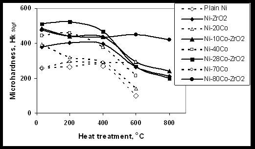 | Figure 6. Influence of temperature on the microhardness of Ni-ZrO2 and Ni-Co-ZrO2 composite coatings |
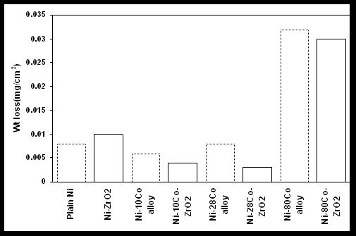 | Figure 7. Comparative weight loss of Ni-ZrO2 and Ni-Co-ZrO2 composites after immersion in 3.5%NaCl for 168hours |
3.5. Corrosion Behaviour
3.5.1. Immersion Corrosion
- The corrosion rate expressed in terms of weight loss on immersion in 3.5%NaCl is shown in Figure 7. It is seen from the figure that the weight loss of coating on immersion in NaCl is marginally less for the ZrO2 incorporated Ni-Co composites compared to Ni-Co alloy coatings. In other words, the corrosion resistance of the composite coatings is better, although to a smaller extent, compared to the plain coatings. It is also seen that the weight loss of Ni-28Co- ZrO2 composite is less compared to Ni-ZrO2 and other Ni-Co-ZrO2 composite coatings. Thus, it can be concluded that the corrosion resistance of Ni-Co alloy and the composite possessing Co content close to 25 ± 5wt% is better compared to plain Ni, its composite and other Ni-Co alloys, their composites. Similar observation for the Ni-Co alloys has been observed by the authors in earlier studies using Potentiodynamic polarization and Impedance analysis.30 Another conclusion that can be drawn from the figure is that an increase in weight loss is seen with increase in Co content in the coatings. Thus, revealing that Co rich Ni-Co coatings have poor corrosion resistance.The composite coatings exposed to the corrosive medium of 3.5% NaCl were subjected to FESEM analysis to study the surface morphology, and EDX analysis to identify the compositional changes. The surface morphology of the coatings after immersion in the corrosive medium are displayed in Figure 8 and the elemental composition is shown in Table 3. Ni-ZrO2 coating after immersion in the corrosive medium shows the presence of deep depressions (Figure 8a). The EDX analysis revealed that the zirconia content within the depression is less compared to that in the matrix (Table 3).
 | Figure 8. Surface morphology of corroded surface of (a) Ni-ZrO2, (b) Ni-10Co-ZrO2composite coatings; Inset shows the image at low magnification |
| ||||||||||||||||||||||||||||||||||||||||||||||||||||||||||||||
 | Figure 8. Surface morphology of corroded surface of (a) Ni-ZrO2, (b) Ni-10Co-ZrO2, (c) higher magnification image of Ni-10Co ZrO2 composite, (d) Ni-28Co-ZrO2 and (e) Ni-80-ZrO2 composite coatings; Inset shows the image at low magnification |
3.4.2. Polarization Studies
- The corrosion behaviour of the coatings was analyzed by Polarization studies and the polarization curves are displayed in Figure 9.
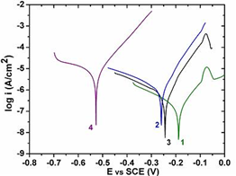 | Figure 9. Polarization curves of Ni-ZrO2 (1), Ni-10Co-ZrO2 (2), Ni-28Co- ZrO2 (3) and Ni-80Co-ZrO2 (4) composites |
|
3.4.3. Electrochemical Impedance Studies
- The impedance plots of Ni-ZrO2 and Ni-Co-ZrO2 composites with various cobalt contents are shown in Figures10 and 11. Figure 10 represents the Nyquist plot. The interception of Z’ in the Nyquist plot at higher frequencies is ascribed as electrolytic bulk resistance Rs and at lower frequencies the interception is ascribed as the charge transfer resistance Rct.
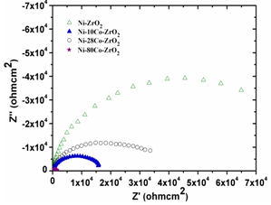 | Figure 10. Nyquist plots of Ni-ZrO2, Ni-10Co-ZrO2, Ni-28Co-ZrO2 and Ni-80Co-ZrO2 composites |
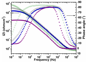 | Figure 11. Bode Plots of Ni-ZrO2, Ni-10Co-ZrO2, Ni-28Co-ZrO2 and Ni-80Co-ZrO2 composites |
|
3.6. Wear Behaviour
- The comparative wear volume loss for plain Ni, Ni-Co alloys and Ni/Ni-Co-ZrO2 composite coatings is listed in Table 6. It is seen from the table that the wear volume loss for the composite coatings is remarkably less compared to that of plain Ni and Ni-Co alloy coatings.
|
4. Conclusions
- The effect of nano ZrO2 incorporation in Ni and Ni-Co matrix was studied by developing Ni-ZrO2 and Ni-Co-ZrO2 composites through electrodeposition method under optimized conditions with respect of microhardness. The FESEM studies showed that the surface morphology of Ni-ZrO2 composites comprised of polyhedral crystallites along with agglomerated ZrO2 particles. However, the surface morphology of Ni-Co-ZrO2 composites depended on the Co content. A change in morphology from polyhedral- nodular-ridged was observed with increase in Co content from 10wt% - 80wt%. A change in crystal structure from fcc to hcp was seen for a similar change in Co content. It was observed from the thermal stability studies that the stability in terms of microhardness was higher for Co rich Ni-80Co- 5ZrO2 composite coating upto temperatures of 800oC compared to Ni-ZrO2 and other Ni rich Ni-Co-ZrO2 composite coatings. The immersion corrosion studies revealed that the corrosion occurred by localized pitting in the case of Ni rich Ni-Co/Ni composites and that the corrosion rate was the least in Ni-28Co-ZrO2 composite coating. Ni-80Co-5ZrO2 composite displayed uniform and higher corrosion rate compared to Ni rich composites. However, the polarization and electrochemical studies showed that the corrosion behaviour of Ni-ZrO2 composite was better than that of Ni-Co composites. However, the behaviour of Ni-28Co-ZrO2 coating is very close to that of Ni-ZrO2 coating. It was seen from the wear studies that Ni-10Co-2ZrO2, Ni-28Co-2ZrO2 composites displayed better wear resistance. Thus, Ni-28Co-2ZrO2 composite appears to be optimum in terms of corrosion and wear resistance. Depending on the functional requirement, Ni-Co-ZrO2 composite coatings can be tailor made to meet different needs.
ACKNOWLEDGEMENTS
- The authors would like to thank the Director, NAL for permission to carry out this study. A special word of thanks to Mr.Siju, Ms.Latha and Mr.Muniprakash for their assistance in performing the FESEM, microhardness and wear analysis. Ms.Kavitha is also acknowledged for her assistance in performing the experiments.
References
| [1] | Robertson, A, Erb, U, Palumbo, G, 1999, “Practical applications for electrodeposited nanocrystalline materials.” Nanostruct. Mater., 12, 1035-1040 |
| [2] | Wang, W, Qian, SQ, Zhou XY, 2010, “Microstructure and Oxidation-resistant of ZrO2/Ni coatings applied by high- speed jet electroplating. ” J. Mater. Sci., 45, 1617-1621 |
| [3] | Gul H, Kihc F, Aslan S, Alp A, Akbulut H, 2009, “Characteristics of electro-co-deposited Ni-Al2O3 nano- particle reinforced metal matrix composite (MMC) coatings.” Wear, 267, 976-990 |
| [4] | Wang S-C, Wei W-C. J,2003, “Kinetics of electroplating process of nano-sized ceramic particle/Ni composite.” Mater. Chem. Phys., 78, 574-580 |
| [5] | Carac G, Benea L, Iticescu C, Lampke T, Steinhauser S, Wielage B, 2004, “Codeposition of cerium oxide with nickel and cobalt : Correlation between microstrucutre and microhardness.” Surf. Eng., 20, 353-359 |
| [6] | Liu Y, Ren L, Yu S, Han Z, 2008, “Influence of current density on nano-Al2O3/Ni+Co bionic gradient composite coatings by electrodeposition.” J. Univ. Sci. Technol., 15, 633-637. |
| [7] | Xiaozhen L, Xin L, Aibing Y, Weijue H, 2009, “Preparation and Tribological performance of electrodeposited Ni-TiB2- Dy2O3 composite coatings.”J. Rare Earth, 27, 480-485 |
| [8] | Simunkova H, Garcia P.P, Wosik J, Angerer P, Kronberger H, Nauer G .E, 2009, “ The fundamentals of nano- and submicro- scaled ceramic particle incorporation into electrodeposited Ni layers : Zeta potential measurements.” Surf. Coat.Technol., 203, 1806-1814 |
| [9] | Balathandan S, Annamalai V.E, Seshadri S.K, 1992, “ Electrocomposite coating of partially stabilized zirconia dispersed in a nickel matrix.”J. Mater. Sci. Lett., 11, 449-451 |
| [10] | Qu N.S, Zhu D, Chan K.C, 2006, “ Fabrication of Ni-CeO2 nanocomposite by Electrodeposition.” Scripta Mater., 54, 1421-1425 |
| [11] | Gomez E, Pane S, Valles E, 2005, “ Electrodeposition of Co-Ni and Co-Ni-Cu systems in sulphate-citrate medium.” Electrochim. Acta, 51, 146-153 |
| [12] | Wang L, Gao Y, Xue Q, Liu H, Xu T, 2005, “Microstructure and Tribological properties of electrodeposited Ni-Co alloy deposits.” Appl. Surf. Sci., 242, 326-332 |
| [13] | Wang W, Guo H.T, Gao J.P, Dong X.H, Qin Q.X, 2000, “XPS, UPS and ESR studies on the interfacial interaction in Ni-ZrO2 composite plating.”J. Mater. Sci., 35, 1495-1499 |
| [14] | Setare E, Raeissi K, Golozar M.A, Fathi M.H, 2009, “The structure and corrosion barrier performance of nanocry- stalline zirconia electrodeposited coating.” Corros. Sci., 51, 1802-1808 |
| [15] | Valov, Stoychev D, Marinova Ts, 2002, “ Study of the kinetics of process during electrochemical deposition of zirconia from nonaqueous electrolytes.” Electrochim. Acta, 47, 4419-4431 |
| [16] | Stoychev D, Ikonomov J, Robinson K, Stefanov P, Stoycheva M, Marinova Ts, 2000, “Surf. Interface Anal., 30, 69-73 |
| [17] | Rajiv E.P, Annamalai V.E, Seshadri S.K, 1992, “Transformation - toughened cobal - partially stabilized zirconia electrocomposite coating,” J. Mater. Sci., 11, 466-468 |
| [18] | Benea L, Lakatos-Varsanyi M, Maurin G, ‘The Annals of Dunarea De Jos’ University of Galati Fascicle IX Metallurgy and Materials Science, ISSN 1453-083X NR.II- 2003,10-17 |
| [19] | Zhang K.F, Ding S, Wang G.F, 2008, “Different superplastic deformation behaviour of nanocrystalline Ni and ZrO2/Ni nanocomposite.” Mater. Lett., 62, 719-722 |
| [20] | Hou F, Wang W, Guo H, 2006, “Effect of the dispersibility of ZrO2 nanoparticles in Ni-ZrO2 electroplated nanocomposite coatings on the mechanical properties of nanocomposite coatings.” Appl. Surf. Sci., 252, 3812-3817 |
| [21] | Wang, Hou F-Y, Wang H , Guo H-T, 2005, “Fabrication and characterization of Ni-ZrO2 composite nano-coatings by pulse electrodeposition.” Scripta Mater., 53, 613-618 |
| [22] | Moller A, Hahn H, 1999, “Synthesis and Characterization of Nanocrystalline Ni/ZrO2 composite coating.” NanoStruct. Mater., 12, 259-262 |
| [23] | Reddy B.S.B, Das K, Datta A.K, Das S, 2008, “Pulsed co-electrodeposition and characterization of Ni-based nanocomposites reinfroced with combustion-synthesized, undoped, tetragonal-ZrO2 particulates.” Nanotech., 19, 15603- 115613 |
| [24] | Ramesh Bapu G.N.K, Jayakrishnan S, 2006, “Oxidation characteristics of electrodeposited nickel-zirconia composites at high temperatures.” Mat. Chem. Phys., 96, 321-325 |
| [25] | Zhang J, Wang D.-Y, Sun Z.-F, Zhao W.-L, Guo X.-Y, “Wuhan Ligong Daxue Xuebao/J.Wuhan Univ. Tech., 2008, 30: 21 |
| [26] | H Klung, L Alexander, “X-ray Diffraction Procedures for Polycrystalline and Amorphous materials”, 618 John Wiley, New York (1974) |
| [27] | Srivastava M, William Grips V.K, Rajam K.S, 2007, “Electrochemical deposition and Tribological behaviour of Ni and Ni-Co metal matrix composites with SiC nano-particles.” Appl. Surf. Sci., 253, 3814-3824 |
| [28] | S.W Banovic, B.F Levin, J.N DuPont, A.R Marder, ‘Progress Report prepared for U S Department of Energy under Grant No. DE-FG22-95PC95211’, Project Period: 7/14/95- 12/31/97 |
| [29] | Srivastava M, William Grips V.K, Rajam K.S, 2009, “Influence of Co on Si3N4 incorporation in electrodeposited Ni.” J. Alloy Compd., 469, 362-365 |
| [30] | Srivastava M, EzhilSelvi V, William Grips V.K, Rajam K.S, 2006, “Corrosion resistance and microstructure of electrodeposited nickel-cobalt alloy coatings.” Surf. Coat. Tech., 201, 3051-3060 |