-
Paper Information
- Next Paper
- Previous Paper
- Paper Submission
-
Journal Information
- About This Journal
- Editorial Board
- Current Issue
- Archive
- Author Guidelines
- Contact Us
American Journal of Materials Science
p-ISSN: 2162-9382 e-ISSN: 2162-8424
2011; 1(1): 5-11
doi: 10.5923/j.materials.20110101.02
Mechanical and Microstructural Analysis of Carbon nanotube Composites Pretreated at Different Temperatures
S. Bal 1, S. S. Samal 2, U. K. Mohanty 2
1Department of Physics, National Institute of Technology, Silchar, 788010, India
2MME Department, National Institute of Technology, Rourkela, 769008, India
Correspondence to: S. Bal , Department of Physics, National Institute of Technology, Silchar, 788010, India.
| Email: |  |
Copyright © 2012 Scientific & Academic Publishing. All Rights Reserved.
Carbon nanotube (CNT) based epoxy composites have been fabricated and were subjected to different temperature conditions. Flexural moduli and hardness of all samples were determined. The resulting composites demonstrated enhanced physical properties due to the addition of high strength CNTs. Effect of temperature on mechanical properties of composites has been examined microscopically by SEM through fracture surface. Results confirmed that nanocomposites pretreated with hot water are found to be tough and those treated in liquid nitrogen are brittle. Uniform distribution of CNTs in the matrix and bridging of crack initiation by CNTs contribute to maintain structural integrity under variable temperature.
Keywords: Carbon Nanotube, Polymer, Nanocomposite, Fracture Surface
Cite this paper: S. Bal , S. S. Samal , U. K. Mohanty , "Mechanical and Microstructural Analysis of Carbon nanotube Composites Pretreated at Different Temperatures", American Journal of Materials Science, Vol. 1 No. 1, 2011, pp. 5-11. doi: 10.5923/j.materials.20110101.02.
Article Outline
1. Introduction
- The discovery of carbon nanotube (CNT) has promoted research in many different areas out of which the most intriguing applications of CNT is the polymer/CNT nanocomposites[1-5]. The high mechanical, electrical and thermal property of CNT makes them ideal candidate as fillers in lightweight polymer composite[6]. Nanotube-reinforced polymer composites have become attractive structural materials not only in the weight-sensitive aerospace industry, but also in the marine, armor, automobile, railway, civil engineering structures, and sporting goods industries because of their high specific strength and specific stiffness. Different nanocomposites have been synthesized by incorporating carbon nanotubes into various polymer matrices, such as polyamides[7], polyimides[8–10], epoxy[11], polyurethane[12–13] and polypropylene[14–16]. Epoxy resin is most often used as the polymer matrix with reinforcing nanotubes for advanced composite applications. The resins of this class have good stiffness, specific strength,dimensional stability and chemical resistance, and show considerable adhesion to the embedded fiber[17]. Because micro-scale fillers have successfully been synthesized with epoxy resin[18–21], nanoparticles, nanotubes, and nanofibers are now being tested as filler material to producehigh performance composite structures with enhanced properties[22–24].For aerospace applications, nanotube reinforced composites must be able to survive in extremely low temperature conditions without any structural degradation. Besides, increase in temperature may catalytically enhance the chemical reaction between the nanotubes and polymer in nanocomposites. Studies on micromechanical properties and fracture surface of nanocomposites pretreated in different conditions have been reported[25], where low hardness and flexural strength obtained in case of CNT/epoxy composites in comparison to pure epoxy samples. The comprehensive understanding of the fracture behaviour and crack propagation in nanocomposites is significant regarding the performance under practical conditions. The enhancement of toughness in composites was demonstrated by modifying polymer with multiwall carbon nanotube (MWNT) that explains nanotube bridging phenomenon[26]. This bridging mechanism of nanotubes reduces the growth of nano-pores as well as the crack propagation in the composite that contributes positively to fracture toughness. The effect of the stiffness of epoxy matrix to the reinforcement role of carbon nanotubes was evaluated by controlling the curing process[27]. So maintaining the structural integrity under variable temperature conditions has become an important issue for CNT based nanocomposites. Keeping in view of the above facts, in the present investigation ductile epoxy/MWNT composite has been fabricated for the first time following refrigeration method. The ductile nanocomposites had shown improved mechanical and electrical properties that is reported in[28]. In this work, the nanocomposites were pretreated under ambient, sub ambient (cryogenic) and intermediate temperatures. Flexural and hardness tests were performed to evaluate mechanical performances of those samples. Microscopic approaches were used to investigate the material’s fracture behavior and filler dispersion mechanisms.
2. Experimental Methods
2.1. Materials
- MWNTs used in this study for the preparation of nanocomposites were obtained from MER corporation, USA. They were produced by arc plasma method (purity 95%, length 1-5 μm and diameters 20-70 nm). SEM morphology of the products (Figure 1) was carried out with a "JEOL JSM-6480 LV Scanning Microscope". Epoxy polymer matrix was prepared by mixing epoxy resin (Ciba-Geigy, araldite LY-556 based on Bisphenol A) and hardener HY-951 (aliphatic primary amine) in wt. ratio 100/12. Epoxy resin (5.3-5.4 equiv/kg) was of low processing viscosity and good overall mechanical properties.
2.2. MWNT/Epoxy Composite Preparation
- In the present work nanocomposites were prepared by taking very low loading of MWNTs (0.2 wt%) in the epoxy resin. The MWNTs were first dispersed in ethanol solution under manual stirring in order to optimise the dispersion. After complete evaporation of ethanol, the obtained MWNT powder was added to the epoxy resin and sonicated for 2 hrs at room temperature. Further, hardener was added to this epoxy/ MWNT mixture and sonicated for 15 min. Then one part of the mixture was allowed to set in room temperature and another part was set under refrigeration condition. Refrigeration facilitates in preparing ductile samples by increasing settling time of the mixture in comparison to room temperature. Pure resin samples without adding carbon nanotubes were also fabricated in the same method as above for comparison purpose. All composite samples along with resin samples were cured for 5 hrs at 80°C in an oven. The prepared samples were cut according to the mechanical test (flexural & hardness) configuration and then treated at different environmental conditions for 24 hrs, these were: (a) room temperature (20 0C), (b) hot water (80 0C) and (c) in the cryofreezer at liquid nitrogen (-180 0C) temperature. The pure resin samples were named as R0 (treated at room temp.), H0 (treated in hot water), C0 (treated in cryofreezer) and the corresponding ductile samples were named as DR0, DH0 and DC0.. Identification of epoxy/ MWNT nanocomposites is done as: R1 (room temp.), H1 (hot water), C1 (cryofreezer). The corresponding ductile nanocomposites samples were designated as DR1, DH1 and DC1.
2.3. Flexural Test
- Five rectangular specimens from each sample were taken for three-point bend test as per ASTM D790 (width=2.7cm, thickness=0.7cm, span=11.2cm, length=12cm) and subjected to different temperature conditions. The flexural test was conducted immediately once the beams were picked up from the specified environments. The tests were carried out at ambient temperature using Instron 1195 keeping the cross-head speed 2 mm/min. Flexural modulus of each sample was determined from the average value of five specimens.
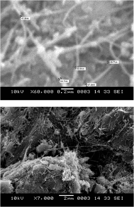 | Figure 1. SEM of Multiwall carbon nanotubes (MWNTs). |
2.4. Hardness of Nanotube Composites
- The hardness of all nanotube composites was measured using a micro-hardness tester. A total of 10 points on each of the nanotube composites were measured in order to get average readings. The unit and magnitude of the hardness are defined by Vickers hardness and determined by measuring the average diagonal length of the indentation. Hardness of each sample was determined from the average value of five specimens.
2.5. Surface Topography Characterization
- Scanning electron microscope (Jeol JSM-6480 LV) was used to conduct the dispersion behaviour and fracture surface topography characterization. After mechanical test fracture surfaces were coated with a thin platinum layer.
3. Results and Discussion
3.1. Flexural Measurements
- Flexural modulus of pure resin & its CNT composite and ductile resin & its nanocomposite samples were found to be R0, 24.52; R1, 136.86; DR0, 44.15; DR1, 176.38 MPa. As shown in Figure 2, increase in flexural modulus was more pronounced in samples treated in hot water (H0, 49; H1, 148.8; DH0, 64; DH1, 210 MPa) in comparison to samples treated in cryofreezer (C0, 33; C1, 140.2; DC0, 36; DC1, 159.3 MPa). All the composite samples i.e. R1, DH1, C1 & DC1 were showing greater modulus than pure resin samples that is attributed to the high mechanical strength of CNT. The results of the ductile/ refrigerated samples were showing variable behaviour. Ductile sample treated in hot water (DH1) showed the modulus to be 210 MPa which is 9 times of resin sample R0. This may be due to the reason that at high temperature the filler can constrain the mobility of polymer chains as well as their relaxation spectra[29], which can change the glass transition temperature[29, 30] and modulus of the matrix. The ductile composite samples after submerged into liquid nitrogen (DC0 and DC1) revealed reduction in flexural modulus in comparison to room temperature treated samples (D0 and D1). The cause of reduction was may be due to contraction of the matrix, which increased the clamping stress to the nanotube surface, and thus increased the frictional force between the nanotubes and the matrix.
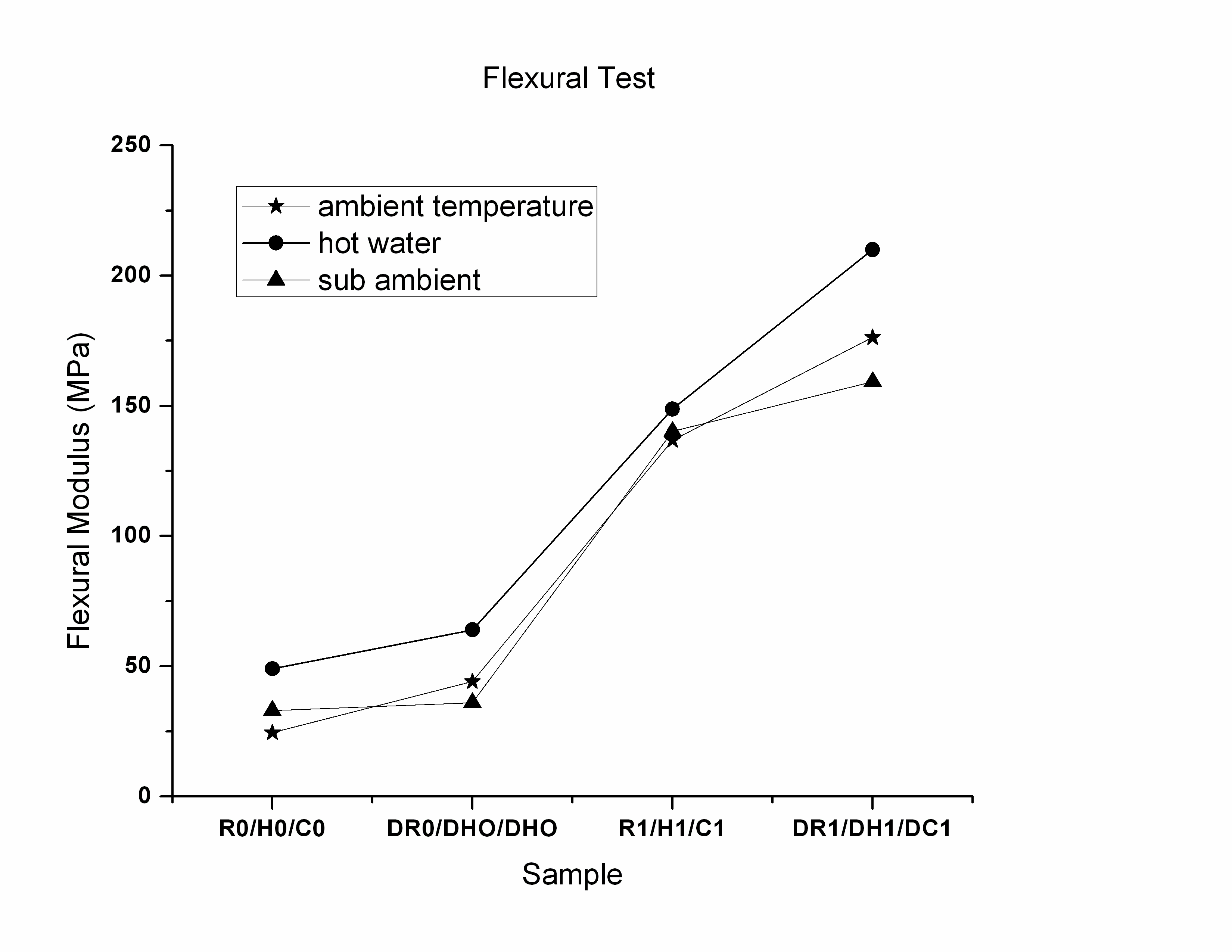 | Figure 2. Flexural moduli of resin as well as composite samples placed in different environment. |
3.2. Hardness of Nanotube Composites
- A considerable enhancement of hardness was observed (Figure 3) by conditioning the nanocomposites in different temperature environments.
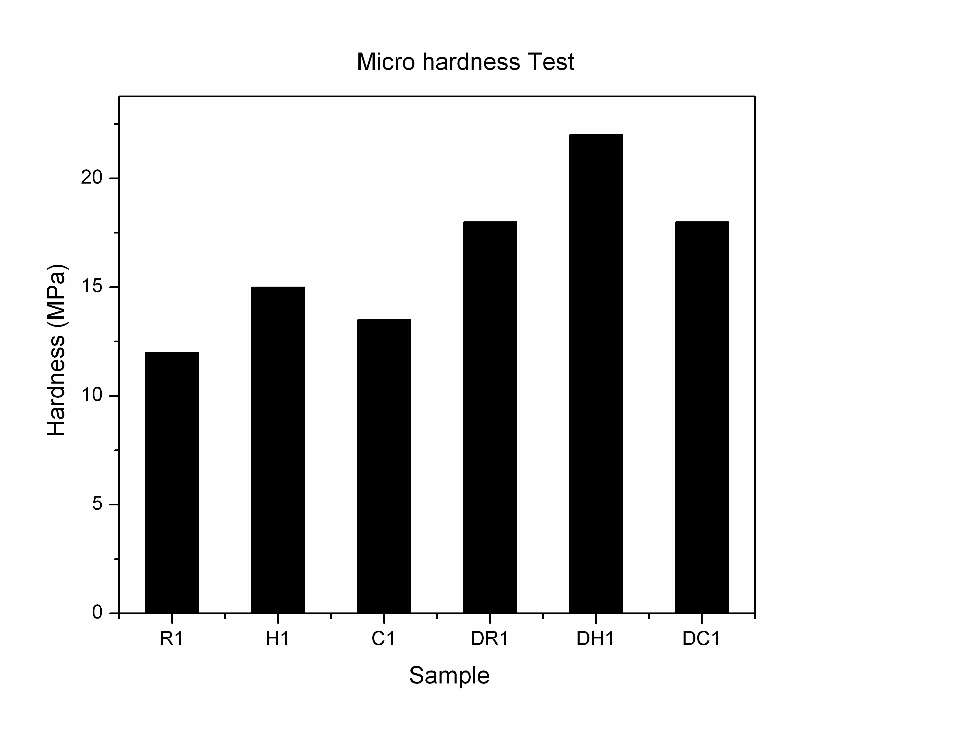 | Figure 3. Hardness of nanotube composites and their ductile ones. |
3.3. Fracture Surface Analysis
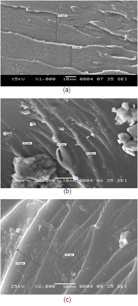
- The investigation of the fractured surfaces to analyse the micro deformation and crack propagation mechanism has been carried out using scanning electron micrograph (SEM).DH1 (Figure 4b) exhibited a relatively smooth fracture surface than DR1 (Figure 4a) while DC1 (Figure 4c) indicated a typical fractography feature of brittle fracture behavior, thus accounting for the low fracture toughness. The distance between two cleavage steps in DR1 (Figure 5a) was about 23-32 µm and the cleavage plane between them was flat and featureless. The fracture surfaces of the nanocomposites DH1 & DC1 show considerably different fractographic features. For example, the failure surfaces of the nanocomposite were rougher with the hot and cold conditioning (Figure 5 b&c). The higher magnification SEM picture showed that the size of the cleavage plane decreased to 14-18 µm in case of DC1 and 6-15 µm in case of DH1. The decreased cleavage plane and the increased surface roughness imply that the path of the crack tip was distorted making crack propagation more difficult.
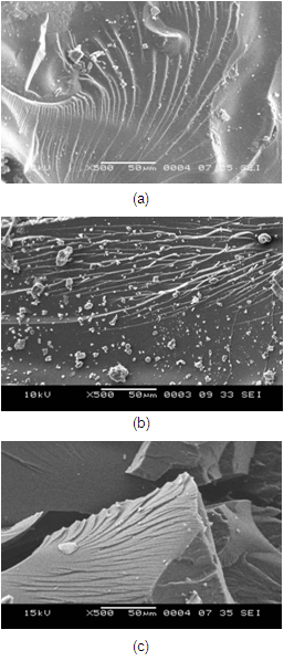 | Figure 4. Fracture surface of ductile composite samples (a) DR1, (b) DH1 and (c) DC1. |
 | Figure 5. Cleavage plane of ductile composite samples (a) DR1 (b) DH1 (c) DC1. |
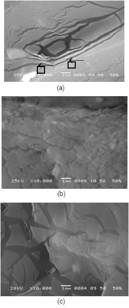 | Figure 6. Crack features of ductile carbon nanotube composites (a) DR1 (b) DH1 (c) DC1. |
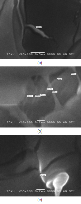 | Figure 7. Crack features in hot water ductile composite sample DH1: (a) carbon nanotube inside a crack (b) bridging of crack by MWCNT (c) extension of a single MWCNT over the crack. |
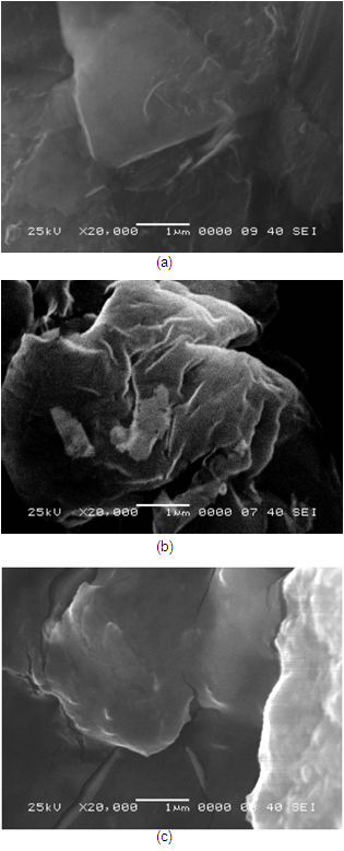 | Figure 8. Distribution of CNTs in ductile carbon nanotube composites (a) DR1 (b) DH1 (c) DC1. |
4. Conclusions
- All the composite samples demonstrated enhanced mechanical properties than pure resin samples that is attributed to addition of high strength nanotubes. Ductile composite samples treated in hot water at 800C showed more improved modulus due to restriction in the mobility of polymer chains. SEM of fracture surface of these samples revealed better dispersion of CNTs in comparison to corresponding room temperature and cryofreezer samples supplementing the mechanical test results. Investigation of tough fracture surface of those materials revealed that narrower crack-tips underneath the advancing cracks were more efficiently bridged by the nanotubes resulting in an increased resistance against crack propagation. Reduction in flexural modulus and hardness value in other nanocomposites was due to formation of agglomerates of nanotubes inside polymer matrix. The fracture surface of the composite material pre-treated in liquid nitrogen was brittle in nature where CNTs were distributed near the crack. So in those cases failure occured quickly due to which flexural modulus decreased. This study demonstrated that the nanocomposites that were prepared by low temperature settlement and then treated in hot water found to be structurally more stable under different temperature conditions.
ACKNOWLEDGEMENTS
- The first author is thankful to Department of Science and Technology, Govt. of India for the financial support to carry out this research.
 Abstract
 Reference
 Full-Text PDF
 Full-Text HTML