John A. Korinthios1, Efstathios Sykas2, Apostolos Xenakis1, Konstantinos Kalovrektis1, Georgios Stamoulis1
1Department of Computer Science and Telecommunications, University of Thessaly, Lamia, Greece
2Electrical and Computer Engineering, National Technical University of Athens, Athens, Greece
Correspondence to: John A. Korinthios, Department of Computer Science and Telecommunications, University of Thessaly, Lamia, Greece.
| Email: |  |
Copyright © 2020 The Author(s). Published by Scientific & Academic Publishing.
This work is licensed under the Creative Commons Attribution International License (CC BY).
http://creativecommons.org/licenses/by/4.0/

Abstract
Signalling load optimization on the air-interface is vital for mobile telecommunications. There is a trade-off between signalling load due to the need to update the mobile location (tracking update load) when in idle mode versus the signalling load to locate the mobile when paged. This paper demonstrates that there is an optimum size for a Tracking Area List (TAL) in terms of Tracking Areas (TAs). The solution is provided in analytical form, and it is applicable to the mobile network technologies that adopt the flexible TAL method for tracking update, which means it is applicable in 4G/LTE Networks and it is targeted for future (5G) mobile networks.
Keywords:
Mobility tracking, Signalling, Mobile Networks, 4G/5G Networks
Cite this paper: John A. Korinthios, Efstathios Sykas, Apostolos Xenakis, Konstantinos Kalovrektis, Georgios Stamoulis, Mobility Tracking Signalling Optimisation in Mobile Networks, Journal of Wireless Networking and Communications, Vol. 10 No. 1, 2020, pp. 17-21. doi: 10.5923/j.jwnc.20201001.03.
1. Introduction
4th Generation (4G) Mobile Networks based on the All-IP paradigm are aggressively deployed worldwide and 5th Generation (5G) mobile networks will emerge in the forthcoming years. In mobile (cellular) networks, the service area of the network is partitioned into non-overlapping areas that can be called registration areas. Location Management (LM) procedure keeps track of the location of user equipment (UE) with the accuracy of the registration area. In the Global System for Mobile Communications (GSM) and the Universal Mobile Telecommunications System (UMTS), the registration area is called Location Area (LA) in the circuit-switched domain and Routing Area (RA) in the packet-switched domain. In the Long-Term Evolution (LTE), a registration area is called a Tracking Area (TA).In GSM and UMTS, the partitioning of the network in LAs/RAs was static. LTE adopted a more dynamic method for mobility tracking. The network allocates to a UE a group of TAs, which is called TA list (TAL). The UE performs Tracking Area Updates (TAUs) when moving into a TA that is not included in the allocated TAL [1]. The allocation of TAL can be performed per UE, which adds to the dynamic nature of the method. The TA can vary from one cell to several cells.In LTE when the UE is in connected mode and has an active session, the mobile network knows the UE position with the accuracy of a cell. When the UE is in idle mode (does not have any active session), the mobile network knows the UE position with the accuracy of a TAL area. Paging has to be performed within this area to reveal the exact position of the UE. Therefore, in LTE, the PA is equal to the TAL area. The optimal design of TAL is a tradeoff between the volume of TAUs and the volume of paging messages. An upper bound of 16 TAs per TAL is defined [5]. There is considerable research effort in the area that has not produced so far an analytical solution to the problem. An extensive literature review in this research area is provided in [1].The aim of this paper is to provide a framework solution for optimizing (minimizing) the signaling load in the air-interface due to mobility management in mobile networks that adopt the TAL concept. This framework can be flexibly adopted to 4G/LTE networks as well as in future mobile networks that will adopt the TAL method. The rest of the paper is organized as follows: In section 1 we give an introduction regarding technical background of LTE systems. Following, in section 2 we argue regarding the optimization framework of future 4G/5G networks, adopting TAL method. In section 3, we present and discuss our analytical results and in section 4 we conclude our paper with discussion.
2. Mobility Tracking Optimization
2.1. Crossing Rate through a Random Curve
Given a random closed curve of perimeter La (m), surface Sa (m2), an average density σUE (m-2) of UEs, an average speed vUE (m/sec) of UEs in the neighbourhood of the curve and assuming random movement of MTs, then the crossing rate λin,a λout,a (sec-1) in both sides of the random curve is [2]: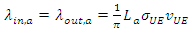 | (1) |
where, the factor  exists due to the random movement of the MTs, an assumption made here for simplicity, that can be substituted given geographical constrains (i.e. streets crossing the curve) [3].
2.2. Estimation of Signalling Load over the Air-Interface
In cellular systems the minimum TA is possibly the cell area. The minTA is denoted with a and it is used to achieve maximum granularity when defining the TAL area. The signalling load λa (bytes/sec) over the air-interface in minTA is given by:  | (2) |
where, λtu,a (messages/s) is the tracking update rate, λh,a is the handover rate, λp,a is the paging rate, λs,a is the session rate, and ltu, lh, lp and ls are the corresponding message lengths (bytes/message).The handover rate is proportional to the rate of MTs that cross into the minTA while having an active session, | (3) |
where A=λ/(λ+μ) is the probability of having an active session, 1/λ is the average time between sessions and 1/μ is the average duration of the session. Assuming that, when a UE crosses the curve while having an active call a handover takes place, which also updates the tracking information without the need for an explicit tracking update, then it holds: | (4) |
where, xa is the fraction of the minTA perimeter, which is also part of the TAL perimeter, therefore 0≤ xα ≤1. • If xa =0, then the minTA is in the middle of the TAL and has zero tracking update rate. • If xa =1, then the complete minTA border is part of the TAL border. The session rate (incoming and outgoing) depends on the number of the MTs in the area and is given by [4]: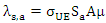 | (5) |
Assuming equal incoming and outgoing session rates, the paging rate is given by: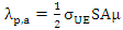 | (6) |
where S is the surface of the complete TAL area, thus  assuming N minTAs within the TAL. The total signalling load λa in a minTA is expressed as:
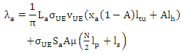 | (7) |
2.3. Minimization of Signalling Load
The goal is to minimize total air-interface load for the complete network. It is sufficient to minimize the load in a minTA. Since the definition of the TAL can be made per UE then in order to minimize the overall signalling traffic in a minTA it is sufficient to minimize the signalling traffic per UE. The traffic per UE λa,i in a minTA can be given by the following equation: | (8) |
In the following sections, we apply various approximations regarding the shaper of the TAL area in order to minimise the signalling load per UE.
2.4. Cyclic Sector Approximation and Analytical Solution
We approximate the randomly shaped TAL area with a circle of radius R and surface S and the randomly shaped minTA with a cyclic sector with surface Sa [4]. Let N the number of minTAs in a TAL, the perimeter La of a circle sector is given by: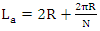 | (9) |
the fraction xa of the minTA perimeter, which is also part of the TAL area perimeter of the circle sector is then given by: 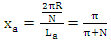 | (10) |
Therefore, the total signalling load over the air-interface is given by: | (11) |
We consider λa,i as a function of N because the rest of the parameters are in fact constant for a given UE. The minimization of the total signalling load λa,i with respect to N is equivalent to: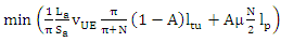 | (12) |
which expresses the trade-off between the tracking update and paging. The minimum can be found by differentiating with respect to N and setting the derivative equal to zero: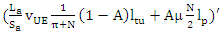 | (13) |
We define the following constants: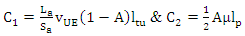 | (14) |
which leads to: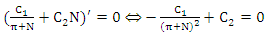 | (15) |
and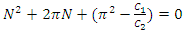 | (16) |
The last equation has two possible solutions, but only the following one is potentially a positive number: | (17) |
By substituting and since N is an integer greater than zero, we obtain: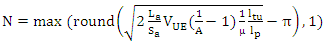 | (18) |
The ratio La/Sa depends on the minTA shape and is minimized in the case the cell shape is a circle (La/Sa =2/Ra). A close to real life approximation can be a cyclic sector with surface 1/3 of the circle then La/Sa =2*(π+3)/(πRa). Therefore, there is an optimal N>0, which in the trivial case, N=1, implies a TAL equal to the minTA/cell.
3. Solution Application and Results
3.1. Normal Hexagon and Square Pattern Approximation
We can approximate the randomly shaped minTA with either a normal hexagon or a square with surface Sa, and in this case we build the TAL area according to the following process depicted in Fig. 1.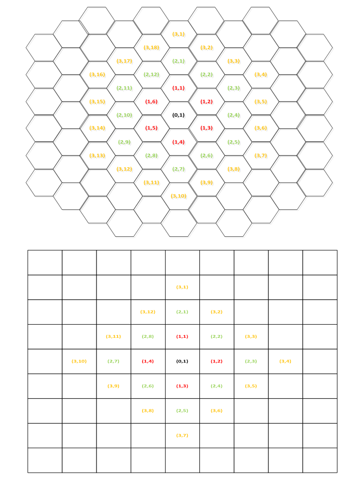 | Figure 1. TAL area based on normal Hexagon or Square minTAs |
The TAL area in both cases are built in the following way: We first start with a central minTA. Then start to add minTAs in a cyclic way, so that each free edge on the central minTA is covered by one additional minTA. In this way, we establish successive rings on minTAs over the central minTA. By building the TAL in this way, we ensure that the perimeter L over surface S ratio is minimized for the TAL. The number Nn of peripheral minTAs in a ring n, where n=0, 1, 2, 3… is given by: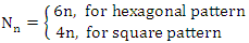 | (19) |
The total number N of minTAs in the TAL is given by: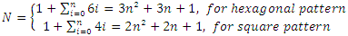 | (20) |
The above equation obviously holds when each ring is completed around the previous one. The infinite set of valid N according to the above is described below: 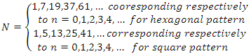 | (21) |
However, in order to achieve flexibility in the formation of the TAL, we will use eq. (20) as an approximation for intermediate N other to those included in the set of eq. (21).The geometrical aspects are therefore calculated: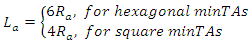 | (22) |
and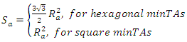 | (23) |
It is obvious that xa is not constant throughout the TAL area because a minTA can be either at the middle of the TAL area or at the border. However, we can calculate XTAL, LTAL and STAL,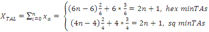 | (24) |
 | (25) |
In order to achieve flexibility in the formation of the TAL area, we are applying the same extrapolation principle introduced above by defining the equivalent (average)  for all minTAs as follows:
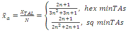 | (26) |
we solve eq. 22 according to n taking the positive solution: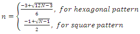 | (27) |
Then, by substituting the solution on eq. (29) and obtain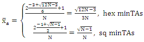 | (28) |
Finally, we substitute in eq. (9) and obtain: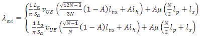 | (29) |
Since λα,i is a function of N, the minimization of the total signalling load λα,i with respect to N is equivalent to: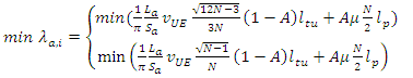 | (30) |
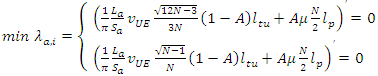 | (31) |
We define the constants: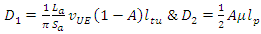 | (32) |
Which leads to the equations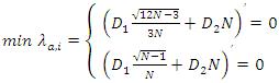 | (33) |
Finally, we obtain: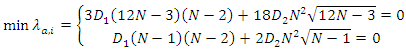 | (34) |
The above equations can be solved using arithmetical methods.
3.2. Numerical Results and Comparison
Typical values for vue are 50 km/h for a vehicle user, 3 km/h for a pedestrian user and 0,1 km/h for an almost stationary user. The probability A for web browsing is approximately 18%, since 1/λ≈1200 sec and 1/μ ≈ 265 sec, respectively, based on empirical data [6]. For video streaming apps the average session duration is approximately 20 min [6], thus A equals to 50%. The message lengths ltu and lp are not fixed due to the optional fields. In 4G/LTE the length of the RRC paging message is normally 90 octets, which is decomposed in 16 S-TMSI (SAE-Temporary Mobile Station Identifier), 5 octets long each, plus the message overhead [7]. Therefore, lp=90/16=5,625 bytes. In the literature [8], [10], ltu is considered 5 to 10 times larger than lp. In LTE [9] the tracking update procedure requires the 3 NAS messages (Tracking Area Update Request /Accept /Complete), 3 RRC messages (RRC Setup /Accept /Complete) and the two Random Access Preamble /Response messages. Therefore, an ltu/lp ratio of 15 is more appropriate for the 4G/LTE context.In Fig. 2 the optimum number N of cells is illustrated versus the cell radius, for various typical values for the involved parameters. The optimum N decreases as the cell radius increases. The higher the user mobility Vue and the lower the probability A of having an active session or the session duration 1/μ the higher becomes the optimum Ν.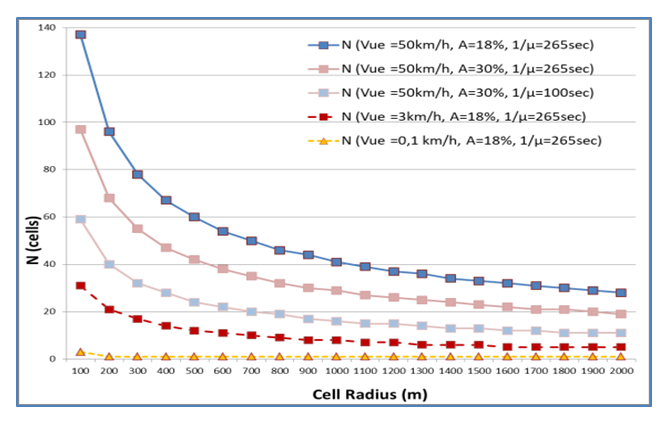 | Figure 2. Optimum number N of cells in a TAL versus radius (Cyclic Sector) |
In Fig. 3 the combined signalling load per user of the tracking update & paging messages is depicted as a function of the number N of cells in a TAL taking the case of pedestrian users as an example. The signalling load as a function of number N of cells in a TAL initially decreases rapidly as N increases and the minimum is rather flat, not sensitive to varying values of Ν, in a rather wide range near the min.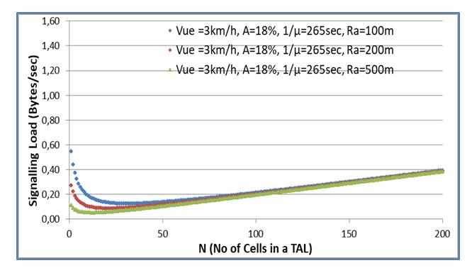 | Figure 3. Signalling load / user versus No of cells in a TAL (Cyclic Sector) |
Taking the same assumptions as in the cyclic sector pattern, in Fig. 4 and Fig. 5 the combined signalling load per user of the tracking update & paging messages is depicted for the cases of the Hexagon and Square minTAs. By comparing the results depicted in Fig. 3, Fig. 4 and Fig. 5, we can observe that the results are very similar, which proves the validity of the approach under various assumptions of the minTA pattern. Especially the results from cyclic sector and Square minTAs are very similar in absolute terms. Most important, the minimum appears for same N in all three cases.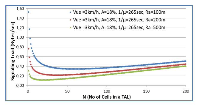 | Figure 4. Signalling load / user versus No of cells in a TAL (Hexagon) |
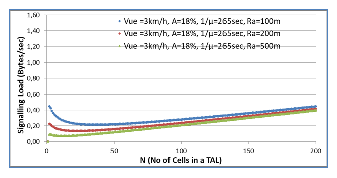 | Figure 5. Signalling load / user versus No of cells in a TAL (Square) |
4. Conclusions
We have proven that for each UE there is an optimum number N of neighbouring minTAs/cells to include in the TAL, so that the signalling load over the air-interface is minimised. An analytical solution to the tracking update versus paging message signalling load trade-off has been provided. The total signalling traffic is minimized per UE, consequently per minTA and as a result in the complete network. Optimised results were obtained if each minTA is considered as a cell. This approach provides maximum flexibility. Cells of approximately the same size are considered, which is a reasonable assumption for specific geo areas at macro level. Small cells are expected to share the TA of their corresponding macro cell. The proposed framework calculates the optimum number N of neighboring cells that constitute the TAL per UE, which utilises the flexibility available in LTE networks and is applicable for future networks (5G). The optimum number N of neighboring cells is determined by a number of parameters including the cell perimeter La (m), the cell surface Sa (m2), average speed of the UE vue (m/sec), A the probability of having an active session and 1/μ the average session duration. All these parameters can be calculated or approximated every time a tracking update takes place. Therefore, the number N will not only be optimised between UEs but can be optimised for the same UE within the day, in case different behaviour during the day is depicted.The analytical solution has been developed assuming a cyclic sector pattern. Two additional patterns (normal hexagon and square) have also been examined and results have been found to be analogous. We would like to emphasize that the proposed optimization is flexible because: a) it can be applied individually for each UE b) it is based on parameters that can be evaluated in real time and c) the optimal size can be updated regularly based on the changing user habits.
References
| [1] | S. M. Metev and V. P. Veiko, Laser Assisted Microtechnology, 2nd ed., R. M. Osgood, Jr., Ed. Berlin, Germany: Springer-Verlag, 1998. |
| [2] | J. Breckling, Ed., The Analysis of Directional Time Series: Applications to Wind Speed and Direction, ser. Lecture Notes in Statistics. Berlin, Germany: Springer, 1989, vol. 61. |
| [3] | S. Zhang, C. Zhu, J. K. O. Sin, and P. K. T. Mok, “A novel ultrathin elevated channel low-temperature poly-Si TFT,” IEEE Electron Device Lett., vol. 20, pp. 569–571, Nov. 1999. |
| [4] | M. Wegmuller, J. P. von der Weid, P. Oberson, and N. Gisin, “High resolution fiber distributed measurements with coherent OFDR,” in Proc. ECOC’00, 2000, paper 11.3.4, p. 109. |
| [5] | R. E. Sorace, V. S. Reinhardt, and S. A. Vaughn, “High-speed digital-to-RF converter,” U.S. Patent 5 668 842, Sept. 16, 1997. |
| [6] | M. Shell. (2002) IEEEtran homepage on CTAN. [Online]. Available: http://www.ctan.org/tex-archive/macros/latex/contrib/supported/IEEEtran/. |
| [7] | FLEXChip Signal Processor (MC68175/D), Motorola, 1996. |
| [8] | “PDCA12-70 data sheet,” Opto Speed SA, Mezzovico, Switzerland. |
| [9] | A. Karnik, “Performance of TCP congestion control with rate feedback: TCP/ABR and rate adaptive TCP/IP,” M. Eng. thesis, Indian Institute of Science, Bangalore, India, Jan. 1999. |
| [10] | J. Padhye, V. Firoiu, and D. Towsley, “A stochastic model of TCP Reno congestion avoidance and control,” Univ. of Massachusetts, Amherst, MA, CMPSCI Tech. Rep. 99-02, 1999. |

 Abstract
 Reference
 Full-Text PDF
 Full-text HTML