Jonathan Pinifolo1, Suvendi Rimer1, Babu Paul1, Chisomo Daka2, Chomora Mikeka3, Stanley Mlatho3
1Department of Electrical and Electronic Engineering Science, University of Johannesburg, Johannesburg, South Africa
2Department of Applied Studies, Physics Section, Malawi University of Science and Technology, Thyolo, Limbe, Malawi
3Department Physics, University of Malawi, Chancellor College, Zomba, Malawi
Correspondence to: Jonathan Pinifolo, Department of Electrical and Electronic Engineering Science, University of Johannesburg, Johannesburg, South Africa.
| Email: |  |
Copyright © 2017 Scientific & Academic Publishing. All Rights Reserved.
This work is licensed under the Creative Commons Attribution International License (CC BY).
http://creativecommons.org/licenses/by/4.0/

Abstract
Television White Space is gaining attention as a possible means to help address essential factors associated with ubiquitous availability and adoption of broadband internet. This paper presents a novel enhanced-Gain low Cost Television White Space (TVWS) Z antenna for broadband internet access. The antenna performance is demonstrated in the UHF band. Design of a low cost Television White space Z antenna for the client was previously done and it was deducted that it is possible to assess the spectrum usage using low cost equipment. In this paper, the design aspects and measured results of an enhanced-gain low cost Television White Space Z antenna using a thick diameter copper are presented. ANSYS HFSS software was used and this is the Industry standard tool for simulating 3-D, full-wave electromagnetic fields. In this paper, the gain of the antenna has improved by 4.993dB and the bandwidth has increased from 13MHz to 60MHz as a result of using the thick diameter copper wire with much more lengthened sides and axis.
Keywords:
Antenna, Geometry, Gain, TVWS, HFSS, UHF, MoM
Cite this paper: Jonathan Pinifolo, Suvendi Rimer, Babu Paul, Chisomo Daka, Chomora Mikeka, Stanley Mlatho, Enhanced-Gain Low Cost Television White Space Z Antenna Using a Thick Diameter Copper Wire, Journal of Wireless Networking and Communications, Vol. 7 No. 1, 2017, pp. 21-30. doi: 10.5923/j.jwnc.20170701.03.
1. Introduction
As a result of Federal Communications Commission’s approval of unlicensed use of TV white spaces, the issue of how to use these white spaces has led to innovative technologies such as cognitive radios and a variety of spectrum policy proposals. Cognitive Radio technology [1] is an emerging communication paradigm that efficiently exploits radio spectrum resources, facilitating installation and commissioning of future sophisticated wireless networks. Research has demonstrated that Cognitive Radio networks are composed of communication nodes, based on interactions with the surrounding spectral environment. They are capable of sensing a wide radio spectrum range, dynamically identify locally unused or unexploited frequencies and efficiently access them [2]. There has been a great deal of interest from both academia and the communications industry regarding the use of UHF TV band (470-790 MHz in Europe by so called White Space Devices (WSDs) [3].TVWS is considered to be a low cost solution for providing rural internet connectivity in African communities because of its good radio propagation characteristics hence a requirement to ensure that most equipment is affordable. The paper on design of low cost TVWS Z antenna was recently published in 2015 [4] and this antenna was typically designed as a client antenna for reception of Radio Frequency (RF) signals. See figure 1(a) for the actual fabricated Z antenna sticked to the cardboard paper.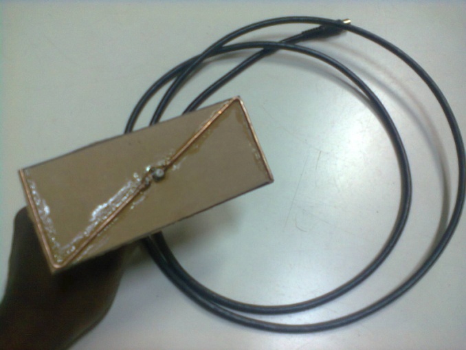 | Figure 1(a). Fabricated TVWS Z Antenna in Physics Lab, Chancellor College, Malawi |
This paper will focus on gain enhancement of the TVWS Z antenna using a thick diameter copper wire and this antenna has been an appropriate choice for broadband internet access because of its improved gain.In respect of paper structure, the rest of the paper is organized as follows: Section 2 presents methodology. Design aspects of the TVWS Z antenna are outlined in section 3 while section 4 presents realization and simulation results. Conclusions have been finally drawn in section 5.
2. Methodology
2.1. Theoretical Background
The Antenna has been designed using a copper wire and it is important to note that Method of Moments (MoM) has emerged to be one of the popular techniques in as far as design of wire antennas is concerned. Generally, a simple formula which is usually used for wire antenna design is pocklington’s integral equation shown in equation (1). 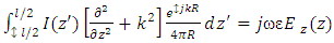 | (1) |
From the above equation, it can be noted that 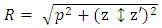 | (2) |
The variables of the above equation are highlighted below:R = Distance linking current source and field observation pointsρ = Wire radiusI (z′) = Current distribution wave equation differential operator (Kernel)
 Free space Green’s functionk=Free space wave number (Constant)Ez(z)=Electric fieldIt is of great importance to note that the electric field denoted as Ez(z) is generated by the current flowing in the wire and the current distribution denoted as I (z′) is stipulated in the span of the wire itself commencing z′ = l/2 up to z′ = –l/2. MoM is quite useful in resolving integral problems and the whole process starts with outlining anonymous current distribution in respect of orthogonal set of basis functions. This paper is focusing on Sub-domain basis functions whereby the copper wire has been demarcated into sections and the current distribution in each section has been modeled by a triangular geometric shape.Expansion function coefficients are portrayed by the amplitudes of these triangular shapes and the constructs intersect as a technique of sustaining current distribution in the wire. Integral equation can now therefore be condensed as outlined below
 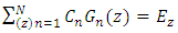 | (3) |
From the above equation, it can be noted that 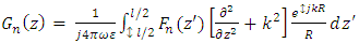 | (4) |
Cn= current’s expansion coefficientFn (z′) = basis functionThe integral equation will further be highlighted as shown below due to the testing function process | (5) |
From the above equation, it can be noted that < > = Inner product operator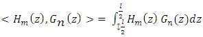 | (6) |
Hm(z) = testing functionThe key aspect to note is that the testing function has got a non-zero value applicable for a particular section of wire situated at 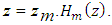 It should further be noted that the point matching is one of the methodologies formulating orthogonal set of testing functions and it is outlined in respect of Dirac delta functions as shown in the equation below.
 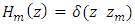 | (7) |
From the above equation, it can be noted that Zm = exact points on the wireBoundary conditions are typically prescribed at zm and the whole boundary condition is imposed by employing all testing functions. Integral equations will eventually be expressed as outlined below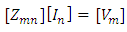 | (8) |
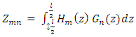 | (9) |
 | (10) |
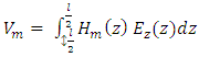 | (11) |
The series of simultaneous linear equations will bring out the value of Cn [5]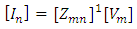 | (12) |
2.2. Important Formulas and Their Applications
Eigenfunction Expansion MethodMost problems pertaining to electromagnetic field have got restrictions towards analytical methods as such numerical methods become more convenient for one to employ when solving such problems. Some of the most common numerical methods include: Eigen function expansion method, Laplace and Fourier transforms, Series expansion, Perturbation methods and Conformal Mapping.The Eigenfunction expansion method is sometimes useful in the derivation of partial Green’s function involving partial differential equations with well-known homogeneous solution [7].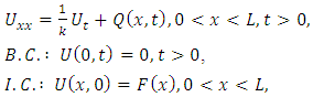 | (13) |
Where the functions  and
and  are defined as:
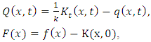 | (14) |
and we use the method of separation of variables to assume the following solution of the partial differential equation [8].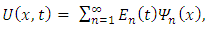 | (15) |
with  being the eigenfunctions fitting to the associated eigenvalue problem
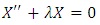 | (16) |
where  represents the time-dependent coefficients. Thus we have:
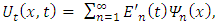 | (17) |
and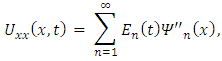 which when combined with (16) results to
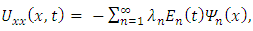 | (18) |
Thus we have 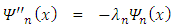 from (19). Rewriting the above equation gives us
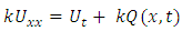 | (19) |
substituting (17) and (18) into (19), we obtain | (20) |
Hence the Fourier coefficients are defined as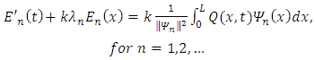 | (21) |
where 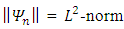 of
of  related as
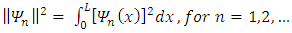 | (22) |
Equation (20) has the following solution | (23) |
for  note that
  are constants. And,
  is defined as
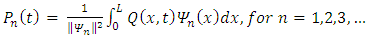 | (24) |
When we substitute (23) into (15) we get | (25) |
3. Antenna Design
3.1. Antenna Geometry
Geometry and Space Orientation (θ, Φ)This paper demonstrates a simple design of an antenna whose geometric outlook is Z-shaped. The antenna has been designed as an improved version on the recent work done [4]. The antenna assumes a horizontal orientation in 3D space with theta (θ) ranging from 0° to 180° and phi (Φ) from 0° to 360° in spherical coordinate systems along the yz axis. This is as shown in figure 2 (a) & (b) below: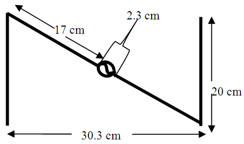 | Figure 2(a). Geometry of the optimized Z-Shaped antenna and its dimensions |
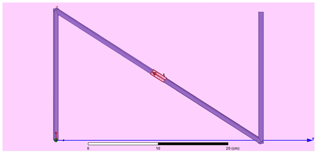 | Figure 2(b). Orientation of the optimized Z-Shaped TVWS antenna along the ZY axis in spherical coordinate system |
3.2. Antenna Specifications
Dimensions and MaterialsIdeally the Z-shaped antenna, shown in figure 2, has been designed and fabricated from copper wire as its physical material with a wire radius of 4mm (i.e. 8mm in diameter). The antenna has a width of 20cm, a length of 30.3cm and an axis of 36.3cm. As seen from figure 2 (a), it is clear that current dimensions of the antenna (including its thickness) are much larger as compared to the previous dimensions on the work done [4]. This change in the dimensions of the designed antenna has also led to a change in the far field characteristics and the general parameters of the antenna (e.g. the gain and bandwidth have been greatly changed) as evidenced by the simulation results.
4. Results and Discussion
The proposed antenna was basically analyzed and optimized with the help of the ANSYS HFSS version 13 antenna simulation tool. The simulation results of interest were plot and discussed below.
4.1. Return Loss [S(1,1)] in dB
The minimum return loss of the designed TVWS Z-shaped antenna was found to be -19.7dB at a resonance or center frequency of 537MHz. From the graph shown in figure 3 (a), the optimum bandwidth of performance for the designed Z-shaped antenna was found to be from 510MHz to 570MHz translating to 60MHz bandwidth. The obtained value demonstrates a greater improvement in bandwidth as compared to the initial 13MHz. The S(1,1) plot in both 2D and 3D are shown in figure 3(a) and 3(b) respectively.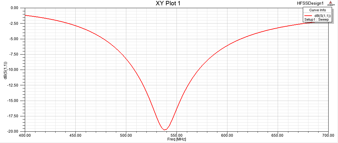 | Figure 3(a). 2D rectangular plot of the return loss in dB |
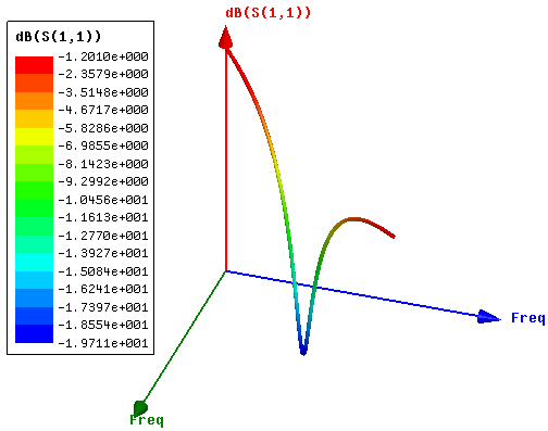 | Figure 3(b). 3D rectangular plot of the return loss in dB |
4.2. Radiation Patterns
The radiation pattern of the designed TVWS Z-shaped antenna was also examined at a single frequency of 550MHz for all the angles theta (θ) from 0° to 360°. From the plots in figures 4(a), (b) and (c), the TVWS Z-shaped antenna is described by an omnidirectional pattern in the combination of the E-plane and M-plane together with observable wide band radiation patterns. Consider the plot in figure below.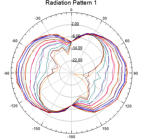 | Figure 4(a). 2D rectangular plot of the radiation pattern |
 | Figure 4(b). Smith chart representation of the radiation pattern |
 | Figure 4(c). 3D polar plot of the radiation pattern |
4.3. Voltage Standing Wave Ratio (VSWR)
The Voltage Standing Wave Ratio (VSWR) is used to describe the performance of the antenna when connected to transmission line. In essence it relates to how well the antenna’s impedance is matched to the transmission line. The ideal value of VSWR is unity (i.e. 1) which indicates that there is no standing wave ratio on the transmission line. For the designed TVWS Z-shaped antenna, the value of the VSWR at a resonating frequency of 537MHz was found to be 1.23, and at some frequency of interest, 550MHz, was found to be 1.36. Both of these values are within the acceptable limits in the designing of antennas. The plots of the VSWR are shown in figures 5(a) and 5(b).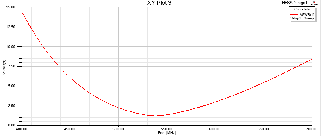 | Figure 5(a). 2D rectangular plot of VSWR |
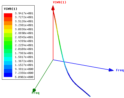 | Figure 5(b). 3D rectangular plot of VSWR |
4.4. Impedance
Impedance stands out to be one of the critical aspects of antenna designing. This is in respect of the fact that for an antenna to perform optimally, the impedance of the antenna itself must be correctly matched to that of the transmission line to which it is connected to. In this regard, the impedance of the antenna ought to be real and within the error bounds of the targeted impedance of the transmission line at the resonating frequency [12]. The designed TVWS Z-shaped antenna had an impedance of exactly 50Ω at all the frequency ranges (including the center frequency of 537MHz). Figure 6 shows 3D plot of the impedance.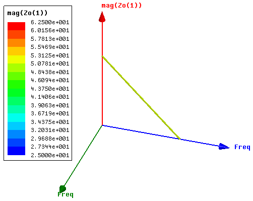 | Figure 6. 3D rectangular plot of magnitude of impedance Z0 (in ohms) of the optimized Z-shaped antenna |
4.5. Gain
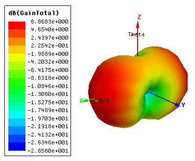
The Gain of the antenna refers to the ratio of the radiation intensity in a given direction to the radiation intensity that would be obtained if the antenna radiates all of the power in all the directions [13]. For the optimized Z-shaped antenna, the peak gain was found to be 6.868 dB as shown in figures 7(a) and (b). This value demonstrates a quite gigantic improvement as compared to the un-optimized antenna which had a peak gain of 1.875dB, which gives a gain difference of 4.993dB.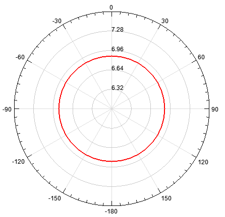 | Figure 7(a). 2D rectangular plot of gain in dB |
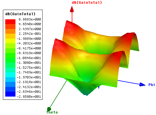 | Figure 7(b). 3D rectangular plot of gain in dB |
4.6. Radiated Power (dBm)
The average radiated power of the antenna was found to be 29.63dBm with a voltage source of 1Volt. This is shown below in figures 8.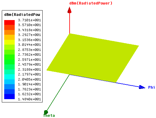 | Figure 8. 3D rectangular plot of radiated power in dBm |
4.7. Radiation Efficiency
In general terms efficiency refers to the ratio of the output to the input in any given system. In particular, the radiation efficiency refers to the ratio of the power radiated by the antenna to the power in the transmission line. For the optimized Z-shaped antenna, the average efficiency of the antenna at the resonant frequency of 537MHz was found to be 93.9% while at 550MHz it was found to be 93.4%. The plots in figure 9(a) and (b) show the average efficiency of the optimized Z-shaped antenna at frequencies 537MHz and 550MHz and theta (θ) from 0° - 360°.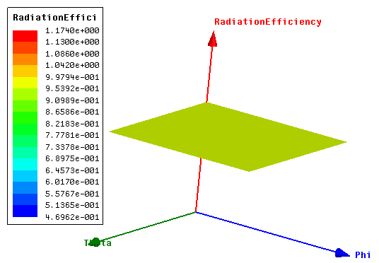 | Figure 9(a). 3D rectangular plot of radiation efficiency of the optimized Z-shaped antenna at 537MMHz |
 | Figure 9(b). 2D rectangular plot of radiation efficiency of the optimized Z-shaped antenna at 550MMHz |
5. Conclusions
In this paper, a simulation-based optimization method for the design of an antenna has been presented. For this optimized TVWS Z-shaped antenna, the peak gain was found to be 6.868 dB. The antenna gain has demonstrated a huge improvement as compared to the initial unoptimized antenna which had a peak gain of 1.875 dB. In essence, the gain of the antenna has been improved by 4.993 dB. Additionally, simulation results have also indicated that the bandwidth has tremendously increased from 13 MHz to 60 MHz. TV White Spaces can help to improve Internet access across Africa and other developing regions. This can be achieved by reducing internet costs in the sense that Internet Service Providers who are able to make innovative use of spectrum can assist to create more competition in markets for Internet access.
ACKNOWLEDGEMENTS
This work is based on the research supported in part by the National Research Foundation of South Africa for the Grant No. 93990. The Authors would like to strongly support the ongoing work by CSIR-Meraka and University of Malawi in collaboration with Malawi Communications Regulatory Authority in making TVWS a success story in Africa.
References
| [1] | Akyildiz. I.F., Lee. W. Y., Vuran., M.C., and Mohanty. S., 2006 “Next generation/dynamic spectrum access/cognitive radio wirless networks: a survey” Computer Networks, vol 50, no13, 2006. |
| [2] | Mastorakis. G., Mavromoustakis. C. X., Bourdena. A., and Pallis. E., 2013 “An Enegry-Efficient Routing Scheme using Backward Traffic Difference Estimation in Cognitive Radio Networks” In proceedings of IEEE. |
| [3] | Wyglinski. A.M., Nekovee. M., and Hou. T., 2010 “Cognitive radio communications and networks: principles and practice” Academic Press. |
| [4] | Pinifolo. J. et al., 2015 “Design of a low cost Televison White Space Z Antenna” In proceedings of IST-Africa 2015 Conference. University of Johannesburg, South Africa. |
| [5] | Rawle. W.D and Aerospace. S., 2006 “The Method of Moments: A numerical Technique for Wire Antenna design”2006 High Frequency Electronics. |
| [6] | Voogt. J., “Introduction to Antenna Types and their application” Engineering Electromagnetics. |
| [7] | Monsefi. F., 2015 “Mathematical Tools Applied in Computational Electromagnetics for a Biomedical application and antenna analysis”. Malardalen University Press Dissertations. |
| [8] | G. Sparr. “Kontinuerliga System”, Lund Institute of Technology, Department of Mathematics, Sweden. Lund 1984. |
| [9] | D. Colton, R. Kress. “Inverse Acoustic and Electromagnetic Scattering Theory”, 2nd Edn. Springer-Verlog Berlin Heidelberg New york, 1998. |
| [10] | K. Atkinson, W. Han. “Theoretical Numerical Analysis”, A Functional Analysis Framework. Springer-Verlog, New York, Inc., 2001. |
| [11] | G. Kristensson. “Spridningsteori med tillampningar”, Studentlitteratur, Lund, Sweden, 1999. |
| [12] | Vashist. S. et al., “Generic Approach in Antenna Design”, International Journal of Emerging Science and Engineering (IJESE), Vol.1, No. 9, ISSN: 2319 -6378, pp. 70 – 75, July 2013. |
| [13] | Alam. H., “Design Rectangular Microstrip Patch Antenna for IEEE 802.15.3a (WPAN) with MB-OFDM Ultra Wide Band Communication Systems”, International Journal of Scientific and Research Publications (IJSRP), Vol.4, No.2, ISSN: 2250-3153, February 2014. |

 Abstract
 Reference
 Full-Text PDF
 Full-text HTML