Olabode B. Idowu-Bismark, Augustus E. Ibhaze, A. A. Atayero
Electrical & Information Engineering Dept Covenant University, Ota, Nigeria
Correspondence to: Olabode B. Idowu-Bismark, Electrical & Information Engineering Dept Covenant University, Ota, Nigeria.
| Email: |  |
Copyright © 2017 Scientific & Academic Publishing. All Rights Reserved.
This work is licensed under the Creative Commons Attribution International License (CC BY).
http://creativecommons.org/licenses/by/4.0/

Abstract
The world is going digital by the day and the need for digital data communication such as high definition video streaming, web browsing and machine to machine communication due to internet of things (IoT) are on the increase continually, such applications require high data rate to deliver them and without increase in bandwidth which is an expensive resource constant. Also in order for 3G cellular system operators to compete favorably in the mobile data market with new competing technologies such as WIMAX, LTE etc especially in the future explosive IoT market and to preserve their investment a cost effective way is to utilize the Multiple Input and Multiple Output antenna system otherwise called MIMO to obtain the needed high data rates. In this paper we looked at the various data rate optimization techniques of MIMO and their applications in 3G networks. Using a drive test we conducted investigation and compare the impact of MIMO on the throughput of legacy Rel. 99, HSDPA and HSPA+ Rel. 9. The result of our investigation shows that while Rel. 99 offered a 0.403Mbps in the uplink, HSUPA offered 1.335Mbps with HSPA+ showing a throughput of 10.950Mbps. Likewise throughput in the downlink is 0.244Mbps, 1.041Mbps and 35.370Mbps for Rel. 99, HSDPA and HSPA+ respectively showing a progressive increase as the number of transmit antenna increases at the base station.
Keywords:
Diversity, HSPA+, MIMO, Spatial Multiplexing
Cite this paper: Olabode B. Idowu-Bismark, Augustus E. Ibhaze, A. A. Atayero, Mimo Optimization Techniques and Their Application in Maximizing Throughput for 3GPP HSPA+, Journal of Wireless Networking and Communications, Vol. 7 No. 1, 2017, pp. 1-8. doi: 10.5923/j.jwnc.20170701.01.
1. Introduction
It is pertinent that since 3G cellular systems cannot be done away with and must compete in the mobile data industry with the new technologies that has inherent capacity for higher data rate, we must look for a solution to high data rate demand that uses the 3G cellular infrastructure [1]. One of such solutions is the improvement of performance and spectral efficiency using MIMO. MIMO takes advantage of the space dimension to enhance network capacity, increase range and improve reliability. MIMO does all these without additional bandwidth nor increased transmit power. The application of higher order modulation and MIMO in 3G cellular systems like the HSDPA produces the Evolved HSPA+. High data rate demand, high network capacity and coverage are the basic challenges of every wireless cellular networks as users demand for data usage soars, various technologies, methods and optimization techniques have been designed for network improvement and spectral efficiency. One way is to maximize 3G network performance through MIMO optimization techniques, thereby enabling it to offer higher data rate, better quality of service and quality of end user experience. In section 2 of this paper, we looked at the MIMO system and its various optimization techniques. We considered MIMO evolution in 3GPP HSPA/HSPA+ in section 3, while the result of our drive test were presented in section 4. We concluded in section 5.
2. MIMO System
2.1. MIMO Basic Models
There are four basic antenna configuration models which include Single Input Single Output (SISO) where the transmitter and receiver of the radio system have only one antenna each, next is the Single Input Multiple Output (SIMO) where the receiver has multiple antennas but the transmitter has only one antenna followed by Multiple Input Single Output (MISO), here the transmitter has multiple antennas and the receiver has only one antenna. Finally Multiple Input Multiple Output (MIMO) which means that both the transmitter and receiver have multiple antennas. This is as shown below in Fig 1.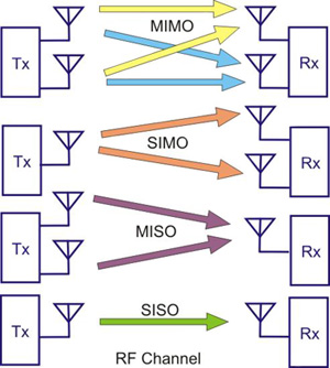 | Figure 1. Different Antenna Format |
2.2. Channel Capacity for MIMO
For the purpose of simplicity, MIMO channel capacity can be represented by the approximated formula below. 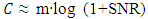 | (1) |
Where m is the number of antennas in either the transmitter or receiver, whichever one is smaller. From the equation, we could see that MIMO system offers spectral efficiency that increases linearly with the increase in the number of antennas, where multiple parallel channels were created to deliver more data traffic streams simultaneously. Figure 2 below shows SISO, SIMO, MISO, and MIMO systems for 2-antenna and 4-antenna spectral efficiency comparison cases. It is observed that significant spectral efficiency improvement can be achieved using MIMO system. [2]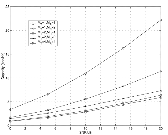 | Figure 2. Spectral efficiency comparison graph. [3] |
2.3. MIMO Channel Model
In MIMO systems, the transmitter sends multiple streams of signals by multiple transmit antennas. The transmit streams of signals go through a matrix channel which consists of all N transmit and N received paths between the Nt transmitting antennas and Nr receiving antennas. The receiving multiple antennas on getting the received signal vectors decodes them into the original information. A narrowband flat fading MIMO system is thus modeled with Equation (2) below. The variables are matrices of complex numbers rather than scalar numbers. | (2) |
Where r and s are the received and transmit vectors, while H and n are the channel matrix and the noise vector respectively as shown in Figure 3 below. [11] | Figure 3. MIMO Matrix |
The channel state information is represented by H, the channel matrix where each of its entries is a distortion coefficient acting on the transmitted signal phase and amplitude in time-domain. The H matrix is constructed by the receiver, the transmitter does not have an idea of what the channel looks like, this state is called open loop system where the transmitter is transmitting blindly. In the event that there is a path for the receiver to transmits this matrix information to the transmitter, the transmitter would then be able to see the status of the signals at the receiver and might make adjustments in the powers allocated to its antennas based on this information, this is called closed loop system [4].The entire process above can be called channel estimation. Channel estimation is a very important part of MIMO performance enhancement. Through channel estimation, we are able to measure time delays, attenuation, and phase (as a function of frequency) of each path between transmit and receive antennas in order to maximize our signal recovery and hence performance.
2.4. MIMO Optimization
The aim of MIMO Optimization is the achievement of the highest possible throughput and connectivity within the network and within a given environment by taking advantage of the multipath potentials of that environment.
2.4.1. Hindrance to MIMO Optimization
All interference limited networks such as the 3G cellular systems including HSDPA and HSPA+ have a major hindrance in the application of MIMO to optimize and increase throughput [5]. Under interference limited networks, all users transmit on the same frequency, therefore internal interference generated by the system is the most important factor that limits the system capacity and determines call quality. For maximum capacity to be achieved, the signal to noise ratio (SNR) of all users must be at the minimum level required for acceptable channel performance. Interference decreases the SNR of the network and reduces system capacity and throughput, [5]. Interference in cellular systems includes self–cell interference, other–cell interference and co–antenna interference [5]. Thus the major hindrance to the application of MIMO in CDMA 3G cellular networks is interference management.
2.5. Types of MIMO Techniques
2.5.1. Spatial Multiplexing
Spatial multiplexing using M transmitting and N receiving antennas allows the capacity of a MIMO network system grows linearly with the minimum of M or N without the use of extra bandwidth or transmit power. MIMO works as a combination of SIMO and MISO otherwise called receive diversity and transmit diversity respectively (where signals from different paths were combined together to form a stronger single signal with higher SNR), resulting in even greater SNR gain than either of them, it does this by sharing the total SNR between its multiple data streams with each of them having a lower power level. The result is that each data stream will have a lower SNR than would be possible if it were a single data stream. As each data stream recombines multipath signals to increase its SNR, diminishing returns sets-in and each data stream is limited or capped by the value of the original data stream SNR. Therefore, each of the multiple data stream may be capable of convening nearly as much data as a single original stream. [14].This spatial multiplexing technique is very important in a high SNR situation where the system is degree-of-freedom limited rather than power limited. Quoting Foschini G.J, Zheng. L et al (2003) stated that the capacity of a channel with M transmit and N receive antennas with independent and identical distributed Rayleigh faded gains between each antenna pair is given byC (SNR) = min {M, N} log SNR + δFrom the above, it is shown that the degree of freedom is the minimum of M and N and the channel capacity increases linearly with M and N. Figure 4 below shows the block diagram of a spatial multiplexing technique.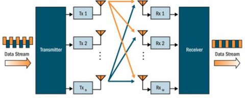 | Figure 4. Spatial Multiplexing |
2.5.2. Spatial Diversity
Diversity is the ability to use different ''channels'' to convey the same information stream from the transmit antenna to the receive antenna when the different channels fade in a statistically independent fashion in such a way that the information may be retrieved from the channel or channels with the best signal to noise ratio (SNR).There are two types of spatial diversity:1. Transmit diversity: where more than one transmit antenna is used to send coded information to one receive antenna.2. Receive diversity: where one transmit antenna send coded information to more than one receive antennas.We lay more emphasis on transmit diversity as a result of its wide spread application in 3G cellular network.2.5.2.1. Transmit Diversity Due to the surge for data usage and multimedia services particularly in the downlink, improving the downlink capacity has thus become one of the challenges facing the evolution of the 3G technology. Transmit diversity (TD) is therefore one of the contributing technology of MIMO for addressing this problem in 3G WCDMA and CDMA2000. while TD provide diversity gain, channel state feedback can be incorporated to provide antenna gain in which case we will have either Open loop TD (without feedback) or Closed loop TD (with feedback). [6] One of the worst types of channel conditions are slow changing flat fading channels as this type of channel condition can result in the received signal been below the background noise level thereby making communication unreliable.Transmit diversity can enhance the performance of the receiver in the face of flat fading. TD reduces the effect of fading by offering multiple independent copies of the signal at the receiver where the probability of all copies of the signals been in a fade simultaneously is very small. [7]. Transmit diversity is achieved by employing large antenna spacing of the order of several carrier wavelength between the transmit antennas leading to uncorrelated fading of the transmit signals. TD has the advantage that the multiple antennas and the complex coding are implemented at the transmitter (Base station) which has enough space and complexity to accommodate them rather than at the receiver (Mobile station), TD is thus used at the downlink of 3G WCDMA systems [8].
2.5.3. Space Time Codes
Space Time Coding is a method of coding that brings together various techniques for obtaining spatial multiplexing gains and diversity gains for a communication link. There are several techniques grouped under space time coding which are used to achieve spatial multiplexing and diversity gains. Space time code can be divided or classified into two. Space Time Block Code (STBC) and Space Time Trellis Code (STTC). An application of the STBC is in space time transmit diversity (STTD). This STTD is used in UMTS 3G cellular systems mandatorily for the mobile station but not compulsory for the base station, the improved signal to noise ratio provided by STTD is used by the mobile station for cell edge performance [9]. STTC on the other hand works by combining modulation and trellis coding to transmit information over multiple transmits antennas and MIMO channels.
2.5.4. Spatial Multiplexing Vs Spatial Diversity
Comparatively SM outperform SD where high signal scattering environment exist and the SNR is relatively high like near the base station whereas when the SNR is weak, like at cell edge, SD outperforms SM because SD will improve the SNR and help offer increased data rate [5] thus an ideal wireless cellular system will incorporate both SM and SD with the system calculating the optimal crossover point between the two in such a way that the system dynamically switches between the two to offer the necessary coverage (offered by SD) or capacity gain (offered by SM) depending on channel condition. [10]
3. MIMO Evolution in 3GPP HSPA+ Release 7 to 9
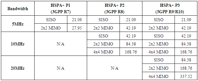
The 3GPP UMTS/WCDMA standard started with Rel.99 in 1999 and run through Rel.4, Rel.5, Rel.6 and Rel.7. Rel.8 upward is actually considered as LTE, as the evolution path of UMTS/WCDMA is towards LTE. The cellular network system is divided into two parts; the radio network part and the core network part. Comparatively, the Rel.99 and Rel.4 core network did not differ much from each other [11]. As we move from Rel.4 to Rel.5, there was a tremendous change both in the core network and in the UTRAN where IP multimedia subsystem was introduced in the core network while IP transmission technology and the High Speed Data Packet Access (HSDPA) technology were introduced in the UTRAN. Rel.5 thus brought with it the introduction of smart antenna in the UTRAN. Although not a full fledge MIMO system, it has a great impact on the throughput. The MIMO technology was actually introduced in Rel.7.Comparing how the various Releases were able to enhance throughput with the use of MIMO technology, we show below in table 1 and 2 the expected data rates for different releases of HSPA+ in both downlink and uplink respectively in relation to the rank of MIMO and multiple carrier frequency used. Table 1. Expected downlink peak data rate. [11]
 |
| |
|
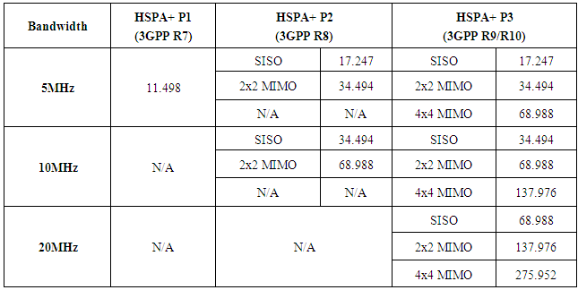
Table 2. Expected uplink peak data rate. [11]
 |
| |
|
Rel.8 came out with further enhancement for HSPA+ such as a dual carrier operation in the downlink and simultaneous operation of MIMO and 64QAM modulation which push the data rate to 42.2Mbps in the downlink while latency was further improved upon. In Rel.9, dual carrier operation was combined with MIMO capabilities to push downlink data rate to 84.4Mbps while the dual cell HSUPA feature supports two carrier frequencies in the uplink leading to 23Mbps data rate. The latest Rel.10 specification uses four carriers HSDPA that enables a single user access to four carrier frequencies of 5MHz each leading to 20MHz bandwidth which is what is available with LTE and WiMAX. [12]
4. Result and Analysis
Having completed our drive test experiment, we proceeded here to analyze the reports obtained. Two experiments were carried out, one for 3G WCDMA/HSDPA and one for 3.75G HSPA+.
4.1. WCDMA Rel.99 and HSDPA Rel.5 Single Cell Functional Test Report
4.1.1. DL Throughput Analysis
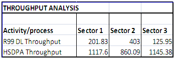
From the result of our experimental test, we see that R.99 sector 1 downlink throughput is low at 201.83Kbps, however this can be explained from the fair (yellow) values of the cell RSSI (Received Signal Strength Indicator) and the SIR (Signal to Interference Ratio) radio parameters, telling us that the channel condition is not too good. Looking closely, we also see that the neighboring cells (U07081, U07082 and U07083) have strong RSCP (Received Signal Code Power) radio parameter values (Green) which is good for handover as they took over most of the traffic, thus negatively affecting our R.99 sector 1 DL throughput.The same applies to the HSDPA sector 1 throughput at not too good value of 1,117Kbps. However, looking at HSDPA sector 2, the SNR value is really bad (Red) at 15.20 which gives the sector throughput value at 880.09Kbps showing and proofing to us that signal to noise ratio is a major factor (enhances or hindrance) to the effect of MIMO in improving throughput and data rate. The above direct throughput measurement results tally with our observed indications from section 4.4 and 4.5 above that our throughput values will be in the fair region/range due to channel conditions as revealed by the collected RF parameters (FTP RSCP and Tx Pwr). Table 3. HSDPA and Rel.99 DL Throughput comparison table
 |
| |
|
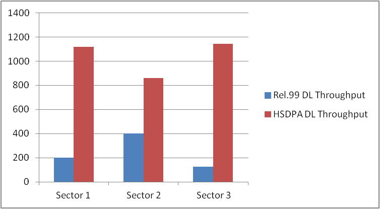 | Figure 5. HSDPA and Rel.99 DL Throughput Comparison chart |
Tabulating the downlink throughput measured for the three sectors of R.99 and HSDPA, we obtain the comparison table (Table 3) and graph (Figure 5) above. The graph revealed a drastic improvement of HSDPA downlink throughput over that of R.99 with an average of over 400% justifying the inclusion of DTxAA antenna system in HSDPA for throughput improvement as compared to the use of TxAA in R.99.
4.1.2. UL Throughput Analysis
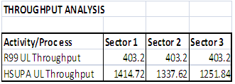
Table 4. HSUPA and Rel.99 UL Throughput Comparison table
 |
| |
|
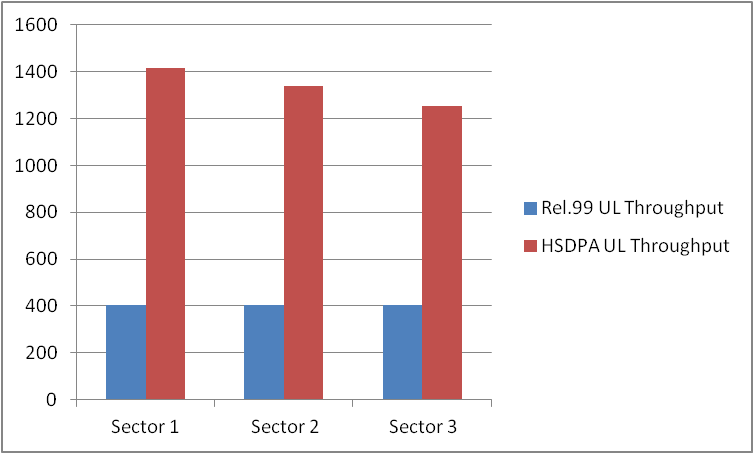 | Figure 6. HSUPA and Rel.99 UL Throughput Comparison Chart |
In the Uplink sector, section 4.1.3 above, tabulating the throughput measured for the three sectors of R.99 and HSUPA, we obtain the comparison table (Table 4) and graph (Figure 6) above showing a HSUPA higher throughput values of about 300% over R.99 UL throughput which is in agreement with the theoretical throughput analysis of HSUPA and R.99 UL.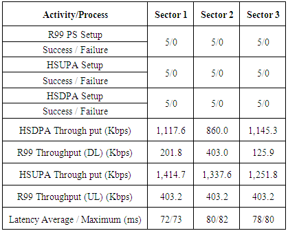
4.2. Throughput and Capacity Test Analysis for HSPA+
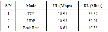
The HSPA+ Rel.9 drive test experiment for throughput measurement was carried out for a 20MHz 4 transmit and 4 receive (4T4R) antenna system for both throughput and capacity test as well as for coverage test to determine the throughput at the cell edge of the network where spatial diversity is used (and not spatial multiplexing that offers higher throughput values).The HSPA+ throughput and capacity test experiment, gave us an uplink throughput in UDP (User Datagram protocol) and TCP (Transmission Control Protocol) of 10.95Mbps and 10.95Mbps respectively while the corresponding values in the downlink are 30.91Mbps and 35.37Mbps respectively.Looking at the outdoor coverage RF parameter of the our result with various measurement values to justify the above high throughput values, we see that the RSRP has values for each sector of the network as -85.5, -83.75 and -98.67 indicating near eNodeB and mid cell location where MIMO uses spatial multiplexing as against spatial diversity for cell edge.Also, at near cell site (near eNodeB), the SINR is usually high which is used by MIMO spatial multiplexing to produce high throughput. Thus the reflected high values of the measured DL SINR at 24, 21 and 22 (all above the parameter high range value of 20 for excellent performance) is justified. Finally, the above high SINR is collaborated by high MCS values (between 17 to 44 corresponding to a modulation order of 6bits/symbol for 64QAM in the MCS index vs. modulation order table) for higher order modulation scheme.The combination of high SINR and high MCS values is expected to give us a high throughput value for the network which is reflected in the measured throughput values for both UL and DL. Putting our result in a tabular form, we have: Table 5. HSPA+ Throughput table analysis
 |
| |
|
The above table shows an average value for the TCP and UDP UL/DL values with a channel peak rate for the UL and DL at 18.63Mbps and 40.35Mbps respectively.
4.2.1. Coverage Test
The coverage test was performed to determine the throughput across the entire network, particularly to determine the throughput values at the cell edge thereby determining the limit of the network before handover takes place.
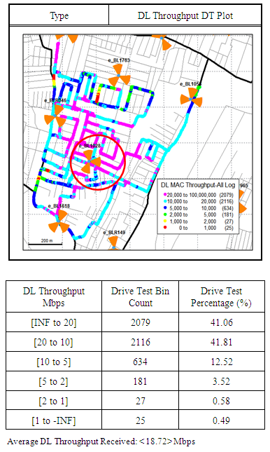
4.2.2. DL Throughput Plot
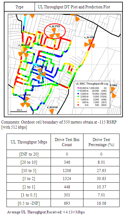
4.2.3. UL Throughput Plot
4.2.4. Coverage Test Analysis
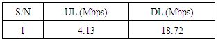
The DL throughput measurement at the cell edge were taken and the result tabulated in section 4.2.2 above with an average DL throughput received value of 18.72Mbps. The same measurement was taken for the UL throughput and the result tabulated in section 4.2.3 with a throughput value of 4.13Mbps. According to section 2.5.4 (Spatial Multiplexing Vs Spatial Diversity), we explained the use of SD at cell edges where SNR is usually low. Thus in such situation as we have now, SD in the form of MISO (Transmit Diversity) is used rather than full MIMO. For our 4T4R antenna system therefore, we have a 4T by 1R MISO system at the cell edge of our network yielding a 18.72Mbps DL and 4.13Mbps UL throughput.Table 6. Cell edge throughput using MISO
 |
| |
|
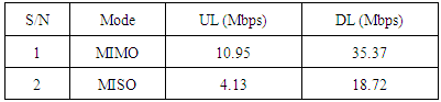
Drawing a comparison table for MIMO and MISO mode for our test experiment result as shown below in table 7, we see and is able to proof that MIMO offers a higher throughput over transmit diversity.Table 7. MIMO and MISO UL/DL throughput comparison table
 |
| |
|
From table 7 above we see MIMO offering about 200% improvement over MISO, however we should note that MIMO would have performed woefully at the cell edge if applied rather than applying MISO thus the use of MISO offers improvement of throughput at the cell edge (when SNR/SINR is lower than what MIMO can cope with).
4.2.5. Final Comparison Analysis
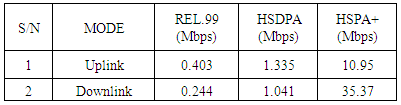
In this paper, we have performed a test experiment to determine the throughput of legacy 3G Rel.99, HSDPA and HSPA+ and in order to verify the impact of MIMO on the performance of HSPA+ over HSDPA and 3G Rel.99, using the average values of the sector throughputs (average of sector 1, 2 and 3 throughput) for Rel.99 and HSDPA we tabulated the result of the measured throughput for each system so as to draw a comparison for our conclusion.Table 8. Rel.99, HSDPA and HSPA+ Throughput Comparison Table
 |
| |
|
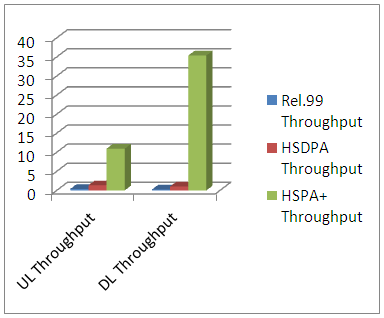 | Figure 7. Rel.99, HSDPA and HSPA+ Throughput Comparison Chart |
From the above table and chart, we are able to compare and see an improvement of the performance of HSPA+ throughput over both HSDPA and legacy 3G Rel.99.Though the DL throughput of HSDPA is lower than its HSUPA UL throughput due to channel conditions, nevertheless the UL/DL throughput values for HSUPA/HSDPA are still far more superior than the values obtained from Rel.99 thus supporting and proofing the effect of DTxAA on HSDPA throughput performance over that of Rel.99 that uses TxAA antenna arrangement. The overriding factors for the above improvement of HSPA+ throughput performance over that of HSDPA and legacy 3G Rel.99 are the multiple bandwidth carrier and the 4x4 MIMO implementation as the HSPA+ (Rel.9) operate a 20MHz bandwidth thus multiplying HSDPA/Rel.99 5MHz bandwidth by a factor of four which is suppose to translate to a throughput improvement factor of four. Also while Rel.99 uses a TxAA antenna arrangement, the HSDPA uses a DTxAA which is twice that of Rel.99 but the HSPA+ uses a 4x4 antenna arrangement, offering and showing us a quantum leap in the amount of throughput available to the end-user as displayed in the above chart.
5. Conclusions
There are different techniques used for drive testing including - Network Benchmarking, Optimization & Troubleshooting, as well as Service Quality Monitoring. The result produced by each drive testing technique differs based on the intended objectives. While Optimization and Troubleshooting technique is more usually used for finding specific problems during the rollout phases of new networks or to monitor specific problems reported by consumers, the Service Quality Monitoring technique normally involves making test calls across the network to a fixed test unit to assess the relative quality of various services using Mean opinion score (MOS). We focus our attention on the Network Benchmarking technique where state of the art multi-channel tools are used to measure several network technologies such as modulation, MIMO and service types simultaneously to very high accuracy [15]. This technique helps to provide comparable information regarding competitive strengths and weaknesses of the network. Result from this technique, such as comparative data network speed analysis and data throughput analysis, are useful in commercial campaigns. Network Benchmarking technique is the only way mobile network operators can collect accurate competitive data on the true level of their own and their competitors technical performance and quality levels. From the result and analysis of our experiment, it is clear that MIMO is efficacious in the provision of improved throughput as we move from legacy 3G Rel.99 through HSDPA to HSPA+ either across different frequency bandwidth or within the same frequency bandwidth.Also, each of its optimization technique such as spatial multiplexing and spatial diversity are effective in providing increased data rate/throughput in their own right based on the channel condition ideal for their operation as we see in the increased throughput provided by spatial diversity at the cell edge where spatial multiplexing would not have been ideal due to bad channel condition (low SINR). Our experimental test shows that though the above hold true, however the practical throughput achieved are far less from the theoretical calculated figures due to channel conditions.
References
| [1] | Spatial Multiplexing in Cellular MIMO- CDMA Systems with Linear Receivers: Outage Probability and Capacity by Wan Choi and Jeffrey G. Andrews, 2008. |
| [2] | MIMO: From Theory to Reality by Ruifeng Wang, 2009. |
| [3] | Multiple Input Multiple Output (MIMO) Systems: Basic Principles, Algorithms and Networking Applications by Harish Ganapathy, 2005. |
| [4] | Tutorial 27- Finding MIMO by Charan Langton, Bernard Sklar, 2011. |
| [5] | Overcoming interference in spatial multiplexing MIMO cellular networks by Jeffrey G. Andrews, Wan Choi, and Robert W. Heath Jr. IEEE Communication magazine Oct 20, 2006. |
| [6] | Overview of Diversity Techniques in Wireless Communication Systems by Hafeth Hourani, 2005. |
| [7] | Transmit Diversity in 3G CDMA Systems by R. Thomas Derryberry, Steven D. Gray, D. Mihai Lonescu, Giridhar Mandyam and Balaji Raghothaman. IEEE Communications Magazine, 2002. |
| [8] | Smart Antenna Implementation for MIMO by Suraya Mubeen, A.M Prasad, A. Jhansi Rani. 2012. Journal of Information Engineering and Application Vol. 2, No 4. |
| [9] | Tutorial: Multiple Input and Multiple Output (MIMO) System Analysis by Jian-Jiun Ding, 2007. |
| [10] | From Theory to Practice: An overview of MIMO space-time coded wireless system IEEE Journal on sel. Areas in communications, Vol. 21 No 3, pp 281-302 by D. Gesbert, M. Shafi, D.Shiu, P.J Smith and A. Naguib April 2003. |
| [11] | HSPA+ Technology by ZTE Corporation, 2012. |
| [12] | HSPA+ Technology Introduction, Application Note by Meik Kottkamp, 2009. A Publication of Rohde & Schwarz. |
| [13] | MIMO- Future Wireless Communication by Pravin W. Raut, Badjate S.L April, 2013. |
| [14] | Maximizing LTE Performance Through MIMO Optimization by PCTEL April, 2011. |
| [15] | Richa Budhiraja1, Jitendra Singh Jadon ''Study And Implementation of Drive Test for Development of GSM Network'' International Journal of Engineering Trends and Technology (IJETT) – Volume 4 Issue 10 - Oct 2013. |

 Abstract
 Reference
 Full-Text PDF
 Full-text HTML