Jawad Rehman, Waseem Shahzad
National University of Computer and Emerging Sciences, Islamabad, Pakistan
Correspondence to: Waseem Shahzad, National University of Computer and Emerging Sciences, Islamabad, Pakistan.
| Email: |  |
Copyright © 2016 Scientific & Academic Publishing. All Rights Reserved.
This work is licensed under the Creative Commons Attribution International License (CC BY).
http://creativecommons.org/licenses/by/4.0/

Abstract
Radio access technology is in a stage of innovation, and LTE (Long Term Evaluation) is one of them. LTE (Long Term Evaluation) delivers higher data rates, greater capacity, and wider coverage. It can work with existing network technologies such as GSM (Global System for Mobile), CDMA (Code Division Multiple Access) and WCDMA (Wideband Code Division Multiple Access). The radio resource management is important component of LTE (Long Term Evaluation) technologies. In E-UTRAN (Evolved-Universal Terrestrial Radio Access Network) radio interface, RRC (Radio Resource Control) belongs to access stratum because it is at the bottom of UN interface. In this paper, first, we describe the introduction of connection establishment procedure in all generations of wireless networks from 0th generation to 4th generation. We thoroughly investigate the layered architecture of LTE (Long Tem Evaluation), architecture of RRC (Radio Resource Control) and role of connection establishment in the entity, Connection establishment procedure at UE (User Equipment) side using SDL diagrams like State diagrams and MSC (Message Sequence Chats), Standard messages format exchanged during connection establishment procedure, Connection establishment procedure at network side using SDL (Sequence Diagram) diagrams like state diagrams and MSC (Message sequence charts), Connection establishment procedure in femtocells using SDL (Sequence Diagrams) Diagrams like MSC (Message Sequence Charts) and its algorithm using access and overlay relation table. In the end, we will provide some future directions.
Keywords:
Wireless networks,Long-Term evaluation, Global system for mobile, Radio resource control, Message sequence charts
Cite this paper: Jawad Rehman, Waseem Shahzad, Critical Analysis of Connection Establishment Procedure in Layer 3 of LTE (Long Term Evaluation), Journal of Wireless Networking and Communications, Vol. 6 No. 3, 2016, pp. 73-84. doi: 10.5923/j.jwnc.20160603.03.
1. Introduction
Wireless technology started in 1970. There are five generations of technologies namely from Zero generation to the fourth generation. The concept of cellular was used in first generation network technology through which today large scale wireless network are possible. In second generation networks, analog technology is replaced by digital technology with improved wireless communication quality. In third generation technologies, the main focus was on data and voice. In fourth generation technology, there are many application opportunities and technological challenges.In zero generation technology, we use technologies like PPT (Push to Talk), MTS (Mobile Telephone System), IMTS (Improved Mobile Telephone Service) and AMTS (Advance Mobile Telephone System). In PPT (Push to Talk), only one connection is established at a time; the user can talk to multiple users and listen by either holding or releasing a button on the device. The user first enters the number of the person and then presses the button to establish a connection. The tower identifies the connection and then connects it through the network to the intended user. The intended user is notified by their phone. If they answer, a connection is established [1] [2].In the first generation, the technologies used are AMPS (Advanced Mobile Phone Service), TACS (Total Access Communication System), NMT (Nordic Mobile Telephone), NAMPS (Narrow Band AMPS), MCS (Mobile Cellular System) and CNET [1]. In the first generation, when a mobile is powered ON, it searched for a set of control channels and selected the strongest one, after it enters into an idle state and waits for an incoming call. When a call is initiated or received, mobile then entered into access mode and connect to the network via control channel then via access channel from the network it receives designation message showing to open voice channel and entered conversation mode. On receiving calls, mobile is notified via paging. Paging message contains MIN (Mobile Identification Number) or telephone no of the phone. On receiving the paging message then the customer is alerted to the incoming call. On receiving a call, mobile send service requests to the network for answer the call. This message contains telephone no and electronic serial no for user identity. In this stage, only voice or customer information is communicated and also control information is exchanged between mobile and network during the call to adjust mobile power level and frequency changes [2].In second generation, we use technologies like GSM (Global System for Mobile), TDMA (Time division multiple access), E-TDMA (Enhanced – TDMA), CDMA (Code division multiple access), GPRS (General Radio Packet Service) and EDGE (Enhanced Data Rate for GSM Evolution) [1]. In the second generation when the mobile phone is switched ON, it starts searching for a set of control channels and then select the strongest one. After initialization, it can receive a paging message through the control channel. In the digital system, it has more control channel then analog system. When a call is received or initiated, mobile enter into system access mode. During this stage, it selects the network and the network send digital traffic channel designation message. The mobile phone then tunes to the designated communication channel and entered into conversion mode and then conversation beings. In this stage, only voice data or another customer data is sent between the network and mobile [2]. In third and fourth generations, the technologies used are WCDMA (Wideband Code Division Multiple Access), CDMA2000 (Code Division Multiple Access), OFDM (Orthogonal Frequency Division Multiplexing), HSDPA (High-Speed Downlink Packet Access) and HUSPA (High Speed Uplink Packet Access) [1]. In these generations, when mobile is switched ON it scan the control channel and measure the signal strength and select the channel with highest signal strength and tunes to BCCH (Broadcast common control channel). On this channel, it can receive paging and system information. Once mobile is camped on a cell with selected PLMN (Public land mobile network), then mobile can initiate a call or receive a call via paging [2].The rest of the paper is organized as follows. Section 2 provides a brief overview of protocol architecture of LTE. Section 3 provides detail of radio resource control entity Section 4 deals with connection establishment procedure at UE side. Establishment procedure at network side is elaborated in section 5. Section 6 reports connection establishment procedure of femtocell network. Conclusion and future directions are given in the last section.
2. Protocol Architecture
The following figure 1 shows the layered view of the protocol stack of LTE (Long Term Evolution). The components involved are UE (User Equipment), eNodeB (Evolved Node B) and MME (Mobile Management Entity).The RRC (Radio Resource Entity) us the third layer of LTE (Long Term Evaluation) and RRC is the main layer of the stack. It contains the connection establishment procedure.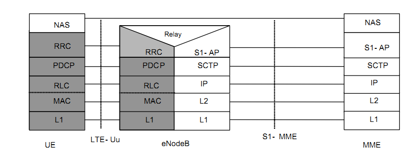 | Figure 1. User Plane of LTE stack [3] |
3. Radio Recourse Control Entity
The RRC entity is a part of LTE (Long Term Evaluation) protocol stack. It can handle allocation of radio resources of the UE and signaling between UE (User Equipment) and eNodeB (Evolved Node B). The following figure 2 shows the RRC component of LTE.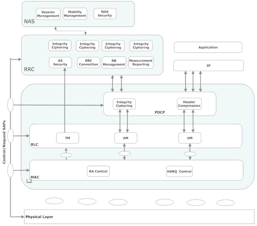 | Figure 2. RRC (Radio Resource Control) Protocol Stack UE Side |
The RRC layer on UE side includes the following components;Ÿ Cell Selection Ÿ System Information AcquisitionŸ PagingŸ Connected Mode MobilityŸ AS(Access Stratum) SecurityŸ RRC Connection Establishment and ReleaseŸ RB(Radio Barrier) ManagementŸ Measurement ReportingFurthermore; RRC layer includes MBMS (Multimedia Broadcast Multicast Service), QoS (Quality of Service) control function, etc. The summary of RRC as; adjusting system resources, maximizing efficiency, avoiding network congestion, holding a load of signals as little as possible and guarantee QoS for network users [4] [5].The following figure 3 shows the RRC (Radio Resource Control) layer on eNodeB (Evolved Node B) side;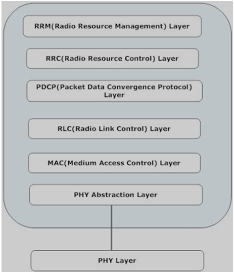 | Figure 3. RRC Protocol Stack eNodeB side |
On eNodeB side, RRC contains the following components;Ÿ System InformationŸ Measurement and Cell selectionŸ HandoverŸ Security and integrityRRC (Radio Resource Control) layer is divided into two states i.e. Idle and connected state. The following figure 4 shows the RRC state diagram [4].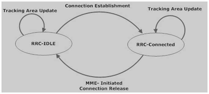 | Figure 4. RRC State Diagram [4] |
In the idle state, RRC monitors the paging channel for incoming calls, system information collection and change, ETWS (Earthquake and Tsunami Warning Service) notification. In the idle state, it can also perform cell measurements and cell selection and re-selection [4] [5] [6].In the connected state, RRC monitors paging channel for incoming calls, System information collection and change, ETWS (Earthquake and Tsunami Warning Service) warning notification, cell measurements, measurement reporting, and handover.
4. Connection Establishment Procedure at UE Side
UE (User Equipment) can make the transition from idle mode to the connected mode using RRC (Radio Resource Control) connection establishment. In the connected state, UE can only transfer any application data. UE and network both can initiate the RRC connection establishment procedure. UE can start connection establishment procedure if the user starts the application for internet or email. The procedure is also started if the UE moves into new tracking area. The network can also initiate the connection establishment procedure by sending a paging message. The paging message is used for delivery of incoming SMS (Short Messaging Service) or incoming voice call [5] [7]. The MSC (Message Sequence Chart) diagram of connection establishment from UE side is shown below in figure 5.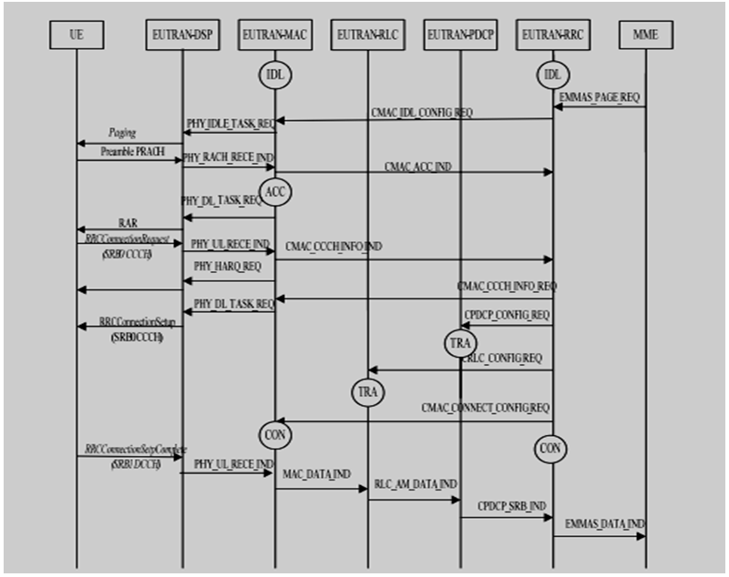 | Figure 5. MSC of connection establishment Procedure [7] |
When RRC get the paging message from the network, it encodes the paging message. Paging message contains S-TMSI (S- Temporary Mobile Subscriber Identity) or IMSI (International Mobile Subscriber Identity). It also notifies about network type (circuit switch or packet switch). The paging message is sent due to the following reason.Ÿ If there is change in ETWS (Earthquake and Tsunami Warning Service) information.Ÿ If there is a change in system information.Ÿ If there is an incoming call.Ÿ If there is incoming SMS (Short Messaging Service).After getting the paging message, RRC configures the lower layers like MAC (Medium Access Control) and RLC layer and decode the paging message and compare the IMSI (International Mobile Subscriber Identity) send to RRC by higher layer such as NAS (NonAccess Stratum). If the identity is matched then RRC send the CN (Core Network) domain information to the higher layer and also if the paging contains information about system information or ETWS then UE gets the new [5] [7].There are two stated of the UE, idle state, and connected state. When UE is in idle state and paging message is received, and IMSI (International Mobile Subscriber Identity) is matched then UE enter into the Random Access state and send connection establishment request to the eNodeB [8]. The message format is shown in figure 6.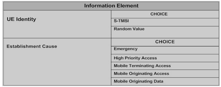 | Figure 6. Connection request message format [5] |
In this message, UE set the value of the value of UE identity and establishment cause information elements. The values for both these information elements are obtained from higher layer such as NAS. In UE-Identity, if paging and higher layer IMSI are matched then this value of IMSI should be configured for the message. If RRC does not get any UE identity from higher layers then RRC select a random value for UE identity between 1 to 240. The value of establishment cause is also shown in the above figure. The establishment cause value is obtained from NAS. The relation of establishment case with NAS message is shown in figure 7.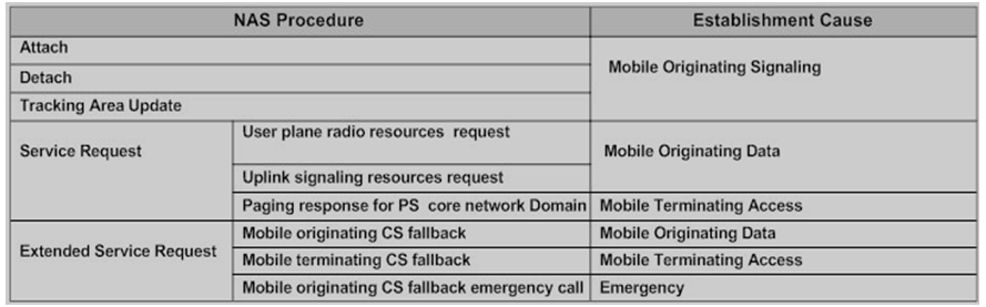 | Figure 7. Relationship of NAS and RRC establishment IE [5] |
When the network receives the connection request message, the eNodeB decode it and check the validity of the UE (User Equipment) identity information element, if it not valid then network send the connection to reject message to the UE. The connection reject message only contains wait time information element for the T302 timer. UE can send connection request message on the same cell after the expiry of this timer. The format of connection of connection rejects message shown in figure 8. | Figure 8. Connection reject message format [5] |
If the networks validate the UE-identity then eNodeB will send connection setup message to the UE, and RRC configures the lower layers and moves to the connected state. The following figure 9 shows the connection setup complete message format.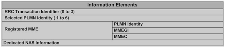 | Figure 9. Connection setup complete [5] |
When the network receives the connection setup complete message, the UE then configure the SRB1 (Signaling Radio Bearer Type 1), SRB2 (Signaling Radio Bearers Type 2) and also other procedures are performed like security and integrity protection, connection reconfiguration, and then the connection is established between UE and eNodeB. The default configuration of SRB1 and SRB2 is shown below in figure 10.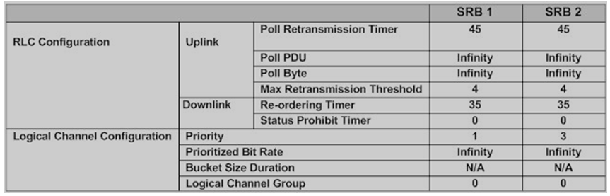 | Figure 10. Default configuration of SRB1 and SRB2 [5] |
5. Connection Establishment Procedure at Network Side
When UE (User Equipment) want to communicate with the network, RRC (Radio Resource Control) connection must need to be established. The state diagram of connection established procedure at network side is shown figure 11 below;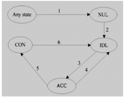 | Figure 11. Connection establishment state diagram [13] |
ACC->IDLWhen the T400 timer expired and eNodeB does not receive the connection complete message from the UE (User Equipment), then this transition takes place. There are two reasons for this transition [13];Ÿ The UE does not receive random access preamble response from the eNodeB.Ÿ RRC connection request is lost in the air and network does not receive and therefore RRC layer of the eNodeB return to IDL state.CON->IDLThis transition takes place because of four reasons [13];Ÿ When network sends security mode, command and the physical link of the underlying network fails due to some error.Ÿ The RLC (Radio Link Control) layer retransmission procedure attempted maximally to receive the connection setup complete, a security mode command and connection reconfiguration complete and these messages lost in the air.Ÿ The network send a security mode command, and UE receive it, but its integrity check failed at PDCP (Packet Data Convergence Protocol) layer of UE side, then transition from CON to IDL.Ÿ When NodeB receive connection release message from EMM (EPS Mobility Management) layer, then transition from CON to IDL state takes place.The message sequence diagram of connection establishment at eNodeB side is shown figure 12 below;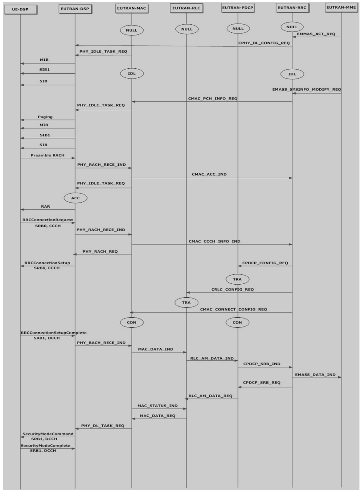 | Figure 12. Connection establishment MSC (Message Sequence Chart) at eNodeB side [13] |
Initially, all the layers are at the NULL state of eNodeB. EMM (EPS Mobility Management) layer send the message to RRC layer to activate it. The RRC layer then configures the lower layers like RRC and MAC (Medium Access Control), and these two layers entered into the IDL state. After configuration of MAC, RRC sends request to MAC layer to send system information and paging message to a UE. |If the system information is changed, EMM (EPS Mobility Management) layer inform RRC layer of eNodeB (Evolved Node B) via CMAC_PCH_INFO_REQ message. The RRC layer then informs MAC (Medium Access Control) to send system information again. After this RRC and MAC move to IDL state. At UE side, after the completion of PLMN (Public Land Mobile Network) search and cell search, it receives the system information and paging message. After this, UE starts random access preamble sequence to the eNodeB. When the RRC layer of eNodeB receives the preamble and validates it. The RRC layer sends a message CMAC_RANDOM_ACC_RES to the MAC layer and informs it to send random access response to the UE. The RRC layer at eNodeB side start T400 timer and move from IDL to ACC state. At UE side, on receiving the random access response, RRC send connection request message to the eNodeB on CCCH (Common Control Channel). MAC layer on the eNodeB side receive the message and transfer this message to RRC by primitive of CMAC_CCCH_INFO_IND. The network then sends connection setup to the UE. After this, when RRC layer at eNodeB receive the connection complete message before the expiry of T400 timer, then it performs the configuration of RLC (Radio Link Control) layer and MAC (Medium Access Control) layer and stop the timer T400. The RRC layer now moves from ACC to CON State.When connection establishment procedure is completed, then SRB1 (Signaling Radio Bearer Type 1) is established. To start data communication, UE need to establish SRB2 (Signaling Radio Bearer Type 2) and DRBs (Data Radio Bearers).These configurations are required from the eNodeB side. First, EMM from eNodeB side activates security through EMMA_SECURITY_IND primitive on UE at PDCP (Packet Data Convergence Protocol) layer for data transmission. The eNodeB from EMM layer then send RRC connection reconfiguration message to UE through SRB1 on DCCH (Dedicated Control Channel). When UE receive this message at RRC layer, it establishes SRB2 (Signaling Radio Bearer Type 2) and DRBs. Now UE is ready for Data communication [13].
6. Connection Establishment Procedure in Femtocell Network
The F-BS (Femto-Base Station) are used inside the door and connected to the a mobile core network through fixed broadband internet. The power and service of F-BS (Femto-Base Station) are smaller as compared to M-BS (Mobile-Base station). The F-BS (Femto-Base Station) are cheaper than that of M-BS (Mobile- Base Station) [15]. Therefore, the installation of F-BS can reduce the cost as compared to the installment of M-BS. The following figure 13 shows the architecture of F-BSs.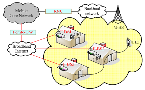 | Figure 13. Femtocells network architecture [15] |
When a UE (User Equipment) is in an idle state and receive a paging message or initiation of connection establishment procedure from higher layer [15]. UE send RRC connection establishment request to eNodeB, then network sends RRC connection setup message to the UE or sends RRC connection to reject message to UE, which contains redirection info IE (Information Element) which help UE to make connection establishment with other eNodeB (Evolved Node B). The following figure 14 shows the failure and success cases of connection establishment procedure.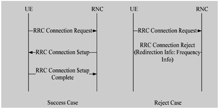 | Figure 14. Connection establishment procedure [15] |
When UE for the first time send RRC connection establishment request to eNodeB, it checks the database for it and if accessible F-BSs are present in the nearby location of UE. eNodeB send RRC connection to reject message to UE with redirection info IE. This IE contains all list of accessible F-BSs. The UE then send RRC connection request message to one of the accessible F-BS. If no response is returned, then RRC connection request is sent to other F-BS, and RRC connection setup and RRC connection complete messages are followed to complete the connection establishment [5] [7] [15]. The following figure 15 shows connection establishment procedure with F-BS (Femto-Base Station).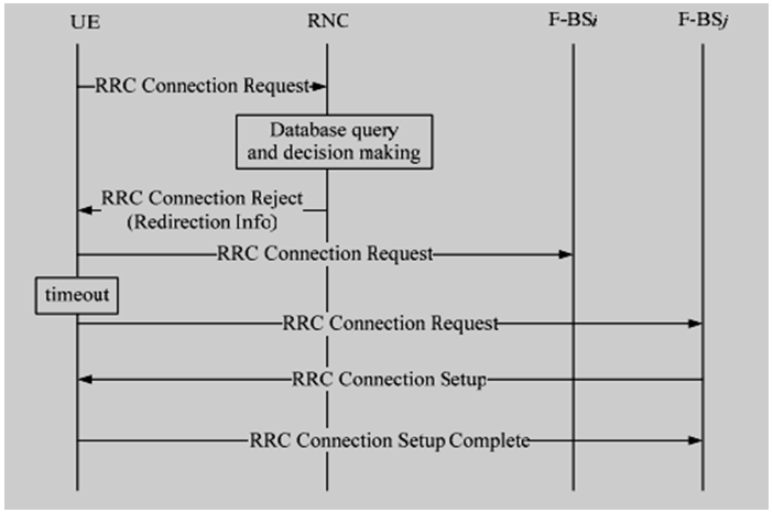 | Figure 15. Succeeded to redirection info to accessible UE [15] |
UE have performed maximum attempt to connect it to any F-BS but failed. This failure is because UE does not detect any F-BSs or F-BSs do not respond due to any reason. In this case, UE sends connection request message to the eNodeB again. This time, eNodeB will detect second received request, therefore, will accept the message, and connection will be established. The procedure is depicted in the following figure 16.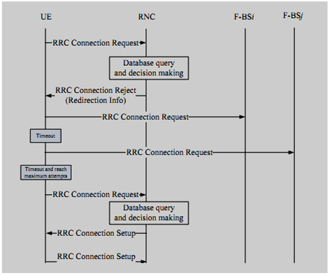 | Figure 16. Failed to redirect to UE [15] |
When eNodeB receive the RRC connection request message, it checks if it is the first message or not. If it is not then F-BSs are not accessible so eNodeB accept the request. If it is the first message, the eNodeB send RRC connection rejects message with redirection info IE which contains a list of nearby F-BSs to UE [15]. The following figure shows the algorithm.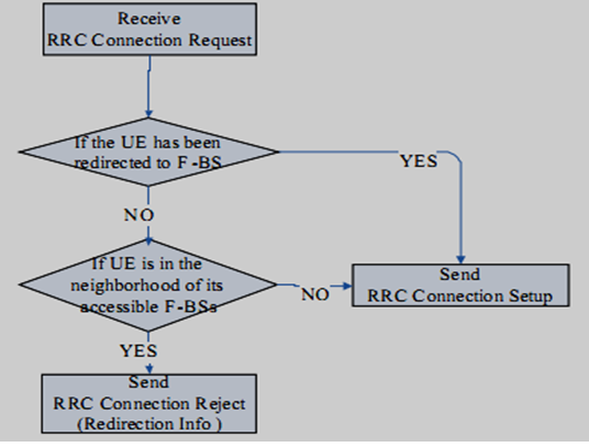 | Figure 17. Algorithm that eNodeB accepts the request or sends redirection to UE [15] |
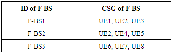
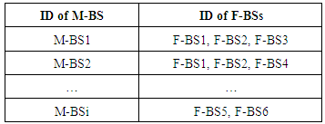
There is two table used in the algorithm used by the eNodeB. Access control table and overlay relationship table. The access control table is maintained manually when users use the F-BSs (Femto-Base Stations) service. The overlay contains the relationship between M-BSs (Mobile- Base Stations) and F-BSs. This table is maintained manually or scanning the environment for F-BS and report to the core network. When UE send RRC connection request message, eNodeB knows about the UE on which it is camped. Therefore, eNodeB find the nearby F-BSs from the tables and send the list via redirection info IE. The tables are shown below;Table 1. Access Control Table
 |
| |
|
Table 2. Overlay Relationship Table
 |
| |
|
Two procedures are used to select F-BS from the list of F-BSs contains in redirection info, the random selection procedure, and position based selection procedure [15].In random selection policy, UE randomly selects F-BS from redirection info which contains a list of F-BS if the selected F-BS accept the request then the connection is established, and if F-BS reject the connection, then another F-BS is randomly selected from the list. The selection procedure is repeated for the maximum attempt, or no F-BS is left on the list. The limitation on attempts is required to overcome the connection delay.In position based selection, location about F-BS and UE is obtained from GPS (Global positioning system). Therefore, eNodeB will determine the exact position of F-BS and UE camped on it. If no F-BS is found, then M-BS accept the connection. Experimentally, it is verified that position based policy is better than random policy because connection delay in position based policy is smaller than random policy. In position based policy exact positions of UE and F-BS are determined the. Therefore, a number of attempts of connection establishment requests is less than a random policy which selects F-BS in a blind manner.
7. Conclusions and Future Work
RRC is one of the important layers of the LTE (Long Term Evolution) stacks. Connection establishment is one of the procedures handled by this entity. Connection establishment procedure must be performed before starting any data communication. In this paper, a connection establishment flow charts, MSCs (Message Sequence Charts) and algorithms are reviewed. The review includes discussion about connection establishment related to UE, eNodeB, and femtocells. LTE is very complex and is full of research opportunities, and our survey reveals different research areas.1). Enhancements in existing flow charts and MSCs (Message Sequence Charts) of connection establishment procedures related to new standards of 3gpp and its simulation on SDL TTCN.2). Research on other procedures of RRC (Radio Resource Control) layer like handover, measurement reporting, etc3). Research on other layers of the stack like RLC (Radio Link Control) Layer, PDCP (Packet Data Convergence Protocol) layer, MAC (Medium Access Control) layer and NAS (Non-Access Stratum).4). Research on a comparison of connection establishment procedure with other technologies and generations of wireless technology.
References
| [1] | Mudit Ratana Bhalla and Anand Vardhan Bhalla, "Generations of Mobile Wireless Technology: A Survey" in International Journal of Computer Applications, Vol. 4, August 2010, pp. 0975-8887. |
| [2] | Lawrence Harte, Introduction to Mobile Telephone Systems, 2nd edition, United States of America: ATLOS Publishing Inc, 2006, pp.34-64. |
| [3] | Christopher Cox,” System Architecture and Evolution" in An Introduction to LTE, 1st edition, United Kingdom: John Wiley and Sons Ltd, 2012, pp.21-44. |
| [4] | 3GPP, 3rd Generation Partnership Project; Technical Specification Group Radio Access Network; Evolved Universal Terrestrial Radio Access (E-UTRA) and Evolved Universal Terrestrial Radio Access Network (Release 9), 3GPP TS 36.300, June 2009. |
| [5] | 3GPP, 3rd Generation Partnership Project; Technical Specification Group Radio Access Network; Evolved Universal Terrestrial Radio Access (E-UTRA); Radio Resource Control (Release 9), 3GPP TS 36.331, Jan.2010. |
| [6] | Christopher Cox, "Power-On and Power-off Procedures" in An Introductions to LTE, 1st edition, United Kingdom: John Wiley and Sons Ltd, pp.173-188, 2012. |
| [7] | Ce Liu, Demin Zhang, Xiaowen Li and Fengming Jiao, "The research of RRC connection establishment and co-simulation of SDL and TTCN", IEEE Computing, Control and Industrial Engineering, Vol. 2, pp. 216-219, Aug. 2011. |
| [8] | 3GPP, 3rd Generation Partnership Project; Technical Specification Group Radio Access Network; Evolved Universal Terrestrial Radio Access (E-UTRA); User Equipment (UE) procedures in idle mode(Release 9), 3GPP TS 36.304, Jan.2010. |
| [9] | 3GPP, 3rd Generation Partnership Project; Technical Specification Group Radio Access Network; Evolved Universal Terrestrial Radio Access (E-UTRA) Medium Access Control (Release 9), 3GPP TS 36.321, Jan.2010. |
| [10] | 3GPP, 3rd Generation Partnership Project; Technical speciation group radio access networks; 3G home node B study item technical report (Release 8). 3GPP TR 25.820. |
| [11] | 3GPP, 3rd Generation Partnership Project; Technical Specification Group Radio Access Network; Evolved Universal Terrestrial Radio Access (E-UTRA) Radio Link Control (Release 9), 3GPP TS 36.322, Jan.2010. |
| [12] | 3GPP, 3rd Generation Partnership Project; Technical Specification Group Radio Access Network; Evolved Universal Terrestrial Radio Access (E-UTRA); Packet Data Convergence Protocol (Release 9), 3GPP TS 36.323, Jan.2010. |
| [13] | Wen Kai and Lu Lihua, "Research and implementation of LTE RRC connection establishment process of network side" in IEEE Educational and Information Technology, Vol. 2, pp. V3-229-V3-232, Sept. 2010. |
| [14] | Kalliokulju, "User plane architecture of 3rd generation mobile telecommunication network", IEEE Networks, Vol. 2, pp. 270-278, Oct. 1999. |
| [15] | Yu-Ching Hsu, Show-Show Tzeng and Ching-Wen Huang, "A Study for Connection Establishment in Femtocell Network", IEEE Parallel Processing Workshops, pp. 114-118, Sept. 2011. |
| [16] | Hsin-Yi Lee and Yi-Bing Lin, “A caching scheme for Femtocell selection”, IEEE Communications Letters, Vol. 14, pp. 27-29, Jan. 2010. |
| [17] | 3GPP, 3rd Generation Partnership Project; Technical speciation group services and system aspects; Telecommunication management; Self-organizing networks (SON); Concepts and requirements (Release 10), 3 32.500, Sept. 2010. |

 Abstract
 Reference
 Full-Text PDF
 Full-text HTML