-
Paper Information
- Paper Submission
-
Journal Information
- About This Journal
- Editorial Board
- Current Issue
- Archive
- Author Guidelines
- Contact Us
Journal of Wireless Networking and Communications
p-ISSN: 2167-7328 e-ISSN: 2167-7336
2016; 6(2): 47-55
doi:10.5923/j.jwnc.20160602.03

Inverted E-shape Microstrip Antenna for Bandwidth and Gain Enhancement
 Abstract
 Reference
 Full-Text PDF
 Full-text HTML
Hind S. Hussain
Department of Physics, College of Science, Al-Nahrain University, Baghdad, Iraq
Correspondence to: Hind S. Hussain, Department of Physics, College of Science, Al-Nahrain University, Baghdad, Iraq.
| Email: |  |
Copyright © 2016 Scientific & Academic Publishing. All Rights Reserved.
This work is licensed under the Creative Commons Attribution International License (CC BY).
http://creativecommons.org/licenses/by/4.0/

Microstrip antennas are very promising due to their integration capability, but lack of bandwidth. In many communication applications they need to operate in broadband. A high gain wideband microstrip patch antenna is presented in this paper. The design adopts contemporary techniques; direct coaxial probe feeding, inverted patch structure with air-filled dielectric, and E-shaped patch. The integration of these techniques leads to a new patch antenna with a low profile as well as useful operational features, as the broadband and high gain. The proposed antenna shows a wideband behavior. It is found that antenna attains impedance bandwidth of 41.5% (VSWR ≤ 2) in the frequency range (2.1GHz-3.2GHz). The achievable gain is 9.4dB at 2.42GHz. A parametric study has been carried out in the investigation. A conventional rectangular patch antenna using RT-Duroid 5880 with εr = 2.2 and thickness 1.6mm at operating frequency 2.42GHz is used as a reference. The simulated results obtained from MW-Office 2006 simulation software.
Keywords: Microstrip Patch Antenna, Wideband, VSWR, Slot Loaded
Cite this paper: Hind S. Hussain, Inverted E-shape Microstrip Antenna for Bandwidth and Gain Enhancement, Journal of Wireless Networking and Communications, Vol. 6 No. 2, 2016, pp. 47-55. doi: 10.5923/j.jwnc.20160602.03.
Article Outline
1. Introduction
- During the recent years, the wideband microstrip antenna has its wide application in many communication systems. One of the important applications is the wireless communication system (1.8GHz-5.6GHz) [1-5]. Microstrip antenna is an attractive candidate for wireless communication system due to their numerous advantages such as low cost, light weight and easily printed onto the circuit board. However, these antennas exhibit a few serious limitations such as low impedance bandwidth and gain in their conventional form [6-8]. Hence, several researchers reported numerous techniques to improve these restrictions, especially enhancing the impedance bandwidth [9, 10]. These alterations include, cutting slots in the basic shapes [11], changing the shape of the geometry [12], or using multi-layer techniques [13, 14].Bandwidth enhancement can also be achieved by modifying the feed networks (elements) such as meandered probe [15] or changing the probe to T-shape [16] or L-shape [17]. However, many of these geometries use multiple metal/dielectric layers for enhancing the impedance bandwidth which poses fabrication and assembly problems. However, the bandwidth and the size of an antenna are generally mutually converting properties, that is, improvement of one of the characteristics normally results in degradation of the other. Recently, an E-shaped patch antenna [18] and U-slotted patch antenna [19] have been designed for wireless communications. However, both of these patch substrate are non-inverted and achievable gains of both antennas are below 8.5 dB. In this paper, a new inverted E-shape patch antenna is investigated for the gain and bandwidth enhancement. The design employs contemporary techniques, namely, the coaxial probe feeding, inverted patch, and E- patch techniques to meet the design requirement. A wider impedance bandwidth and better gain are achieved compared to the design reported in [18].
2. Theoretical Analysis of Rectangular Patch Antenna
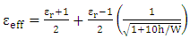
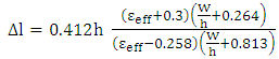
- To design a rectangular patch microstrip antenna, the following parameters such as dielectric constant of the substrate (εr), the operating frequency (f), and the height of the substrate (h) should be considered for calculating the length and the width of the patch(a) Width of the patch (W) The width of the patch can be
 , for good performance W=1.5L is chosen. For TM01 mode, the initial length of the patch can be calculated by the following equation [20]:
 | (1) |
 | (2) |
 | (3) |
 | (4) |
 | (5) |
 | (6) |
 | (7) |
3. Geometry of Conventional Rectangular Patch Microstrip Antenna RPMSA
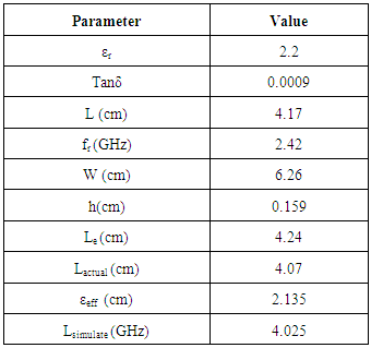
- A conventional rectangular patch microstrip antenna, RPMSA operating at TM01 mode was designed at operating frequency 2.42GHz. The radiating patch has dimensions (L x W) and is printed on a dielectric substrate of thickness h and relative permittivity ɛr. In this study, RT Duroid 5880 dielectric substrate with εr=2.2, loss tangent =0.0009 is used. The patch dimensions are (4.025x6.26) cm2. The thickness of the substrate, h= 0.159cm (=0.019 λd). The radiating patch is excited by a coaxial feed probe at proper feed location (xf=1.26cm, yf=3.13cm) which is obtained after many simulation trails in order to get good impedance matching. Figure 1 shows the geometric parameters of this design.
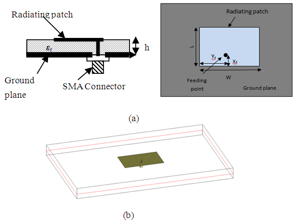 | Figure 1. Conventional RPMSA (a) side (to the left) and top (to the right) view of geometric parameters, (b) 3D view of antenna configuration using MWO software |
|
4. Geometry of Inverted E-shape Rectangular Patch Microstrip Antenna (ERPMSA)
- The conventional RPMSA was modified in order to enhance the bandwidth and the gain of the antenna. Figure 2 depicts the layout of the proposed antenna. The structure incorporates an inverted and slotted radiating patch, air substrate and a coaxial probe connected to the patch. The inverted rectangular patch, with dimension of 4.346cm x 7.03cm is supported by a superstrate with dielectric permittivity ɛr (2.2) and thickness h (0.159 cm). An air filled dielectric substrate with thickness h1 (1cm) is sandwiched between the superstrate and a ground plane. Two parallel slots are etched on the patch to form an E-shape patch as shown in Figure 2-a, where, l and w are the length and width of the slots respectively. The patch is fed by a coaxial probe along the centerline (x-axis) at a distance fP (0.76cm) from the edge of the patch as shown in Figure 2-b. Table 2 shows the optimized design parameters obtained for the proposed patch antenna. The dimensions of the slotted patch have little change than the patch in the conventional RPMSA.
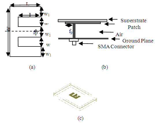 | Figure 2. Geometry of proposed microstrip patch antenna (a) top (to the left) and side (to the right) view. (b) 3D of antenna configuration using MW office view |
|
5. Results and Discussion
- The proposed antennas have been designed and simulated using MW-Office 2006, Version 7 which is a method of moments (MoM) based electromagnetic (EM) software. Each proposed antenna is discussed as follows:
5.1. Conventional RPMSA
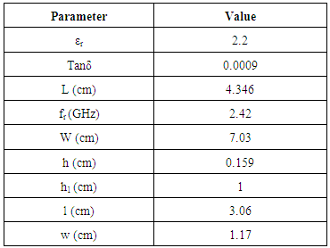
- A conventional RPMSA was first designed as a reference. Figure 3 gives the characteristics of the conventional RPMSA. It can be observed that a very good impedance matching obtained at 2.42GHz, near the center of Smith chart as shown Figure 3-a which gives a very low power return to the feeding as shown in Figure 3-b. The value of return loss at 2.42GHz is -20.4dB. Again, this value of return loss shows a very high impedance matching at 2.42GHz. The frequency band produced is 5MHz as shown in Figure 3-c. The percentage impedance bandwidth is 2%, which is considered very low value. The gain produce from the antenna at 2.42GHz is 7.84dB as shown in Figure 3-d. Since a microstrip patch antenna radiates normal to its patch surface, the elevation for Eθ at ϕ = 90° (H-plane) and Eϕ at ϕ = 0° (E-plane) would be important. Figure 4 shows the normalized value of the radiation pattern for both principal planes at f=2.42GHz which gives the half-power beamwidth (HPBW) at -3dB. The HPBW for Eθ is 102.3o and for Eϕ is 64.7o. It can be noticed that in the H-plane Eθ component and in the E-plane Eφ have symmetrical shapes with respect to the zenith (θ=0o).
 | Figure 3. The characteristics of conventional RPMSA: (a) Smith chart, (b) return loss [S11], (c) VSWR curve, and (d) gain curve of a conventional RPMSA |
 | Figure 4. Normalized radiation pattern for both principal planes at f=2.42GHz for conventional RPMSA |
5.2. Inverted E-shape Rectangular Patch Microstrip Antenna (ERPMSA)
- The effects of various key parameters on slotted antenna design are studied. Characteristic of an antenna can be optimized by properly choosing the length of the slot (l), the width of the slot (w), and the air gap thickness (h1). Note that the patch dimensions, its dielectric height, and the feeding probe position are not changed through the work. When one parameter was changed, the other two parameters were kept constants.
5.2.1. Effect of Air Gap Thickness
- The effect of variation of air gap thickness (h1) on the antenna performance (Smith Chart, VSWR, Return Loss, and Gain) is shown in Figure 5. The air gap thickness represents the feeding probe height, which is increased while keeping the other parameters constant (l=3.06 cm, w=1.17 cm). Increasing the air gap results in increasing the inductance of the feeding pin and decreases its capacitance, which is very clear shown in Fig 5-a, the curves move toward the inductive region of the Smith chart as the air gap increase. Also increasing h1, the impedance bandwidth increase as shown in Figure 5-b. The optimum values for the impedance matching, VSWR, and return loss curves are these when the air gap is 1cm as shown in Figure 5-a,b, and c respectively, so it is considered as an optimum value. The gain at f=2.42GHz is 9.41dB, as shown in Figure 5-d.
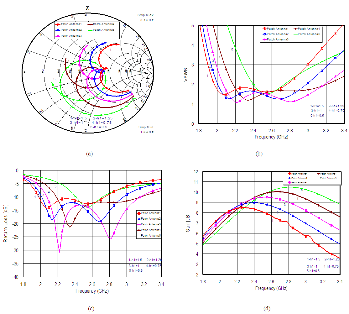 | Figure 5. The characteristics of inverted ERPMSA at different air gap width, h: (a) Smith chart, (b) VSWR curve, (c) return loss [S11], and (d) gain curve |
5.2.2. Effect of Slot Dimensions (length x width)
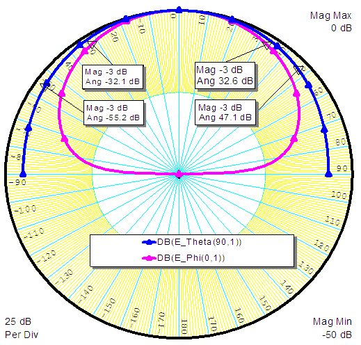
- In general, the presences of slots in the radiating patch restrict the patch currents, and give a capacitive load which compensate the inductance of the excitation probe, results a bandwidth improvement. The effect of both the slot length and width is studied here.(i) Effect of slot width: the effect of variation of slot width (w) on the antenna performance (Smith Chart, VSWR, Return Loss, and Gain) is shown in Figure 6. The slot width increased while keeping the ther parameters constant (h1=1cm, l=3.06cm). Increasing the slot width results in increasing the impedance bandwidth. Although the impedance bandwidth at w=1.56cm is larger than that at w=1.17cm, but the impedance matching at w=1.17cm is better than that at w=1.56, as shown in Figure 6-a,b and c, so w=1.17cm is chosen as an optimized slot width. It can be observed that the gain increase as the slot width increase as shown in Figure 6-d.(ii) Effect of slot length: the effect of variation of slot length (l) on the antenna performance (VSWR, Smith Chart, Return Loss, and Gain) is shown in Figure 7, the slot length increased while keeping the other parameters constant (h1=1cm, w=1.17cm). It can be noticed that as the slot length increase, the impedance matching curve move toward the inductive region of the Smith chart as shown in Figure 7-a, this is due to increasing the current path around the slot which means increasing the inductive load of the radiating patch.The best impedance matching, VSWR, and return loss, curves are these when l=3.06cm, as shown in Figure 7-a, b, and c respectively, so it is used as an optimum value. The slot length has no effect on the gain curve as shown in Figure 7-d. The Antenna is optimized based on the results obtained in section 2. The aim of the optimization is to obtain better gain and bandwidth. The varied parameter specifications after optimization are shown in table 2.The characteristics (VSWR, Smith Chart, Return Loss, and Gain) of the optimum design are shown in Figure 8. A high impedance matching is obtained as shown in Figure 8-a. The simulated impedance bandwidths of 41.5% from 2.1 GHz to 3.2 GHz is achieved at VSWR≤2 as shown in Figure 8-b. Two closely excited resonant frequencies at 2.22 GHz and at 2.8 GHz is achieved as shown in Figure 8-c. The gain produced at 2.42GHz is 9.41dB as shown in Figure 8-d while the gain produced from the conventional RPMS is 7.84dB with 2% bandwidth. Figure 9 shows the normalized value of the radiation pattern for both principal planes (Eθ and Eφ) at f=2.42GHz which gives the HPBW at -3dB . The HPBW for Eθ is 68o and for Eϕ is 54o. It can be noticed that in the H-plane component and in the E-plane Eφ have symmetrical shapes with respect to the zenith (θ=0o). Figure 10 shows the current distribution and the electric field at the surface of the proposed antenna.
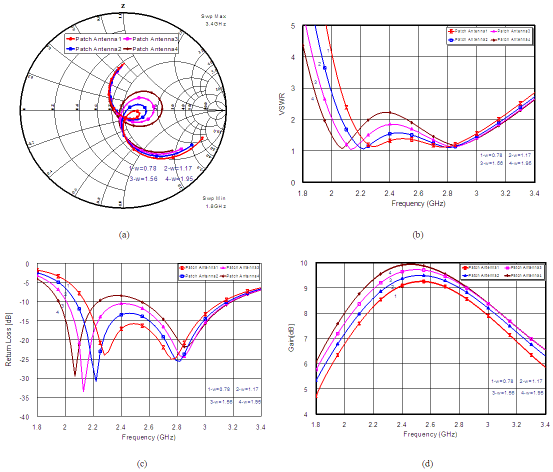 | Figure 6. The characteristics of inverted ERPMSA at different slot width, w: (a) Smith chart, (b) VSWR curve, (c) return loss [S11], and (d) gain curve |
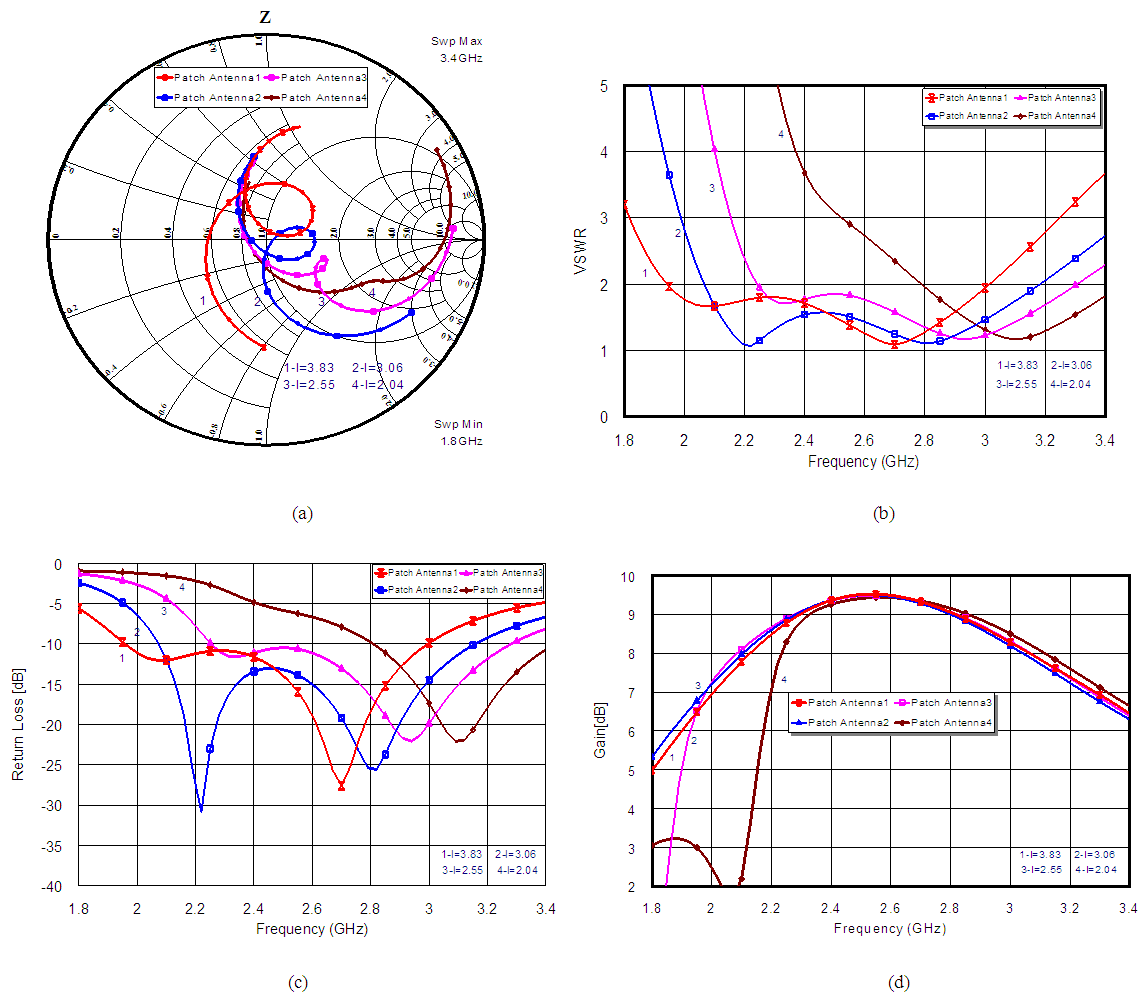 | Figure 7. The characteristics of inverted ERPMSA at different slot length, l: (a) Smith chart , (b) VSWR curve , (c) return loss [S11], and (d) gain curve |
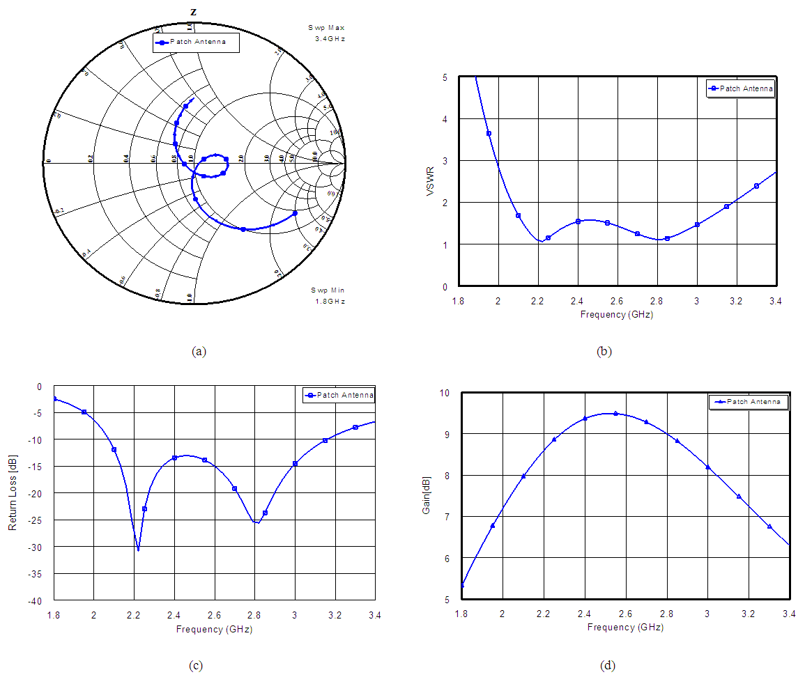 | Figure 8. The antenna performance of the optimum Inverted ERPMSA: h1=1cm, l=3.06cm, and w=1.17cm |
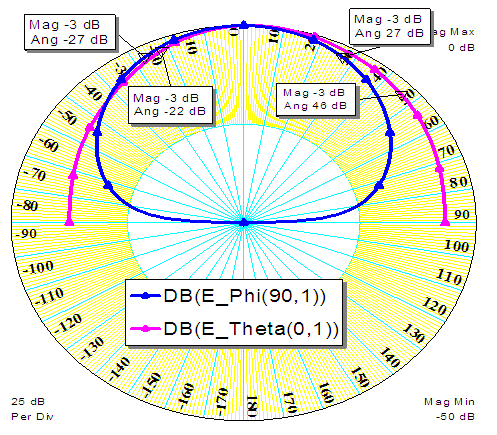 | Figure 9. Normalized radiation pattern for both principal planes at f=2.42 GHz for the optimum Inverted E RPMSA |
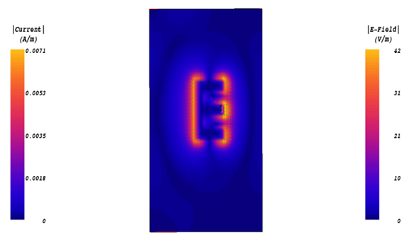 | Figure 10. T the surface current distribution and the electric field at 2.42 GHz for the optimum Inverted ERPMSA |
6. Conclusions
- This paper presents the radiation performance of two types of antenna: a conventional RPMSA and Inverted E-shape rectangular patch microstrip antenna. The radiation performances of proposed geometries have been compared. The conventional RPMSA offer impedance bandwidth of 2% with maximum gain of 7.84dB at 2.42GHz. The proposed inverted E-shape microstrip antenna integrates four techniques together: Coaxial probe feed, thick air substrate, and slotted patch with inverted structure. The proposed antenna offers a wide impedance bandwidth of 41.5% (covering from 2.1 to 3.2 GHz at VSWR≤ 2), symmetric radiation pattern, and high gain of 9.41dB at 2.42GHz.