Charles U. Ndujiuba, Augustus E. Ibhaze
Electrical & Information Engineering, Covenant University, Ota, Nigeria
Correspondence to: Charles U. Ndujiuba, Electrical & Information Engineering, Covenant University, Ota, Nigeria.
| Email: |  |
Copyright © 2016 Scientific & Academic Publishing. All Rights Reserved.
This work is licensed under the Creative Commons Attribution International License (CC BY).
http://creativecommons.org/licenses/by/4.0/

Abstract
Orthogonal Frequency Division Multiplexing (OFDM) is a special case of FDM, which is implemented in digital communication systems. In this technology, multiplexing is applied to independent signals, which are sub-sets of one main signal, and applied to independent channels (sub-carriers) of a bandwidth. Here a user utilizes all sub- carriers to transmit its data. The questions here are: In OFDM can we modulate each sub-carrier differently from one another to enhance the overall integrity of the transmitted signal? If so, what determines the type of modulation technique that is suitable for the individual channels (sub-carriers)? These are the questions we seek to answer in this work, using simulation results to illustrate our theoretical analysis. We use bit error rate (BER) and data throughput as the metric for measuring the performance of the system.
Keywords:
FDM, OFDM, Sub-carriers, BER, Channel State Information (CSI), QPSK, QAM
Cite this paper: Charles U. Ndujiuba, Augustus E. Ibhaze, Dynamic Differential Modulation of Sub-Carriers in OFDM, Journal of Wireless Networking and Communications, Vol. 6 No. 1, 2016, pp. 21-28. doi: 10.5923/j.jwnc.20160601.03.
1. Introduction
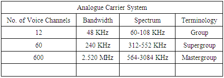
These days communication requires a very high rate with high reliability. Two major difficulties that hinder reliable communication via high rate wireless communication systems are bandwidth limitation of communication channels and multipath fading. To surmount these difficulties in analogue transmission, the basic principle of multi-carrier transmission, can be used, accomplished by means of Frequency Division Multiplexing (FDM) technology. In FDM, independent signals, produced by different users are carried by independent sub-carriers of a given bandwidth. Each user or signal source is allocated a channel (sub-carrier) for the duration of the transmission, and each channel can be modulated by a modulation technique different from the other channels, without affecting their quality of performance. The modulation technique is usually customized to the type of information.In analog transmission, signals are commonly multiplexed using frequency-division multiplexing (FDM), in which the carrier bandwidth is divided into sub-channels of different frequency widths, each carrying an independent signal at the same time in parallel. Each individual channel occupies a finite frequency range, typically some multiple of a given base frequency. Traditional terrestrial microwave and satellite links employ FDM. Although FDM in telecommunications is being reduced, several systems will continue to use this technique, namely: broadcast & cable TV, and commercial & cellular radio.Figure 1 illustrates the main concepts of a typical FDM scheme. This process can continue until the available bandwidth on the cable or microwave link is exhausted.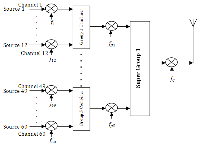 | Figure 1. FDM Scheme |
Table 1. Capacity of an FDM scheme
 |
| |
|
The RF spectrum must be shared, yet every day there are more users for that spectrum as demand for communications services increases, hence the increase in the quest for better spectral efficiency. This can be achieved by employing digital modulation schemes, because they have greater capacity to convey large amounts of information than analog modulation schemes. OFDM is a digital multi-carrier modulation scheme in which a single high rate data stream is divided into multiple low rate data streams. These data streams are then modulated using subcarriers which are orthogonal to each other. In this way the symbol rate on each sub channel is greatly reduced, and hence the effect of inter symbol interference (ISI) due to channel dispersion in time caused by multipath delay spread is reduced. Each subcarrier is modulated with a conventional digital modulation scheme (such as QPSK, 16QAM, etc.) at low symbol rate.The low-pass equivalent OFDM signal is expressed as: [1-3]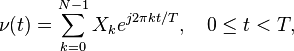 where
where  are the data symbols,
  is the number of sub-carriers, and
  is the OFDM symbol time. The sub-carrier spacing of
  makes them orthogonal over each symbol period; this property is expressed as: [1-3]
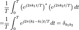 where
where  denotes the complex conjugate operator and
  is the Kronecker delta.Since each subcarrier has a lower information rate, the data symbol periods in a digital system will be longer, adding some additional immunity to impulse noise and reflections. The OFDM scheme differs from traditional FDM in the following interrelated ways:1. Multiple carriers (called subcarriers) carry one information stream, and2. The subcarriers are orthogonal to each other.Figure 2 illustrates the concepts of OFDM and its similarity with the FDM scheme [4, 5]. The high data rate serial input bit stream is fed into serial to parallel converter to get low data rate output parallel bit stream. Input bit stream is taken as binary data. The low data rate parallel bit stream is modulated in Signal Mapper. Modulation can be BPSK, QPSK, etc. The OFDM symbols are fed to Inverse Fast Fourier transform so that each subcarrier is assigned with a specific frequency. In this block, orthogonality in subcarriers is introduced. In IFFT, the frequency domain OFDM symbols are converted into time domain OFDM symbols. This OFDM signal is allowed to pass through digital to analogue converter (DAC). In DAC the OFDM signal is fed to RF power amplifier for transmission. If there is frequency mismatch between transmitter and receiver local oscillators, frequency offset occurs. Then the signal is allowed to pass through additive white Gaussian noise channel (AWGN channel) [5].
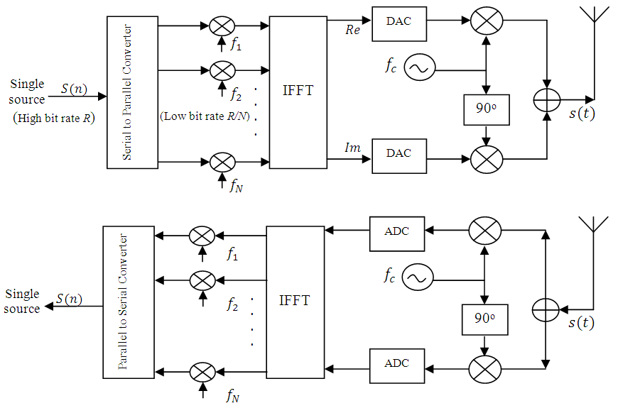 | Figure 2. OFDM Scheme |
An OFDM carrier signal is the sum of a number of orthogonal sub-carriers, with baseband data on each sub-carrier being independently modulated commonly using some type of quadrature amplitude modulation (QAM) or phase-shift keying (PSK). This composite baseband signal is typically used to modulate a main RF carrier. S[n] is a serial stream of binary digits. By inverse multiplexing, these are first demultiplexed into parallel streams, and each one mapped to a (possibly complex) symbol stream using some modulation constellation (QAM, PSK, etc.). Note that the constellations may be different, so some streams may carry a higher bit-rate than others [6, 7]. An inverse FFT is computed on each set of symbols, giving a set of complex time-domain samples. These samples are then quadrature-mixed to pass band in the standard way. The real and imaginary components are first converted to the analogue domain using digital-to-analogue converters (DACs); the analogue signals are then used to modulate cosine and sine waves at the carrier frequency, fc, respectively. These signals are then summed to give the transmission signal, s[t] [7].In an OFDM transmission system, each subcarrier is attenuated individually under the frequency-selective and fast fading channel. The channel performance may be highly fluctuating across the subcarriers and varies from symbol to symbol [6].If the same fixed transmission scheme is used for all OFDM subcarriers, the error probability is dominated by the OFDM subcarriers with highest attenuation resulting in a poor performance. Therefore, in case of frequency selective fading the error probability decreases very slowly with increasing average signal-to-noise ratio (SNR). This problem can be mitigated if each subcarrier can be allocated a different modulation scheme based on the measured channel conditions. This allows subcarriers to be dynamically allocated modulation schemes based on the SNR of each subcarrier. Those subcarriers with a low SNR can be allocated to use BPSK (1 b/s/Hz) or to transmit no data at all. Subcarriers with a high SNR can transmit higher modulation schemes such as 256-QAM (8 b/s/Hz) allowing a higher system throughput [8].This will substantially improve the performance and data throughput of an OFDM system. For example if the subcarriers that will exhibit high bit error probabilities in the OFDM symbol to be transmitted can be identified and excluded from data transmission, the overall BER can be improved in exchange for a slight loss of system throughput. OFDM also has some drawbacks. Because OFDM divides a given spectral allotment into many narrow subcarriers each with inherently small carrier spacing, it is sensitive to carrier frequency errors, which may be caused by Doppler shift in the channel, or by the difference between the transmitter and receiver local oscillator frequencies. This frequency offset introduces inter-carrier interference in the OFDM symbol [9,10]. We propose a differential modulation method in order to combat channel with deep fading. Bits are allocated on each subcarrier so that the overall transmit power is minimized under a fixed bit error rate (BER). This project investigates differential modulation methods for combating the effects of channel fading.
2. The System Model
Accurate channel state information (CSI) (channel coefficient), is required at the transmitter to achieve the benefits. Imperfect CSI arises from noisy channel estimates, which may also be outdated due to a delay in getting the CSI Understanding the channel allows for manipulation of the phase and amplitude of each subcarrier at the transmitter in order to decide the appropriate modulation type for the subcarrier. A known signal is sent to the target device that enables it to build a picture of the channel environment. The target device sends back the channel characteristics to the transmitter. The transmitter can then apply the correct phase and amplitude adjustments based on the resulting SNR [11].
2.1. Impact of Channel Correlation on Channel State Information (CSI)
The performance of an OFDM system is critically dependent on the quality of independent multiple subcarriers. It is well known that channel correlation will downgrade the performance of an OFDM system, especially its capacity. Channel correlation is a measure of similarity or likeliness between the channels. In the extreme case that if the channels are fully correlated, then the OFDM system will have no difference from a single-carrier communication system.The most general formula for calculating channel capacity in the case where channel coefficients are either known or unknown at the transmitter is the Shannon capacity formula [11]: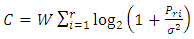 | (1) |
where W is the bandwidth of each sub-channel, r is the rank of the channel coefficient matrix H.  is the received power at each Rx antenna from the
  channel, for
  during the considered symbol time slot.i) Unknown Channel Coefficients at the Transmitter● Single carrier channel: In this case, we have
 the channel capacity is calculated
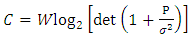 | (2) |
At SNR  for instance, the normalized capacity of the single antenna channel is C/W = 6.658 bits/s/Hz.● Receive diversity: In this case,
  and
and 
 where
where denotes the transposition operation. The channel capacity is calculated as
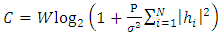 | (3) |
Assuming that  then we have
 | (4) |
For N = 2 and SNR p = 2dB, we have C/W = 7.6511 bits/s/Hz. We can see that the normalized capacity in this case is larger than that in the case of channels with single Tx and Rx antennas.● Transmit diversity: In this case,  and
and  the channel capacity is calculated as
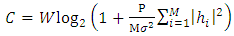 | (5) |
Assuming that  then we have
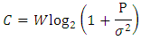 We see that the capacity of the channel where channel coefficients are fixed and unknown at the transmitter is the same as that of the single antenna channel regardless of the number M of Tx antennas.Hence, for M = 2, N = 1 and SNR p = 2dB, we have C/W = 6.658 bits/s/Hz.ii) Known Channel Coefficients at the TransmitterThe channel capacity can be increased if channel coefficients are known at the transmitter. In this case, the transmitted power is assigned unequally to the Tx antennas, such that a larger power is assigned to a better sub-channel and vice versa.● Transmit diversity: In this case,
  and
and  the channel capacity is calculated as
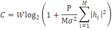 Assuming that
 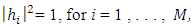 then we have
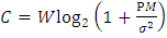 | (6) |
Hence, for M = 2, N = 1 and SNR p = 2dB, we have C/W = 7.6511bits/s/Hz which is larger than the channel capacity when the channel coefficients are unknown at the transmitter (C/W = 6.658 bits/s/Hz).The traditional fixed resource allocation is not optimal, since the scheme is predetermined regardless of current channel conditions. On the other hand, dynamic resource allocation assigns a dimension adaptively to the users based on their channel gains. Due to the cause of time-varying nature of the wireless channel, dynamic resource allocation makes full utilization of multiuser diversity to achieve higher performance.The block diagram of this system is shown in Figure 3. The channel estimation and mode selection are done at the receiver side and the information is sent to the transmitter using a feedback channel.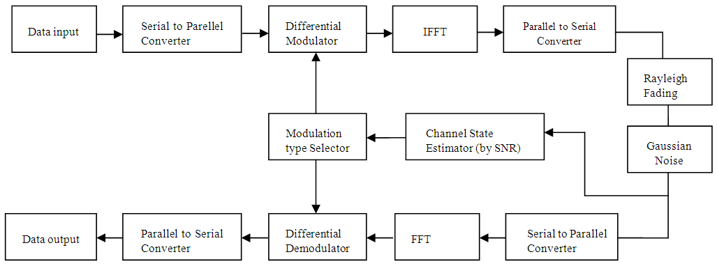 | Figure 3. Block diagram of dynamic differential modulation scheme |
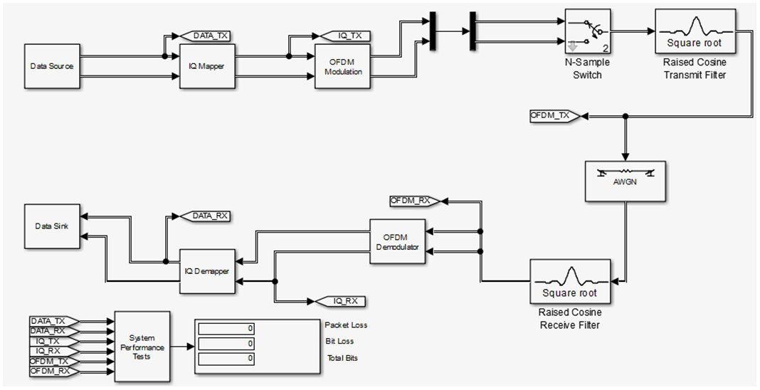 | Figure 4. Simulation setup of the differential modulation scheme |
The channel estimator is used to estimate the instantaneous SNR of the received signal. Based on the instantaneous SNR calculated, the best mode will be chosen for the next transmission frame. This task is done by the mode selector block. At the transmitter the adaptive modulator block consists of different modulators which are used to provide different modulation modes. The switching between these modulators will depend on the instantaneous SNR. The goal of differential modulation is to choose the appropriate modulation mode for transmission in each sub-carrier, given the local SNR, in order to achieve good trade-off between spectral efficiency and overall BER.The approach in setting the switching threshold is based on using the lowest quality subcarrier, i.e; the lowest value of SNR, to control the selection of modulation mode. If a suitable modulation mode or code rate is selected the overall BER can be closer to the BER target and the throughput of the system will be higher.The switching algorithm used for the modulation schemes are presented in Tables 1 to 4. The design parameters used in the simulation are shown in Table 5.In this modulation scheme data will be constantly transmitted even though the channel is in deep fades. If the channel quality is very bad, a robust modulation mode will be used and when the channel quality is good a spectrally efficient modulation will be used.The increase in performance of the OFDM radio system can be measured by higher data rates, improved spectral efficiencies and the increase in channel capacity of the system.
3. Simulation, Results, and Discussion
In this simulation, the metric for performance measurement of the differential modulation is in terms of BER. The benefits of the proposed scheme is highlighted by comparing the BER rate of the differential modulation to fixed modulation system, i.e, system with the same modulation for all the subcarriers.Firstly, the performance of MQAM system is investigated, with the result shown in Figure 5. Then the system with all MPSK is investigated, as shown in Figures 6-10. Finally, the system a combination of MQAM and MPSK was simulated, and the results compared with the fixed modulation systems. The results are shown in Figure 11.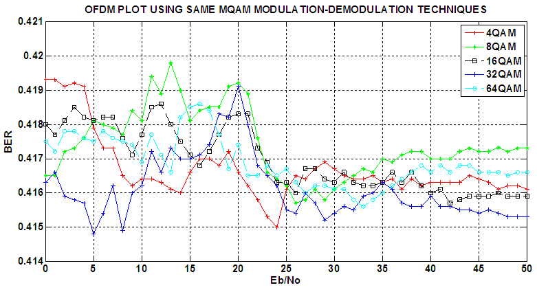 | Figure 5. BER performance of fixed MQAM modulation |
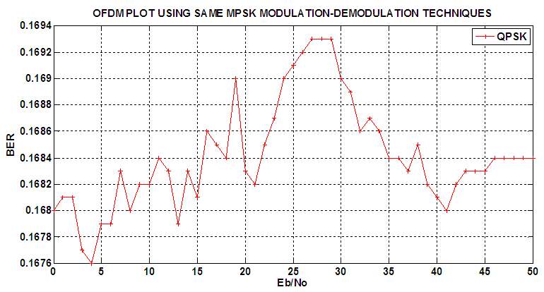 | Figure 6. BER performance of 4PSK system |
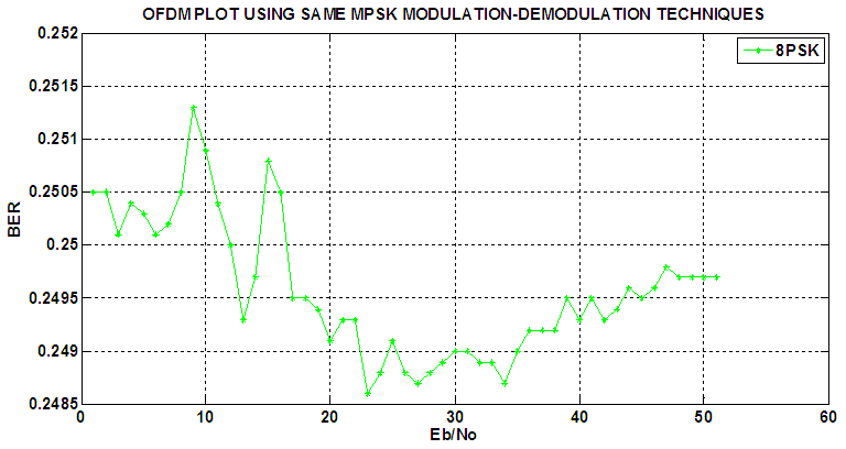 | Figure 7. BER performance of 8PSK system |
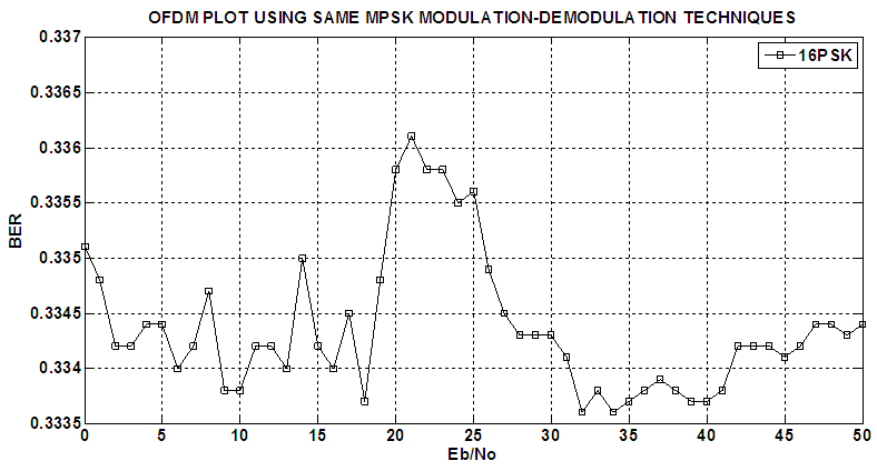 | Figure 8. BER performance of 16PSK system |
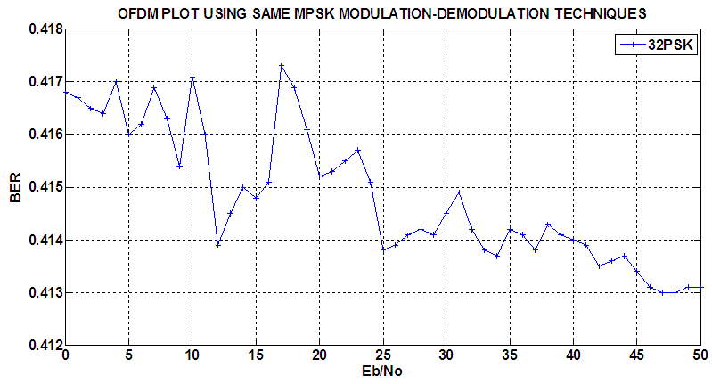 | Figure 9. BER performance of 32PSK system |
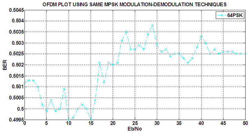 | Figure 10. BER performance of 64PSK system |
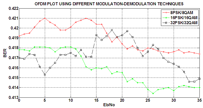 | Figure 11. BER performance of the differential modulation (MQAM/MPSK) |
In the differential modulation system the BER performance was better compared to the performance of fixed modulation systems. Figure 11 shows the performance of the differential modulation scheme. It can be seen that the BER performance of the differential scheme is at least equal to QPSK for SNR range 1 dB till 15 dB. For SNR more than 15 dB the BER performance is better than all the fixed MPSK system. However the SNR required to meet the BER target is quite high which is more than 25 dB.
4. Conclusions
In this paper, the performances of adaptive transmission scheme for OFDM have been investigated. The advantage of employing adaptive transmission scheme is described by comparing their performance with fixed transmission system. A better adaptation algorithm is used to improve the throughput performance. This algorithm utilizes the average value of the instantaneous SNR of the subcarriers in the switching parameter. The results show an improved throughput performance with considerable BER performance.As investigated in this paper, OFDM systems potentially possess a better BER performance when subcarriers are modulated with different modulation schemes than those with the same modulation. This benefit is described by comparing the results of the proposed scheme with the fixed scheme. In this work, this algorithm utilizes the average value of the instantaneous SNR of the subcarriers as the switching parameter. The results show an improved BER performance.
References
| [1] | J. Faezah and K. Sabira, ‘Adaptive modulation for OFDM systems’, Intl. Journal of Communication Networks and Information Security (IJCNIS) vol. 1, no.2 August 2009. |
| [2] | Sigen Ye, Rick S. Blum, Leonard J. Cimini Jr., ‘Adaptive modulation for variable-rate OFDM systems with imperfect channel information. |
| [3] | Sutanu Ghosh, ‘Performance Evaluation on the Basis of Bit Error Rate for different order of Modulation and different length of subchannels in OFDM system’, Intl. Journal of Mobile Network Communications & Telematics (IJMNCT) vol.4, no.3, June 2014. |
| [4] | Cheong Yui Wong, Roger S. Cheng, ‘Multiuser OFDM with Adaptive Subcarrier bet and power allocation’, IEEE Journal on Selected Areas in Communications, vol. 17, no.10, October 1999. |
| [5] | Nitha V. Panicker, Sukesh Kumar A., ‘BER Performance Evaluaation of Different Digital Modulation Schems for Biomedical Signal Transceivers, under AWGN and fading Channel conditions’, Intl. Journal of Engineering and Advanced Technology (IJEAT) ISSN:2249-8958, vol.3 iss.5, June 2014. |
| [6] | Charles U. Ndujiuba, Oluyinka Oni, Augustus E. Ibhaze, ‘Comparative Analysis of Digital Modulation Techniques in LTE 4G systems’, Journal of Wireless Networking and Communications, 2015, 5(2): 60-66 DOI:10.5923/j.jwnc 20150502.02. |
| [7] | M.A. Masud, M. Samsuzzaman, M.A. Rahman, ‘Bit Error Rate Performance Analysis on Modulation Techniques of Wideband Code Division Multiple Access’, Journal of Telecommunications vol.1, iss 2, March 2010. |
| [8] | Umesh Sharma, ‘Comparative study of Digital Modulation techniques in WIMAX’, Intl. Journal of Engineering and Innovation Technology (IJEIT) vol.2, iss2, August 2012. |
| [9] | Ch. Girish Kumar, K. Sripath Roy, ‘Development and Implementation of OFDM Transceiver for WLAN Applications’, Intl. Journal of Engineering Research and Applications ISSN: 2248-9622, vol.4, iss.7 (version 1), July 2014, pp101-106. |
| [10] | Sangeeta Jajoria, Sajjan Singh, S.V.A.V. Prasad, ‘Analysis of BER Performance of OFDM system by Adaptive Modulation’, Intl. Journal of Recent Technology and Engineering (IJRTE), ISSN: 2277-3878, vol. 1, iss. 4, October 2012. |
| [11] | Charles Uzoanya Ndujiuba, Oluwadamilola Oshin, Nsikan Nkordeh, ‘MIMO Deficiencies due to Antenna Coupling’ Intl. Journal of Networks and Communications 2015, 5(1) 10-17, DOI:10.5923.ijnc.20150501.02. |

 Abstract
 Reference
 Full-Text PDF
 Full-text HTML