Md. Mainul Islam Mamun1, Joarder Jafor Sadique2, Shaikh Enayet Ullah1
1Department of Applied Physics and Electronic Engineering, Rajshahi University, Rajshahi, Bangladesh
2Department of Electronics and Telecommunication Engineering, Begum Rokeya University, Rangpur, Bangladesh
Correspondence to: Joarder Jafor Sadique, Department of Electronics and Telecommunication Engineering, Begum Rokeya University, Rangpur, Bangladesh.
| Email: |  |
Copyright © 2014 Scientific & Academic Publishing. All Rights Reserved.
Abstract
In this paper, a comprehensive study has been made to explore the suitability of spatial modulation (SM) transmission scheme to enhance performance of a 4×4 MIMO configured multicarrier wireless communication system. In such system, modern concatenated channel coding scheme utilizing Repeat and Accumulate (RA) and SPC Codes, MIMO-OFDM, MIMO-OFDMA with block type resource allocation, DFDMA (Distributed FDMA) and LFDMA (Localized FDMA) Subcarrier assignment and DFT-spreading have been used. With developed system performance evaluative simulator in perspective of BERs estimation using MATLAB, it is obserable from simulation results that 3-D encoded Spatial Modulation aided MIMO OFDMA wireless communication system shows robust performance in QAM digital modulation, Linear Minimum Mean Square Error signal detection and Distributed FDMA Subcarrier assignment schemes.
Keywords:
Spatial modulation, Distributed FDMA, Localized FDMA, Subcarrier assigning, Orthogonal frequency - division multiple access (OFDMA), Signal detection scheme, Bit error rate, DFT-spreading
Cite this paper: Md. Mainul Islam Mamun, Joarder Jafor Sadique, Shaikh Enayet Ullah, Performance Assessment of a 3-D Encoded Spatial Modulation Aided Multicarrier MIMO Wireless Communication System, Journal of Wireless Networking and Communications, Vol. 4 No. 3, 2014, pp. 76-84. doi: 10.5923/j.jwnc.20140403.02.
1. Introduction
Spatial Modulation (SM) has established itself as a beneficial transmission paradigm, subsuming numerous members of the MIMO system family. An extensive research activities have been made on SM achieving sufficient maturity to motivate its comparison to state-of-the-art MIMO communications, as well as to inspire its application to other emerging wireless systems such as relay-aided, cooperative, small-cell,optical wireless, and power-efficient communications. The SM–MIMO transmission exloits Transmit antenna (TA)-specific property of the wireless channel on the uniqueness of each transmit-to-receive wireless link for data communication using information-driven antenna-switching mechanism.The SM-MIMO provides higher throughput, simplification of transmitter and receiver design, reduction of transmitted power.On recent literature reviewing, it has been known that the conventional multiuser MIMO systems with a large number (tens to hundreds) of antennas at the base station (BS) referred as Massive MIMO/Large-scale MIMO systems are getting increased research attention because of their advantages in terms of very high spectral efficiencies/sum rates, increased reliability, and power efficiency. The large-scale MIMO technology is being considered as a potential technology for future fifth generation (5G) wireless systems. Although the SM-MIMO was not considered as a competing MIMO technique in the LTE-A standard but it can be considered in spectral- and energy-efficient 5G cellular networks [1, 2].Orthogonal frequency-division multiple access (OFDMA) has received much attention as a promising radio air interface technology for next-generation wireless systems. It provides high data rates with supporting of good coverage and mobility. OFDMA can simultaneously satisfy the communication requirements of multiple mobile stations through by allocation of one or more subcarriers to each mobile station at the same OFDMA symbol time unit. The OFDMA physical layer protocol has been adopted in many infrastructure based wireless networks such as IEEE 802.16 and 3rd Generation Partnership Project (3GPP) Long-term evolution-Advanced (LTE-A) [3]. In OFDMA, the available spectrum is divided into a number of narrowband orthogonal subcarriers that can be dynamically allocated to mobile stations (MSs), thus providing on demand and increased data rates. The use of orthogonal subcarriers allows their spectrum to overlap; hence, the over all spectrum eficiency is increased. Moreover, the insertion of a cyclic preix (CP) at the beginning of the OFDM symbol can signiicantly reduce intersymbol interference (ISI) in cases of multipath propagation [4].The present study highlights on the performance evaluative study of a MIMO-OFDMA wireless communication system utilizing various signal processing schemes such as 3-D encoding based spatial modulation, modern error correction channel coding, DFT-spreading and signal detection. A brief description is given below.
2. 3-D Encoded Spatial Modulation
In Figure 1 the encoding mechanism of SM–MIMO is illustrated for four transmitting antennas. 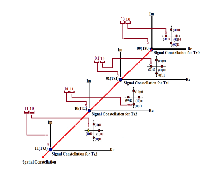 | Figure 1. Conceptual diagram for 3-D Spatial Diagram |
The encoder processes the information bits in blocks of four bits each. In the first channel use shown in Fig. 1, the block of bits to be encoded is ‘‘1110.’’ The first 2 bits, ‘‘11,’’ determine the single active transmitting antenna(TA), TX3, while the second 2 bits,‘‘10,’’determine the transmitted PSK/QAM symbol. The activated TA may change every channel use according to the input information bits. Thus, TA switching is an effective way of mapping the information bits to TA indices and of increasing the transmission rate. The information bits are modulated onto a 3-D constellation diagram, which generalizes the known 2-D (complex) signal-constellation diagram of PSK/QAM modulation schemes [1].
3. Modern Error Correction Scheme
In such channel coding schemes, Repeat and Accumulate (RA) and SPC Codes have been used.In RA, a powerful modern error-correcting coding scheme, an information block u (usually binary) of length 2048 is repeated 2 times and permuted by an interleaver of length 4096. The interleaved binary data block z is passed through a truncated rate-1 two-state convolutional encoder whose output x is the Repeat and Accumulate encoded binary data and is given by x = zG, where G is an 4096 × 4096 matrix with 1s on and above its main diagonal and 0s elsewhere. In SPC channel coding, the transmitted binary bits are rearranged into very small codewords consisting of merely two consecutive bits. In such coding, (3, 2) SPC code is used with addition of a single parity bit to the message u = [u0,u1] so that the elements of the resulting codeword x = [x0,x1,x2] are given byx0 = u0, x1 = u1 and: x2 = u0  u1where
  denotes the sum over GF(2) [5].
4. Subcarriers Assigning Scheme and PAPR Reduction
In this present study, both OFDM and OFDMA transmission techniques have been used. In OFDM, all subcarriers are used for transmitting the symbols of a single mobile user. In OFDMA systems, subcarriers are partitioned and assigned to multiple mobile users. Unlike the downlink transmission, each mobile user in uplink uses a subset of subcarriers transmit its own data. The rest of the subcarriers, not used for its own data transmission,will filled with zeros. In block type sub channel allocation in OFDMA, the subset consists of 256 subcarriers. In localized FDMA subcarriers assigning scheme, 256 symbols are used in a OFDMA block. Additional two blocks with each block containg 384 zeros are added to the front and back ends of the data block forming an OFDMA block od 1024 symbols. In case of distributed FDMA subcarriers assigning scheme, three zero are inserted between two consequtive symbols to form an. OFDMA block od 1024 symbols. In case of DFT–spreading under LFDMA,256–point DFT is used for spreading to 256 symbols. Additional 768 zeros are added at the end of the output of DFT prior to IFFT operation. The DFT-spreading technique is used in OFDMA for PAPR reduction [6].
5. Signal Detection
A signal model for received signal R, Noise Z, 4 × 4 MIMO channel H, transmitted signal S and signal to noise ratio  can be written as:
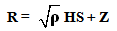 | (1) |
5.1. Zero-Forcing (ZF)
In ZF signal detection, the effect of interference is reduced by pre multiplying the received signal matrix R by the Moore–Penrose pseudo inverse of the channel matrix H defined by H+ as: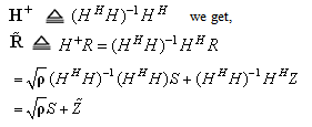 | (2) |
Where, 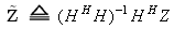 In receiver signal matrix
  , four complex data symbol vector
  and
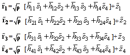
and  , are transmitted simultaneously from four transmitting antenna. In matrix form, we can write-
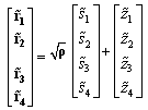 | (3) |
 | (4) |
Equation 4 significantly indicates that the pre multiplied received signal is interference free and consists of merely a vector of transmitted symbols plus a noise vector. In consideration of a single time slot, the location of the maximum absolute value of the receiving signal vector is found out using the  following relation:
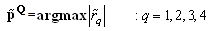 | (5) |
and Q is the transmitting antenna identifier at a specific time slot. Each transmitting antenna is specified for transmitting merely one type of QAM/QPSK digitally modulated signal transmission.
5.2. Linear Minimum Mean Square Error (LMMSE)
In LMMSE signal detection scheme, it is assumed that each transmitted signal  is estimated at the receiver by linearly combining weighted versions of the received signal R, viz.
  | (6) |
The optimum values of the complex weighted matrix W with dimension of 4 × 4 presented in matrix W0 for noise and interference cancellation can be written as: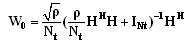 | (7) |
Where, Nt is the number of transmitting antenna and INt is the 4 × 4 identity matrix.On pre multiplication of R with W0 and considering 
 , we get
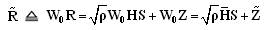 | (8) |
In matrix form, Equation (8) can be written as- 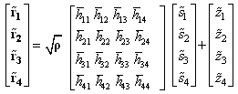 | (9) |
 | (10) |
Normalizing Equation (10) through dividing required term, we get [7], 
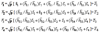 As in each single time slot, merely one signal is transmitted from any one of the four transmitting antenna, proper identification of the transmitting antenna is made through estimating maximum absolute value of the modified form of receiving signal vector
  using the following relation:
 | (12) |
and Q is the transmitting antenna identifier at a specific time slot.
6. Communication System Model
The block diagram of the 3-D encoded Spatial Modulation aided Multicarrier MIMO wireless Communication system is shown in Figure 2. The synthetically generated binary data are channel encoded using concatenation of two modern codes. The concatenated channel encoded signals are digitally modulated using QAM and QPSK. The digitally modulated symbols are fed into spatial modulation aided spatial demultiplexing section to produce four data series to be transmitted from antennas after executing various signal processing steps (Serial to parallel conversion, subcarrier mapping (with LFDMA and DFDMA)/DFT spreading, OFDM/OFDMA modulation, Cyclic prefixing and parallel to serial conversion. In receiving section, all the transmitted signals are detected with linear signal detection schemes and the detected signals are subsequently sent up to the serial–to–parallel (S/P) converter and after that they are processed with cyclic prefix removing scheme, then fed into OFDM/OFDMA demodulator which performs FFT operation on each OFDM/OFDMA block. The FFT operated OFDM/OFDMA block are processed for subcarrier demapping/DFT dispreading, parallel–to–serial conversion and fed into spatial demodulation aided spatial multiplexing. The multiplexed complex symbols are digitally demodulated, channel decoded to recover the transmitted data [6].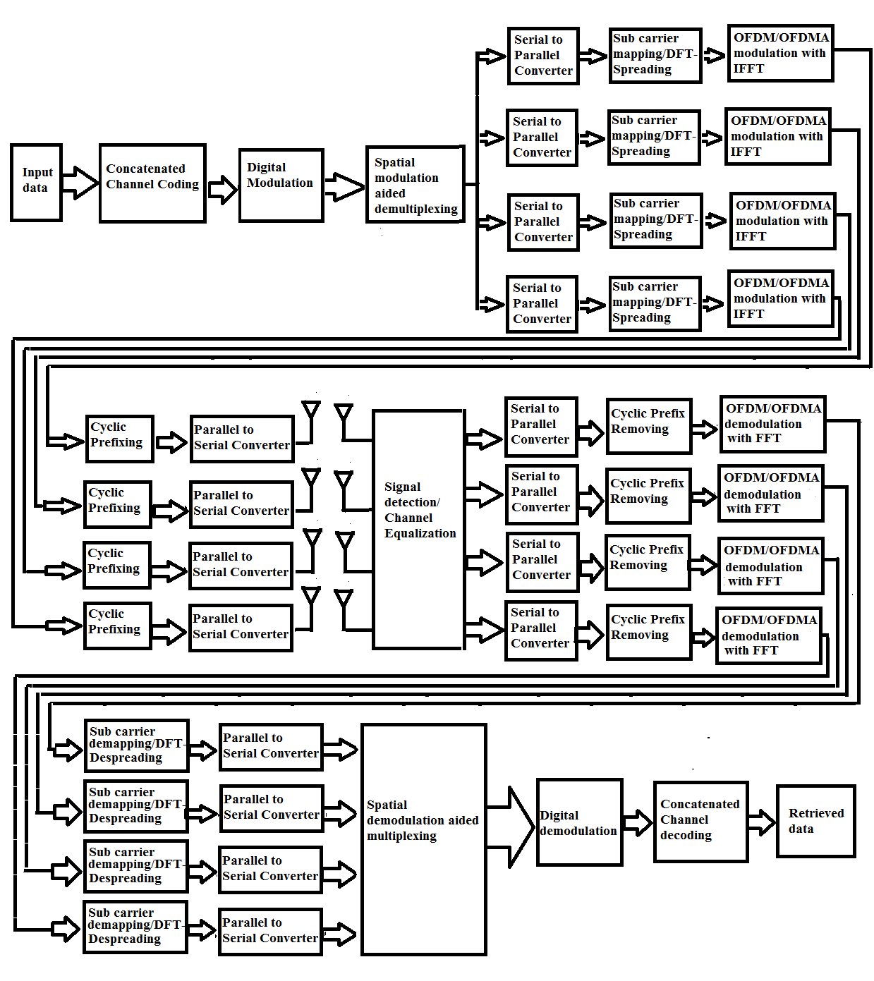 | Figure 2. Block diagram of 3-D encoded Spatial Modulation aided Multicarrier MIMO wireless Communication system |
7. Results and Discussion
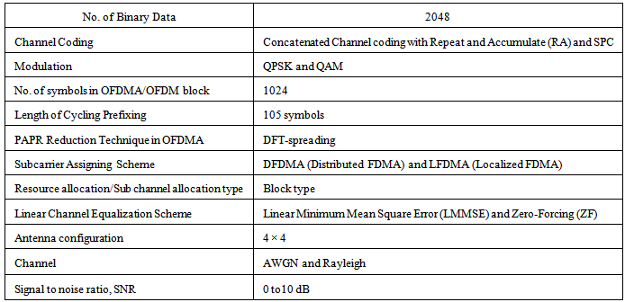
In our simulations, we have assumed that the signals are transmitted in a quite identical Rayleigh fading environments and the channel state information (CSI) is available at the receiver. The simulation results depicted in Figure 3 through Figure 7 illustrate system performance in terms of BER in 3-D encoded Spatial Modulation aided Multicarrier MIMO wireless Communication system. The Simulation study has been made using MATLAB 2012a based on the parameters given in Table 1.Table 1. Summary of the simulated model parameters
 |
| |
|
In Figure 3, BER performance curves for linear MMSE and Zero–Forcing signal detection are well defined. In Figure 3, a significant improvement of system performance can also be seen with linear MMSE and QAM digital modulation. In low SNR value region, the slope of BER versus SNR curves for Zero –Forcing signal detection steepens and incurs a significant degradation in the BER performance. For a typically assumed SNR value of 0.5 dB, the multicarrier system shows 5.20 dB improved performance in QAM with LMMSE as compared to QPSK with ZF. In Figure 4, it is noticeable that implementation of block type resource allocation has a quite acceptable impact on system performance enhancement. The BER performance in ZF signal detection is not well discriminate from each other in case of QPSK and QAM digital modulations.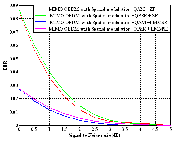 | Figure 3. BER performance of a 3-D encoded Spatial Modulation based MIMO OFDMA system with implementation of modern channel coding and channel equalization schemes |
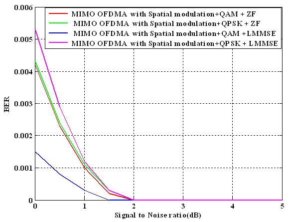 | Figure 4. BER performance of a 3-D encoded Spatial Modulation based MIMO OFDMA system with implementation of modern channel coding, block type resource allocation strategy and channel equalization schemes |
At SNR value of 0.5 dB, the multicarrier system shows 5.59 dB and 4.77 dB improved system performance in QAM with LMMSE as compared to QPSK with LMMSE and QPSK with ZF. In QAM with LMMSE, the BER approaches zero at 1.5 SNR value.In Figure 5, it is observable that the multicarrier system with adaptation of localized FDMA sub carrier assigning scheme shows 4.77 dB improved performance in QAM with LMMSE as compared to ZF with QPSK at a SNR value of 0.5 dB. A 1% BER, a SNR gain of 0.70 dB is achieved in QAM with LMMSE as compared to QPSK with ZF. In Figure 6, it is noticeable that the system performance gap for ZF receiver in QAM and QPSK is low. In case of LMMSE receiver, a sharply observable performance gap is existing for QAM and QPSK. Due to PAPR reduction in DSP spreading, probably, the system performance degrades in QAM with LMMSE as compared to such considerable factors with localized FDMA subcarrier and block type resource allocation schemes. Reasonably, a low system performance improvement is found to have a value of 2.28 dB in QAM with LMMSE as compared to ZF with QPSK at a SNR value of 0.5 dB.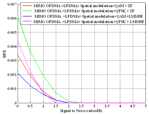 | Figure 5. BER performance of a 3-D encoded Spatial Modulation based MIMO OFDMA system with implementation of modern channel coding, localized FDMA subcarrier assigning strategy and channel equalization schemes |
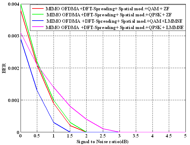 | Figure 6. BER performance of a 3-D encoded Spatial Modulation based MIMO OFDMA system with implementation of modern channel coding, DFT-spreading and channel equalization schemes |
In Figure 7, it is quite obvious that the multicarrier system shows a quite satisfactory performance with implementation of distributed FDMA subcarrier assigining scheme. At identical signal and noise power(0 dB SNR), a 4.26 dB system performance improvement is achieved in QAM with LMMSE as compared QPSK with ZF. At 0.5 dB, the system performance is degraded from 4.26 dB to 3.76 dB. At 1% BER, a SNR gain of 0.50 dB and 0.32 dB are achieved in QAM with LMMSE as compared to QPSK with ZF and QAM with ZF.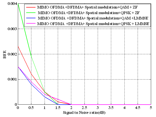 | Figure 7. BER performance of a 3-D encoded Spatial Modulation based MIMO OFDMA system with implementation of modern channel coding, Distributed FDMA subcarrier assigning strategy and channel equalization schemes |
8. Conclusions
Spatial modulation (SM), an effective and robust multiple antenna transmission approach has been applied to multi carrier MIMO wireless communication system. Such modulation scheme can be used in 5G compatible massive/large MIMO wireless communication systems. The system performance under implementation of spatial modulation in independent and identically distributed Rayleigh flat fading channels has been assessed critically with various resource allocation and PAPR reduction schemes. The system performance degrades in ZF receiver and improves in LMMSE receiver. However, on the basis of simulation results, it can be concluded that the 4 × 4 multi antenna supported and 3-D encoded spatial modulation based MIMO OFDMA is a robust system under implementation of concatenated modern channel coding, QAM digital modulation, LMMSE signal detection and distributed FDMA subcarrier assigining schemes.
References
| [1] | Marco Di Renzo, Harald Haas, Ali Ghrayeb, Shinya Sugiura and Lajos Hanzo, 2014: Spatial Modulation for Generalized MIMO: Challenges, Opportunities,and Implementation, Proceedings of the IEEE, vol. 102, no. 1, pp.56-103. |
| [2] | T. Lakshmi Narasimhan, P. Raviteja, and A. Chockalingam, 2014: Large-Scale Multiuser SM-MIMO Versus Massive MIMO |
| [3] | Jaesung Park, Jiyoung Chung, Hyungyu Lee and Jung-Ryun Lee, 2014: Design and Performance Evaluation of a Distributed OFDMA-Based MAC Protocol for MANETs, The Scientific World Journal, Hindawi Publishing Corporation, vol. 2014, pp.1-15. |
| [4] | Panagiotis K. Gkonis,Maria A. Seimeni, Nikolaos P. Asimakis, Dimitra I. Kaklamani, and Iakovos S. Venieris, 2014: A New Subcarrier Allocation Strategy for MIMO-OFDMA Multicellular Networks Based on Cooperative Interference Mitigation, The Scientific World Journal, Hindawi Publishing Corporation,vol. 2014 pp.1-9. |
| [5] | Giorgio M. Vitetta, Desmond P. Taylor, Giulio Colavolpe, Fabrizio Pancaldi and Philippa A. Martin, 2013: Wireless Communications Algorithmic Techniques, John Wiley and Sons Ltd, United Kingdom. |
| [6] | Yong Soo Cho, Jaekwon Kim, Won Young Yang, Chung G. Kang, 2010: MIMO-OFDM Wireless Communications with MATLAB, John Wiley and Sons (Asia) Pte Limited, Singapore. |
| [7] | Jerry R. Hampton, 2014: Introduction to MIMO Communications, Cambridge University Press, United Kingdom. |
 Abstract
 Reference
 Full-Text PDF
 Full-text HTML