Kshirasagar Naik, Veluppillai Mahinthan
Dept. of Electrical and Computer Engineering, University of Waterloo, ON, Canada, N2L3G1
Correspondence to: Kshirasagar Naik, Dept. of Electrical and Computer Engineering, University of Waterloo, ON, Canada, N2L3G1.
| Email: |  |
Copyright © 2014 Scientific & Academic Publishing. All Rights Reserved.
Abstract
the main contribution of this paper is that hitherto unknown special characteristics of Bluetooth co-channel interference are revealed. In a Bluetooth piconet, the channel hop frequency at any instant of time is determined by the Master’s device address and its native clock. In a cluster of two masters of the 79-hop type, average packet error rate is 1/79 (= 1.26%), and it increases by almost 1% for each additional Master up to a reasonably large number, say 40 Masters. By actually implementing the hop selection kernel for the 79-hop system as specified in the Baseband Specification, we carry out experiments. Those experiments reveal that under certain conditions on device addresses and native clocks, interference can be as high as 50% even with just two Masters. We conclude that packet interference rate in a certain cluster of Bluetooth Masters is actually determined by their device addresses and the asynchrony among their native clocks.
Keywords:
Bluetooth, Interference, Device Address, Native Clock
Cite this paper: Kshirasagar Naik, Veluppillai Mahinthan, Impacts of Bluetooth Device Addresses and Native Clocks on Packet Interference in Piconets, Journal of Wireless Networking and Communications, Vol. 4 No. 2, 2014, pp. 42-48. doi: 10.5923/j.jwnc.20140402.02.
1. Introduction
BLUETOOTH technology was developed to provide low power, short-range, low-cost radio links to connect a variety of devices, namely, mobile phones, headsets, and laptops [1]. Bluetooth devices operate in the 2.4GHz license-free Industrial, Scientific, and Medical (ISM) band. The specification allows a device to hop over 79 1-MHz channels for ordinary applications and 40 2-MHz channels for Bluetooth low energy (BLE) applications [2]. In a piconet, data transmission in the CONNECTION state is performed using a channel hopping sequence; to transmit data at the medium access control (MAC) level, devices hop from one frequency to another. As Bluetooth is intended to be used in low-energy, low bandwidth applications, co-channel interference from other Blueooth devices can significantly degrade device performance [4], [5]. El-Hoiydi has given a probabilistic model of packet interference in a cluster of 79-hop system piconets with single slot data packets [4]. The interference model proposed by Naik et al. [5] is based on the concept of probabilistic graphs and it is more general than El-Hoiydi’s model: (i) a cluster of piconets can have both the 79-hop piconets and the earlier 23-hop piconets; and (ii) individual piconets can operate in the single-slot mode or a multi-slot mode. Chakraborty et al. [3] have analyzed the average and worst-case time needed to perform device discovery, while ignoring the impact of cochannel interference. Drula et al. [7] have proposed adaptive energy conserving algorithms for neighbor discovery. The time to perform device discovery and the energy expended in the process will be further increased in the presence of co-channel interference. Shin et al. [6] have studied how the performance of ZigBee networks is impacted by interference from Bluetooth devices.In packet interference models for clusters of Bluetooth piconets, it is assumed that the probability of co-channel interference between two Masters of the 79-hop type in the CONNECTION state is 1/79 (= 1.26%) [4], [5]. However, the channel hopping sequence of a Master is precisely determined by the device address of the piconet’s Master, and the phase in the sequence is determined by the native clock of the Master. In other words, the frequency on which a data packet is transmitted at a given moment in a piconet is determined by the Master’s device address and native clock at that moment. Therefore, it is likely that the probability of packet error between two piconets due to co-channel interference is influenced by the two Master’s device addresses and native clocks. To the best of our knowledge, the topic has not been investigated before.In this paper, we study whether or not the device addresses and native clocks of two Masters make any difference in cochannel packet interference. In other words, we investigate if a certain pair of Masters produces more mutual interference than another pair for certain clock conditions. The result of this study is important in the selection of device addresses as Masters in a personal area network.By means of a software implementation of the frequency selection box, we carried out several experiments to observehow device addresses and native clocks of Masters impactmutual interference. It is observed that under certain conditions on device addresses and native clocks, even just two Masters produce co-channel interference of up to 50% as opposed to the expected low-level of 1.26%. Thus, a certain degree of care must be exercised in the selection of device addresses while forming a personal area network. In addition, there might be a need to redesign the hop selection kernel to alleviate the problem. In summary, the main contribution of this paper is that hitherto unknown special characteristics of Bluetooth co-channel interference are revealed.In Section II, we give a brief outline of the channel hop selection process [1]. The results of our experiments are presented in Section III. Some concluding remarks are given in Section IV.
2. Channel Hop Selection
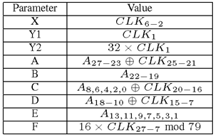
A Bluetooth device address is a 48-bit globally unique number with three distinct parts: 24-bit lower address part (LAP), 8-bit upper address part (UAP), and 16-bit non-significant address part (NAP). The hop selection kernel uses only the lower 28 bits of a device address. Every Bluetooth device has a free-running, 28-bit native clock which determines the timing and hopping of the transceiver. The native clock is neither adjusted nor ever turned off. For synchronization with other units, only offsets are used, that when added to the native clock, provide temporary clocks which are mutually synchronized with other devices. The native clock of a device is denoted by CLKN. The Master’s native clock in a piconet is denoted by CLK. For the Master, obviously, CLK = CLKN, whereas in a slave device CLK = Master’s CLKN. However, since a slave has its own native clock CLKN, a slave calculates the value of CLK by adding a fixed offset to its own CLKN.A block diagram of the hop selection kernel for the 79-hop system is shown in Fig. 1. The hop selection kernel uses the 28 lower bits of a device address and the upper 27 bits of its CLK, and the input parameters to the kernel have been identified in Table 1. In the second column of Table 1, CLKstands for channel clock or the native clock of a piconet’sMaster and A is the 48-bit device address of the Master. In the first column of the same table, the input parameter A is computed by taking the exclusive-or operation on bits 27-23 of the device address and bits 25-21 of CLK. | Figure 1. Hop selection kernel for 79-hop system [1] |
Table 1. Parameters of the Hop Kernel
 |
| |
|
Notice that the XOR operation to the left of the PERM5 block has one input and the output of the first ADD block with five bits and another input B with four bits. In the 79-hop system, the most significant bit (MSB) of the first input (i.e. the output of the first ADD block) is passed on to theoutput without any change, whereas the remaining four bits are XORed with the four bits of the B input. Thus, the MSB of the output of the XOR block is the same as the MSB of the output of the first ADD block.The second XOR block just above PERM5 takes two input parameters, namely Y1 and C. Parameter Y1 is just one bit, whereas C consists of five bits. The five output bits of this XOR block are obtained by performing an XOR operation of Y1 with each of the five input bits of C.The block PERM5 essentially permutes the five input bits, denoted by Z, according to the 14 control bits appearing at its top. The 14 control bits are nine bits from input D and five bits from the output of the XOR block above it. These 14 control bits are denoted by symbols P0 through P13. P0−8corresponds to D0−8, and Pi+9 corresponds to Ci+Y1 for i = 0..4. The details of the permutation block are shown in Fig. 2. The five input bits (Z) are permuted by the 14 control bits in seven stages. At each stage four of the input bits are permuted by two control bits. For example, as shown in Fig. 2, P13 permutes {Z1,Z2} and P12 permutes {Z0,Z3} in stage 1. According to the specification, if a control bit is a ’1’, the input bits are passed on to the output unchanged, if the control bit is a ’0’, the input bits are permuted to produce the output.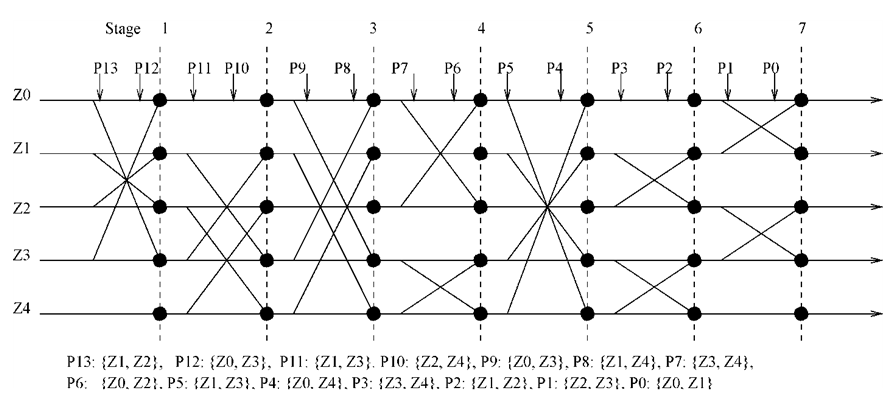 | Figure 2. Details of the PERM5 block in the hop kernel |
The final ADD block sums up the four input parameters with modulo 79 to produce an index into the frequency mapping table. In the mapping table appearing at the extreme right of Fig. 1, the first half contains all even numbered frequencies, whereas the second half contains all the odd numberedfrequencies. In the mapping table, entry ’0’ corresponds to2402 MHz, entry ’1’ corresponds to 2403 MHz, entry ’2’corresponds to 2404 MHz, and so on.
3. Simulation Model and Experiments
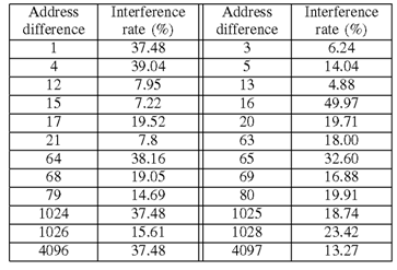
A. Simulation ModelThe hop selection kernel shown in Fig. 1 gave an indication that two Masters are likely to produce identical hop frequencies from time to time depending on their native clocks. Generation of identical hop frequencies at the same time leads to interference of packets. To find out if a certain pair of devices produces more interference than another pair, a discrete-event simulator was developed. One of the most complex tasks in the design of the simulator was implementing the hop selection kernel. In Section II, we have explained the kernel’s parameter values in the CONNECTION state. The complete description of the kernel can be found in The Baseband Specification [1].The implementation of the hop selection kernel was validated against the data obtained from a protocol analyzer. The protocol analyzer captured data packets exchanged between pairs of Bluetooth modules and gave us the following useful details that we used in validating our implementation: CLK value of the channel, the Master’s address, and the frequency on which the packet was transmitted.B. Experimental ResultsIn this section, we describe four experiments and discussthe ensuing results. A model for performing experiments wasderived with two Masters with one slave each. It was assumed that all the four devices were located in such a way that packets from one device in a piconet can potentially interfere with packets from all the devices in the other piconet.Experiment 1: In this experiment, we started the two Masters at identical values of their native clocks. The addresses of the two Masters were chosen as follows: (i) generate a random address, say, RAD, for one Master; and (ii) the address of the second Master is chosen as RAD +Diff, where Diff _ 1. For each pair of Master addresses, we ran the simulator and calculated the loss of packets due to interference. Next, we repeated the experiment 10 times and finally calculated the average interference rate. The resulting average interference is shown in Fig. 3, where the x-axis shows the address separation, Diff, of the two Masters and the y-axis shows the average interference rate. Figure 3 indicates that for a certain address value, there are hundreds of other Masters which can potentially cause very high co-channel interference under the condition that the CLKs of the two Masters are synchronized. In Table 2, we give a few address differences for which interference can vary between 5% and almost 50%.Table 2. Examples of High Interference for Certain Address Differences
 |
| |
|
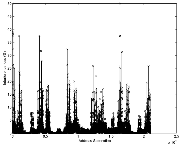 | Figure 3. Interference in a two-master cluster: CLKs are synchronized and maximum value of Diff =20,000 |
Experiment 2: This experiment is similar to Experiment 1 except that the CLKs of the two Masters are not synchronized. The resulting interference data are shown in Fig. 4. Even if the native clocks of the Masters are not synchronized, the interference rate is up to 5%. | Figure 4. Interference in a two-master cluster: CLKs have random values |
Experiment 3: This experiment has been designed by combining Experiment 1 and Experiment 2. In this experiment, we want to observe the combined interference seen by one piconet from specially chosen five other Masters. We randomly chose an address for Master 1 and then chose the addresses of the five other Masters such that their address difference with Master 1 are 1, 4, 16, 20, and 64. While performing experiments, the native clock of Master 1 was fixed at a certain value and the native clocks of the five interfering Masters were chosen such that their difference with that of Master 1 varies from 0 to 1000. Finally, the average interference rate was calculated by repeating this experiment ten times. The resulting interference is shown in Fig. 5. In Fig. 6, we show the initial part of Fig. 5. For small clock differences, the interference seen by Master 1 due to the five other Masters isas high as 85%. However, as the clock difference increases, the interference seen by Master 1 decreases but still remainsat a relatively high rate of 10-20% compared to the expected rate of about 5% [5]. | Figure 5. Interference in a six-master cluster |
 | Figure 6. Interference in a six-master cluster (detailed) |
Experiment 4: In this experiment, we chose a pair of Masters with consecutive addresses and vary their clock difference from 0 to 5000 while performing experiments. We repeated this experiment ten times, calculated the average interference rate, and plotted the resulting data in Fig. 7. It was observed that in a cluster of just two masters the interference is 5-10% even with their clocks was not synchronized. Had the two Masters have random addresses; the expected interference is just around 1.26%. | Figure 7. Interference in a two-Master cluster with consecutive addresses |
4. Conclusions
Using an actual implementation of the hop selection kernel of Bluetooth, we simulated packet interference to observe if certain device addresses are more prone to mutual interference under certain clock conditions. We observed that if the clocks of two Masters are synchronized, then the two Masters produce mutual co-channel interference up to 50% depending on their address differences. In the case where their clocks are randomly chosen, the interference is still up to 5%, whereas the expected rate is just 1.26%. In a specially chosen cluster of six Masters, interference seen by one Master due to the others can be as high as 85% under clock synchronization and upto 10% when they are asynchronous, where the expected interference is just about 5%. If two Masters have consecutive addresses, then their mutual interference is up to 5-10% even when they do not have the same value for their clocks. This study reveals that packet interference in a certain cluster of Bluetooth Masters is actually determined by their device addresses and the asynchrony among their native clocks. Therefore, unless care is exercised in the selection of device addresses in a Bluetooth scatternet for personal area networking, the available data rate will be extremely low.
References
| [1] | The Bluetooth Special Interest Group, “Specification of the Bluetooth System Version 4.0,” http://www.bluetooth.org, June 2010. |
| [2] | C. Gomez et al., “Overview and Evaluation of Bluetooth Low Energy: An Emerging Low-Power Wireless Technology,” MDPI Sensors 2012, http://www.mdpi.com/ journal/ sensors, no. 12, pp. 1734- 11753, 2012. |
| [3] | G. Chakraborty et al., “Analysis of the Bluetooth Device Discovery Protocol,” Wireless Networks, vol. 16, no. 2, pp. 421–436, Feb. 2010. |
| [4] | A. El-Hoiydi, “Interference Between Bluetooth Networks– Upper Boundon the Packet Error Rate,” IEEE Communications Letters, vol. 5, no. 6, pp. 245–247, June 2001. |
| [5] | K. Naik et al., “Analysis of Packet Interference in a Cluster of Bluetooth Piconets Under Different Traffic Conditions,” IEEE Journal on Selected Areas in Communications, vol. 23, no. 6, pp. 1205–1218, June 2005. |
| [6] | S. Y. Shin et al., “Packet Error Rate Analysis of ZigBee Under WLAN and Bluetooth Interferences,” IEEE Transaction on Wireless Communications, vol. 6, no. 8, pp. 2825–2830, Aug. 2007. |
| [7] | C. Drula et al., “Adaptive Energy Conserving Algorithms for Neighbor Discovery in Opportunistic Bluetooth Networks,” IEEE Journal on Selected Areas in Communications, vol. 25, no. 1, pp. 96-107, Jan. 2007. |
 Abstract
 Reference
 Full-Text PDF
 Full-text HTML