-
Paper Information
- Next Paper
- Paper Submission
-
Journal Information
- About This Journal
- Editorial Board
- Current Issue
- Archive
- Author Guidelines
- Contact Us
Journal of Wireless Networking and Communications
p-ISSN: 2167-7328 e-ISSN: 2167-7336
2013; 3(3): 19-28
doi:10.5923/j.jwnc.20130303.01
User Datagram and Bundle Protocol for Distributed Small Satellite Topologies
 Abstract
 Reference
 Full-Text PDF
 Full-text HTML
Paul Muri1, Janise McNair1, Joe Antoon2, Ann Gordon-Ross2, Kathryn Cason3, Norman Fitz-Coy3
1Wireless and Mobile (WAM) Systems Lab, Department of Electrical and Computer Engineering, Gainesville, FL 32611, USA
2Center for High Performance Reconfigurable Computing (CHREC), Electrical and Computer Engineering, University of Florida
3Space Systems Group (SSG) Department of Mechanical and Aerospace Engineering University of Florida Gainesville, FL
Correspondence to: Paul Muri, Wireless and Mobile (WAM) Systems Lab, Department of Electrical and Computer Engineering, Gainesville, FL 32611, USA.
| Email: |  |
Copyright © 2012 Scientific & Academic Publishing. All Rights Reserved.
Many planned Earth observation satellite missions use distributed satellite systems in constellation or cluster orbits instead of one, large satellite with many instruments. This network of satellites and ground stations allows data to be efficiently downlinked. However, to create a networking protocol for constellations of small Earth observing satellites, several limitations need to be addressed, including distributed topology management, slow downlink data-rates, and single point-to-point communication. Since distributed satellite constellations exacerbate the severity of these limitations, a thorough analysis of a constellation's network performance is required to ensure that task objectives are achievable. In this paper, we compared low Earth orbit(LEO) Earth observing satellite constellations using delay tolerant networking protocols and the user datagram protocol (UDP). The constellations' inter-satellite links and downlinks were evaluated using network metrics such as access window time, drop-ratio, and throughput. We simulated these network metrics using the Network Simulator 3 (ns-3). Previous works have proposed satellite constellations for Earth observation, however, constellations of small satellites have not been analyzed for network metrics. Results show that a sun-synchronous constellation with a repeating ground track outperforms a flower constellation with respect to increased access time, reduced drop-ratio, and higher throughput. The simulations also determined the optimum media access control slot time and packet transmission intervals for long distance satellite links. Additionally, we were able to compare the throughput performance of UDP to abundle protocol by adding nodes with delay tolerant networking protocol implementations.
Keywords: Communication networks, Delaytolerant networking (DTN), Network topology, Satellite communication, Satellite constellations, Network simulations, User datagram protocol (UDP), Vehicular networks, Wireless mesh networks
Cite this paper: Paul Muri, Janise McNair, Joe Antoon, Ann Gordon-Ross, Kathryn Cason, Norman Fitz-Coy, User Datagram and Bundle Protocol for Distributed Small Satellite Topologies, Journal of Wireless Networking and Communications, Vol. 3 No. 3, 2013, pp. 19-28. doi: 10.5923/j.jwnc.20130303.01.
Article Outline
1. Introduction
- Smallsatellites are satellites based on a pico-satellite platform with a mass of less than one kilogram. Even though small satellites have grown in popularity, a size constraint of 10x10x10 cm[1] severely limits these satellites’ power and communication.With these limitations, small satellites have low transmission power due to a limited solar panel capacity of two watts and high latency due to the long propagation distance between satellites and ground stations, which can range up to 750 km for downlinking and 2,000 km for intersatellite linking. These satellites are exclusively launched in low Earth orbit (LEO)[2], which leaves a limited timewindow to link with ground stations. Depending on the orbital parameters and the location of the ground station, a single LEO satellite may only downlink two to three times per day for ten-minute periods.Thus, a communication protocol is needed to allow bursts of data to be downlinked efficiently when there is a line of sight connection with the ground station. To mitigate these limitations, researchers are developing constellations with several satellitescoordinating to perform a single task[3].A constellation’s task dictates the constellation’s specific design. In some cases, multiple candidate constellation types may be appropriate for the same task. Traditionally, to minimize deployment cost, constellation types were selected to minimize the number of satellites given the constellation’s coverage requirements. However, when designing constellations of multiple satellites that communicate over inter-satellite links, the constellation’s network performance (i.e., the quality of the inter-satellite links) becomes a criterion for constellation selection.Delay tolerant networking (DTN) protocols were used in several prior space missions, including the Deep Impact Network Experiment in 2005, the UK-DMC in 2008, the International Space Station in 2009, and the “Internet Router In Space” (IRIS) on the IntelSat-14 in 2011[2]. The Consultative Committee for Space Data Systems (CCSDS) has standardized the bundle protocol for further use on geosynchronous satellite missions, such as the Laser Communications Relay Demonstration.However, small satellite missions could also benefit greatly from DTN protocols because these satellites typically coordinate as constellations[2].In order to compare candidate constellation types for effective satellite mission design, the effects that the constellations’ typeshave on the inter-satellite link network performance must be evaluated. Simulation is commonly used to evaluate network performance, and satellite packages are available for OMNeT++, OPNET, QualNet, and the Network Simulator (ns)[4]. However, most satellite simulation packages are for large satellites with more powerful transmitters than the transmitters available on small satellites. Some research focused on evaluating network performance of specific protocols for satellite constellations using network simulators[5-6]. However, these studies have focused on evaluating protocol performance or optimizing a single satellite constellation rather than comparing candidate constellation types using network performance as a criterion.The rest of the paper is organized as follows. Section 2 provides background on Delay Tolerant Networking including User Datagram and Bundle Protocols and DTN simulation issues. In Section 3, we describe the constellations modeled in satellite tool kit, and the parameters used for the network simulation. Then, in Section 4, we detail the dropout ratio, throughput, and data rate results from simulation. Last, in Section 5, we draw conclusions regarding optimum slot time values for BP/UDP and discuss future work.
2. Background on Delay Tolerant Networking (DTN)
2.1. User Datagram and Bundle Protocol
- DTN is a suite of communication protocols that has been used to address challenging environmental conditions that create delay and intermittent connectivity. Examples of these challenging network environments include sensor networks for wildlife tracking(ZebraNet)[7], connectivity in remote and undeveloped regions (DakNet)[8], vehicular network infrastructures (SUVNet)[9], social proximity-based networks (Peoplenet)[10], underwater acoustic networks (NURC WHOI Micro-Modem)[11], and networking space missions (IRIS)[2].In 2002, the common goals of MANETs and sensor networks led the Internet Engineering Task Force (IETF) to form the DTN Research Group (DTNRG)[12]. The DTNRG works on protocol design, technical specifications, and develops code for the reference implementation, called DTN2. In 2007, the IETF published the request for comment (RFC) 5050, which defined a standard protocol for DTN known as the Bundle Protocol (BP)[13]. Bundles defined in BP contain data that helps a network application move chunks of data larger than packets, known as bundles. BP operates with non-IP (internet protocol) and IP transport layers, known as convergence layers, in a store and forward method between nodes. The architecture of BP works as an overlay network and uses Endpoint Identifiers (EID) as a naming scheme to identify the final destination nodes.For DTN nodes, the bundle layer is immediately below the application layer. This stack position allows BP to masklayers from the application, as depictedin Figure 1.
 | Figure 1. A diagram of the network stack for DTN and TCP/IP |
2.2. Evaluating BP/UDP for Small Satellites
- Typically, small satellites have operated over the AX.25 link layer protocol at point-to-point links[2]. Related projects use Digital Smart Technologies for Amateur Radio (DSTAR) on satellites such as OUFTI-1[15]. For small satellites, DTN can run on top of AX.25, and a DTN convergence layer adapter has been implemented for the link layer protocol AX.25[16]. However, DSTAR and AX.25 protocols are exclusively point-to-point and downlink on VHF and UHF spectrums. These spectrums do not contain the bandwidth needed for data rates above 38.4 kilobits per second[15].Thus, an evaluation of running DTN protocols over UDP for LEO constellations and cluster topologies is needed. By linking Linux containers (LXCs)[17] through virtual local area networks (LANs), we can determine the data rates and access times for LEO satellites to form intersatellite links and downlink with ground stations. With our method, gateways and routers are authenticated as DTN agents. Forwarding nodes also authenticate the sender data such that traffic can be stopped at the earliest point in the route. To deal with the high frequency of disruptions, bundles can be stored in forwarding nodes for a long period of time(e.g., minutes or days, as needed). In this way, retransmission does not have to occur end-to-end. Store options are configured at the bundle layer but can be set by the application.
2.3. Past DTN Network Simulations
- Network simulators, such as DTNSim2 and the Opportunistic Network Environment (ONE), have been used in previous studies, however, DTNSim2 is no longer supported and ONE development was discontinued in 2011[18]. Often, these simulation platforms require high computing resources.Additionally, for DTN simulators to be most effective for space inter-networking, the simulators must be highly realistic. Many DTN simulators do not currently implement realistic channel models or the networking stack. There is also an issue of cross-simulator comparability. Researchers often create their own simulators to test algorithms, making it difficult to compare new algorithms with existing algorithms unless the new protocol is implemented on a variety of simulators. Many DTN implementations have been written for various platforms. For our experiments, we used DTN2 for a BP reference implementation.
3. Modeling Network Topologies for LEO Constellations
3.1. Types of Satellite Constellations
- Satellite constellations can be used to cover large areas of the Earth’s surface. Examples include GPS (global positioning system) for navigation, RapidEye for Earth imaging, and Iridium for communications. A constellation’s task dictates the constellation’s specific design. In some cases, multiple candidate constellation types may be appropriate for the same task. Sun-synchronous orbits have desirable features for remote sensing, Earth observation, and weather, since these orbits have near constant illumination angles. An equatorial repeating-ground track orbit allows for approaching the ground station at an identical angle, and encountering the ground station more frequently than the sun-synchronous orbit, at up to twelve times per day[19]. A repeating ground-track satellite could act as a sink to relay the sun-synchronous satellite’s observation data. However, all satellites would need propulsion capabilities to be placed in this constellation.With no propulsion required, satellite clusters allow for faster build times, simpler designs, more redundancy, higher resolutions, and multiple angles and times for observation. An example of this type of cluster is the QB50 program[20], which has called for a cluster of 50 small satellites for a magnetosphere study. These satellites do not transmit through inter-satellite links for the QB50 mission. However, we envision that an inter-satellite networking capability in such a mission could take advantage of the cluster topology for distributed processing and higher data relay to a ground station.
3.2. Network Management in the Satellite Toolkit (STK)
- To evaluate the network performance of arbitrary satellite constellations, we used Network Simulator 3 (ns-3), an established network simulator[21]. To include DTN implementations on ns-3 nodes, our experiment used standardized, open source, physical and link layer simulation modules, and leftthe higher layers as standard DTN implementations on virtualnodes.We mitigated the effects of limited LEO satellite access to ground stations by employing the data mule methodology proposed by[22]. The data mule methodology consists of usinga set of source satellites to collect data, and a set of sink satellites to transport the collected data to a ground station.In order to maintain relevancy between the two candidate constellations, we designed each candidate constellation to contain ninesource satellites and six sink satellites.The sink satellites are larger, more powerful satellites with more access time to the ground stations than the source satellites, but less access time to the target areas than the source satellites.
3.2.1. Sun-synchronous Repeating-ground Track (SSRGT)
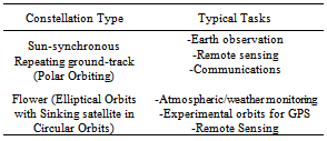
- Sun-synchronous repeating-ground track (SSRGT) orbits have desirable features for remote sensing and Earth observation applications since these orbits have near constant illumination angles and approach targets with identical viewing angles up to twelve times per day[19]. These characteristics are amenable to Earth observation missions in both the visible and infrared spectrum. Satellite systems, such as the LANDSAT program[23], and imaging and remote sensing satellites and constellations, such as Spot satellites[24] and RapidEye[25], leverage the SSRGT orbit. The Flower constellation is an elliptical orbit proposed for atmospheric, weather monitoring, experimental orbital for GPS and remote sensing[26]. Table 1 shows the typical applications for both the SSRGT and Flower constellations.
|
|
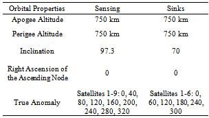
 | Figure 2. A diagram of our SSRGT constellation shows the right-most lines near the North Pole crossing to the left-most near the South Pole represent the six sinks’ orbiting path. The left-most line near the North Pole crossing to the right most near the South Pole represents the nine sensing satellites’ orbiting path, generated in STK, based on Table 2 data from [27] |
|
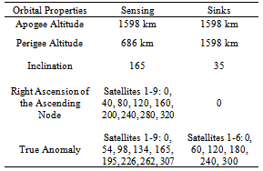
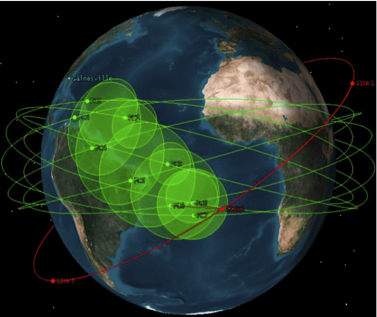 | Figure 3. A diagram of our flower constellation shows the bottom-most line on the left crossing to the top-most on right as the six sink satellites’ orbiting path. The horizontal lines near the Equator are the nine sensing satellites’ orbiting paths, generated in STK, based on Table 3 data from [27] |
3.2.2. Flower Constellation
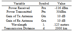
- The flower constellation is a particular type of repeating ground-track orbit with an axis of symmetry that coincides with the spin axis of the Earth. Flower constellations are well suited for Earth observation because each source satellite in a flower constellation has the same orbit shape and all the satellite node lines are displaced equally along the equatorial plane[27].In order to maximize access time to the target, all nine flower constellation source satellites are in an elliptical, near-equatorial LEO. In order to accommodate the data mule methodology and maximize sink satellite time to our ground station, we distributed the six flower constellation sink satellites in a traditional circular 1598 km orbit with a 35◦ inclination. Table 2 shows a comparison of the orbital parameters for the flower constellation design.The topologies for the two constellations of LEO satellite missions were designed using thesatellite toolkit (STK)[28]. The constellations were evaluated for network performance using ns-3. In STK, both constellations were simulated over a same three-monthperiod. The simulation time resolution was one minute. Access time between the sensing satellites and the sink satellites determined the transmission window. The access time is the time, in seconds, for two satellites to communicate with one another, given a range limit in kilometers.A previous study tested several potential directional satellite antennas for 2.45 GHz[29]. From this study, a 10db transmission (Tx) and receiver (Rx) gain was assumed.The range limit threshold for a 12.5 cm wavelengthis a maximum of 2,000 km, solved from the Friis Pathloss Equation (1).
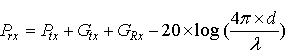 | (1) |
|
 | Figure 4. A chart of the SSRGT constellation if launched January 12th. The bars indicate transmission windows when the nine sensing satellites can forward data to the sink satellites, generated in STK, based on Tables 2 and 3 data from [27] |
 | Figure 5. The node access time versus the communication link range |
3.3. Mobility Model
- Flood routing was used for our simulations. To determine the network layer’s connections,we used a mobility model from a previous study, SatLauncher, which is a Java-based orbit propagation and visualization software that models a satellite’s mobility upon launch of a cluster[20]. The orbital parameters of each satellite were calculated given altitude, radius, rotation rates, mass, and launcher velocity. The velocity in the x-axis and z-axis was calculated by Equation (2).
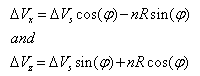 | (2) |
3.4. Doppler Shift
- To address the Doppler shift, we integrated Jakes propagation loss modelinto the network simulation. The model’s parameter for Doppler frequency shift, fd[Hz] can be calculated from the velocity V[m/s], transmission frequency f[Hz], and light speed c[m/s] in Equation (3). In[31], a Doppler shift of 50 kHz is experienced in circular LEO satellite formations,thus this orbit is within the 802.11 mobility specification with a maximum frequency variation of nominally ±60 kHz[31].
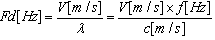 | (3) |
3.5. Network Performance from the Network Simulator 3 (ns-3)
- The ns-3 package contains multiple models for simulating satellite constellations and the obvious model choice for our simulations is the satellite model, which can simulate well-known constellations such as Iridium[2]. However, since this satellite model only supports circular orbits with un-slotted ALOHA-net as the link layer protocol, we used the mobile node model with each satellite represented as a node.The mobile node model is robust and supports a wide range of protocols. However, since this model is most appropriate for terrestrial wireless networks, we modified the mobile node model to simulate our constellations. Creating a mobile node simulation typically consists of plotting the nodes’ movements as tool command language (Tcl) scripts, called scenarios. However, since three-dimensional (3D) positioning is not supported, we could not simply write a script to translate the 3D satellite movements into a scenario.In order to integrate 3D movements, we modified the positioning system. Unlike the other simulation models, the mobile node model is not easily modifiable and inhibits direct replacement of the positioning system. To overcome this restriction, we wrote new modules to replace the existing modules interfaced with the positioning system. The new modules used an external database of satellite positions to provide node position information.To use the STK constellation data in our new modules, we used STK to export our SSRGT and flower constellations as comma separated value (CSV) files. The CSV files contained a position for each satellite at every minute. We wrote a Python script to translate the satellites’ positions into a structured database and we wrote a C++ library to load, cache, and linearly interpolate the satellites’ positions at times between the recorded minute positions. Using our C++ library, we replaced any module that used node positions with a version that used STK-exported data.A node’s position has two primary uses in the mobile node model. First, the node’s position is used to calculate the receive power of the transmissions that a node receives. Each node contains a wireless PHY module that activates when any node in range transmits a packet. The wireless PHY module contains a propagation module that calculates the packet’s receive power.The propagation module uses the transmitting and receiving nodes’ positions to calculate the transmission’s propagation distance. For simplicity and due to the direct line-of-sight transmissions in LEO, we used the FreeSpace propagation module, which is based on the Friis transmission Equation (1). The FreeSpace module uses the distance between the transmitting and receiving nodes to calculate each packet’s receive power.In order to interface with our external satellite position databases, we added a new module, FreeSpaceSTK. Modules can define Tcl commands, which Tcl scripts can call to perform module-specific actions. We wrote a command handler for the FreeSpaceSTK module for a new command that logically links a node to a corresponding satellite position database. The FreeSpaceSTK receive power calculation uses the satellites’ position databases instead of the mobile node positions to calculate node distance. FreeSpaceSTK doesnot, however, calculate the radio propagation delay. Figure 6 shows the structure of the modules that use the nodes’ positions.
 | Figure 6. The ns-3 wireless transmission simulation model |
3.6. Bundle Protocol (BP) Experiment Setup
- To simulate BP, and compare with UDP, DTN2implementations ran on virtual machines. Virtual machines create a native environment for the DTN software and provide virtual hardware on which operating systems can be installed on a host system and configured according to the DTN software requirements with minimal impact to the underlying host. Of the various virtual platforms available, Oracle’s VirtualBox [32] was used because, with available open source editions, modification is feasible. However, VMWare Player or VMWare Server[33] could also be used.For this experiment, ns-3 modules simulated physical DTNs up to the data link layer as WiFi-type given topology and mobility patterns, ranges, and data rates.For the higher layers, connections to virtual machines were bridged using IEEE 802.3 in the host system.The entire experiment ran on one host machine. The components includedns-3 and the virtual machines with the DTN2 network software stack and DTN applications, subject to testing and integration, run on top.The experimentmodeled communication channelproperties, such as delay, transmission rate, error, and packet loss distribution, with detailed scheduling. The simulation allowed configuration for mobility patterns of wireless nodes, networking device properties at the physical and link layer, logging, and packet tracing. If required, new models could be constructed and used in the simulations.As a main network simulation and server Linux platform, Fedora Linux 64-bit distribution was selected as the host machine’s operating system. We used the Ubuntu Linux distributionfor the virtual machines due to the availability of the DTN2 reference implementation. The host hardware could be any standard personal computer or laptop compatible with the operating system with at least 8 GB of RAM and disk space to allow for many virtual machines. Different hardware platforms of interest, such as Broadcom or ARM,could be integrated by physically connecting these platforms into the system through an access point. The ns-3 comes with a number of channel and device models, including WiFi and WiMax. The DTN2 systems and application software that run on the virtual nodes come from the DTNRG.The Wifi network models are built into the ns-3 source code shown in Figure 7. Wi-Fi is considered the common type of link for the DTN tested. Bundles were onemegabytein size.
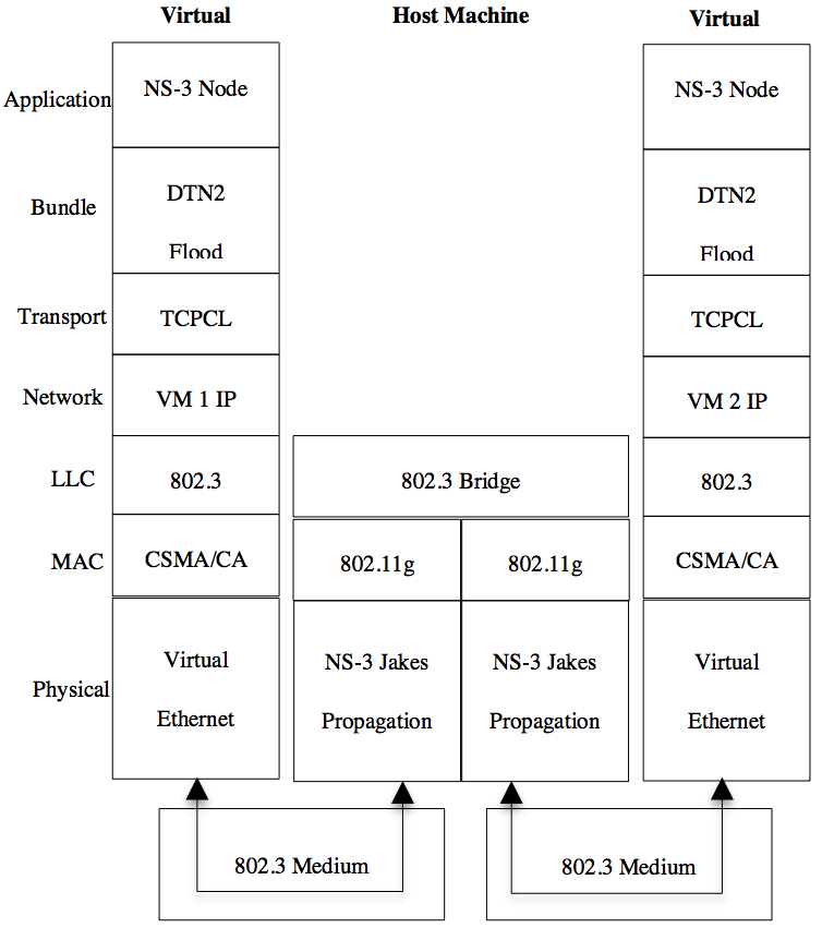 | Figure 7. A diagram of the network stack for transmitting bundles between virtual machines |
4. Results
- We applied the modifications described in Section 3 to the ns-3installations running on Ubuntu Linux. To run our experimental simulations, we created two Tcl scripts: one script defined the nodes using our flower constellation positions and the other script defined the nodes using our SSRGT constellation positions.The Tcl scripts specified the protocol for each satellite node’s network layers. We used the simulation modules for each node’s MAC layer since 802.11b-1999 has acceptable long-range performance and a wide range of available commercial-off-the-shelf hardware. For each node’s PHY layer, we used the standard wireless PHY module with the propagation configured to use our FreeSpaceSTK module.We configured the FreeSpaceSTK module in one of the Tcl scripts to use the satellite position database for the flower constellation and the other Tcl script to use the satellite position database for the SSRGT constellation. To simulate the communication channel, we used our WirelessChannelSTK module. The nodes defined by the Tcl scripts behaved like satellites in a constellation and could support traffic from most agents.We wrote a Tcl scenario to generate sample traffic for the simulation. In the Tcl scenario, each non-sink node generated constant bit rate (CBR) traffic over a UDP agent to each of the six sink nodes. To prevent the source nodes that were out of range of any sink satellites from transmitting, we assumed that satellites could detect the presence of sink satellites within 2000 km. Source nodes only transmitted data when they were within 2000 km of a sink node or the ground station in Gainesville, Florida.
4.1. Dropout Ratio Versus MAC Slot Times
- Since the performance of the MAC layer is significantly affected by the large propagation delay between communicating satellites in LEO, we first conducted simulations to find optimal 802.11b-1999 MAC module parameters for our scenarios. The standard 802.11b-1999 slot time, the time allocated for a round-trip packet transmission, and acknowledgment is 20 μs, and the short inter-frame spacings (SIFS) are 10 μs[21]. However, for satellites that are 2500 km apart, radio signals take over 8ms to propagate at the speed of light. Our 802.11b-1999 timing parameters were built around Equation (4) from studies by Vladimirova[34] that extended the slot time to 75μs for nodes at 15km apart and later used a slot time of 355μs for nodes 100km apart.
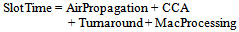 | (4) |
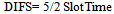 | (5) |
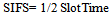 | (6) |
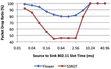 | Figure 8. Packet drop ratio versus MAC slot time |
 | Figure 9. A comparison of the ground to sink satellite drop ratio versus MAC slot time |
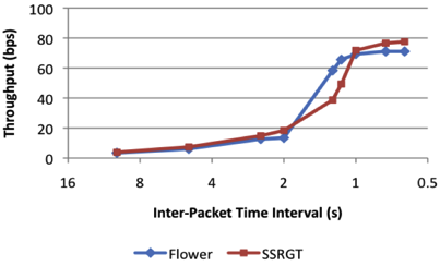
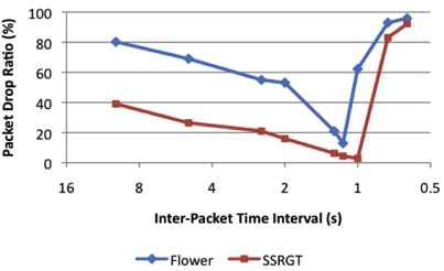
4.2. Throughput Versus Source Traffic Density
- We tested the traffic capacity of the flower and SSRGT constellations’ networks by simulating the network throughput while increasing the source traffic density (the rate at which the source nodes send packets). Figure 10 shows the network throughput for both the flower and SSRGT constellations between 10bps and 80bps.Figure 11 shows the packet drop-ratio for the SSRGT and flower constellations as a function of source traffic density. The flower constellation maintained a similar throughput as the SSRGT constellation even though the SSRGT constellation dropped fewer packets than the flower constellation. The higher packet drop-ratio for the flower constellation as compared to the SSRGT constellation, combined with the constellations’ similar throughputs, suggests that the flowerconstellation has more opportunities than the SSRGT constellation to transmit data from long distances. Both constellations suffered very low throughputs, which is expected due to the weak transmitters and long distances involved in the simulation.
 | Figure 10. Throughput versus source traffic density |
 | Figure 11. Comparison of packet drop ration versus source traffic density |
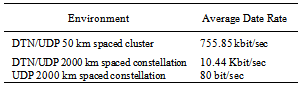
4.3. Data Rates Running BPOver UDP
- The default DTN configuration used a UDP convergence mechanism, but to the simulation platform, the traffic generated is identical to any IP traffic. Tests were performed on intermittently connected Wi-Fi examples with virtual nodes and Linux containers[17]. Tests of simple DTN applications show that the platform effectively models network connectivity. The results show that the platform is capable of modeling various connectivity patterns in a manner transparent to IP packets.When compared with a UDP/IP, the DTN metrics show higher data-rate, lower bundle-drop ratio, less overhead, and longer transmission windows for the given mobility models. For a cluster of DTN-enabled wireless nodes with an initial spacing of 2,000 km, the average data rate is 10.44 Kbit/sec. In comparison,the UDP/IP network of nodes at distances of 2,000 km had a data rate of 0.08 Kbit/sec.
|
5. Conclusions and Future Work
- In this paper, we developed a method for comparing the network performance for constellations designed using the satellite toolkit (STK) based on sink time, drop-ratio, and throughput. Using this method, we designed and compared the network performance of two novel small satellite constellations: a flower constellation and a sun-synchronous repeating ground track (SSRGT) constellation. In order to compare the constellations’ network performance, we modified the Network Simulator 3’s (ns-3’s) mobile node model to simulate complex satellite constellations. Results revealed that as the satellites opportunistically communicated during a week in simulation time, the satellites in the SSRGT constellation dropped fewer packets than the satellites in the flower constellation. During a period of 500 ms to 1 second, the SSRGT satellites showed a higher throughput. Further, modifying ns-3 with a delay tolerant bundle protocol (BP) increased data rates substantially. Our simulation files and related scripts described in the article are available upon request.Future work includes benchmarking delay tolerant networking (DTN) protocols on embedded hardware viable for small satellites. Future tests can compare the performance and determine likely limiting factors for hardware platforms.In addition,we will incorporate multiple ground stations[35] and compare the network performance and coverage of satellite constellations to satellite cluster formations in which several satellite nodes fly in a single orbit, with one satellite node in the cluster serving as a sink.
ACKNOWLEDGEMENTS
- This work was supported in part by the National Science Foundation (ECCS-0901706). Any opinions, findings, and conclusions or recommendations expressed in this material are those of the author(s) and do not necessarily reflect the views of the National Science Foundation.We would also like to thank NASA Office of Chief Technologist’s Space Technology Research Fellowship (NSTRF) grant #NNX11AM73H for supporting this work.